
kogan FS7MDSTBBMA FORTIS 3 700C Bafang Mid-Drive Electric Bike User Guide
SAFETY & WARNINGS
Electric Assisted Bike Regulations
The EN 15194 EU standard or EPAC (Electric Power Assisted Cycle) conforms to the followingcharacteristics for electric power assisted bikes:
- Motor assistance only starts when the cyclist pedals.
- The assistance cuts out as soon as the cyclist stops pedalling.
- The assistance cuts out as soon as the speed exceeds 25km/h.
Adherence to this standard enables the use of the electric bikes in the same conditions as any other bicycle, particularly on bicycle paths and bicycle-specific lanes.
Recommendation before First Ride
- Before first use, double-check the function of all the parts of your electric bike. If youhave any doubts or if you detect a problem, contact Kogan.com for further support assistance.
- If you lend your bicycle to a third party, give them this user guide with the bicycle and ensure that they read it before the first ride.
- Respect local, state and national road traffic regulations.
- For your safety, it is highly recommended that you wear a certified helmet. Ensure you are always following local helmet laws while operating the bicycle.
- When used during heavy rain, snow, in slippery conditions or in the case of low visibility, be careful and adjust your speed.
- At night, ensure the bicycle headlights are activated while operating.
- Trying to repair anything that involves removing technical or electrical componentsis strongly advised against. If maintenance or repair is necessary, contact Kogan.com for support assistance.
- The manufacturer declines any responsibility due to overloading or items that are not correctly attached to the baggage rack.
- Using high pressured water jets to clean the bike is strongly advised against.
- Check the battery level before each use. Ensure the battery is fully charged prior to first use.
- In order to extend battery performance and lifespan, do not commence operation when the battery is only half-charged.
- The battery life will vary depending on where you ride it (inclines will reduce power rapidly) and how you ride (assistance mode chosen). The greater the assistance used, the more you’ll use the battery and the shorter it will last. This bike is fitted with gears; remember to use them accordingly relative to riding conditions in order to extend battery life. The amount of weight carried will also have an impact on battery lifespan. Extreme low temperatures can also impact battery lifespan.
- It is recommended that you charge the battery at least every 2 months when the bike is not used; during winter, for example.
- Store the battery in a dry place after having completely recharged it. Avoid extreme temperatures (both low and high) as they can damage the battery. Optimal operating range: -10°C to 35°C.
Cleaning and Maintenance
- Use a damp cloth with neutral detergent to clean the bike frame. Do not use any detergents or cleaning liquids liable to deteriorate the frame or components.
- Use a dedicated bicycle cleaner or hot soapy water to clean your bike and its components, such as wheels, hubs, rims, brakes and pedals. Rinse well with clean water before use.
- Do not use high pressure water jets to clean your bike, especially on the electrical components (such as the battery), as this may result in short circuiting or system malfunctions.
- All the components and parts of your bicycle are subject to normal wear and fatigue.
- Keep a close eye on any change in the shape or colour of a component or traces of oxidation (rust) on your bicycle. If this occurs, do not use the product until the component has been replaced.
Warning
- Do not ride after consuming alcohol or drugs (prescribed or not), or while under the affects of medication which might make you drowsy.
- Do not ride while you feel unwell, nor after consuming alcohol or drugs. This product has the potential to endanger yourself and others if not operated responsibly.
- Pedal-assisted bicycles are not designed for 2 or more people. Do not ride carry passengers as these bicycles are not designed to carry the additional load of a second rider.
- Do not put batteries in normal waste bins. Dispose of used batteries in a certified recycling facility.
- Do not over-lubricate; if oil contacts the wheel rim, brake pads or brake disks, this will result in loss of braking performance and an increase in stopping distances. This could potentially cause loss of control, accidents, and injury.
Transport
It is highly recommended that you do not overload your pedal-assisted bicycle, as this may damage the electrical components or cause malfunctions, such as overheating of the battery or the motor. Do not store the battery in excessively hot or cold places.
- Maximum transport weight on the bicycle must not exceed 75kg.
- Regularly check battery brackets and mountings.
- Always wear a helmet when riding your pedal-assisted bicycle.
- If a rack is not already fitted to your bicycle, please do not attempt to fit one yourself.
- Do not carry anything on the rack that might hide lights or reflectors.
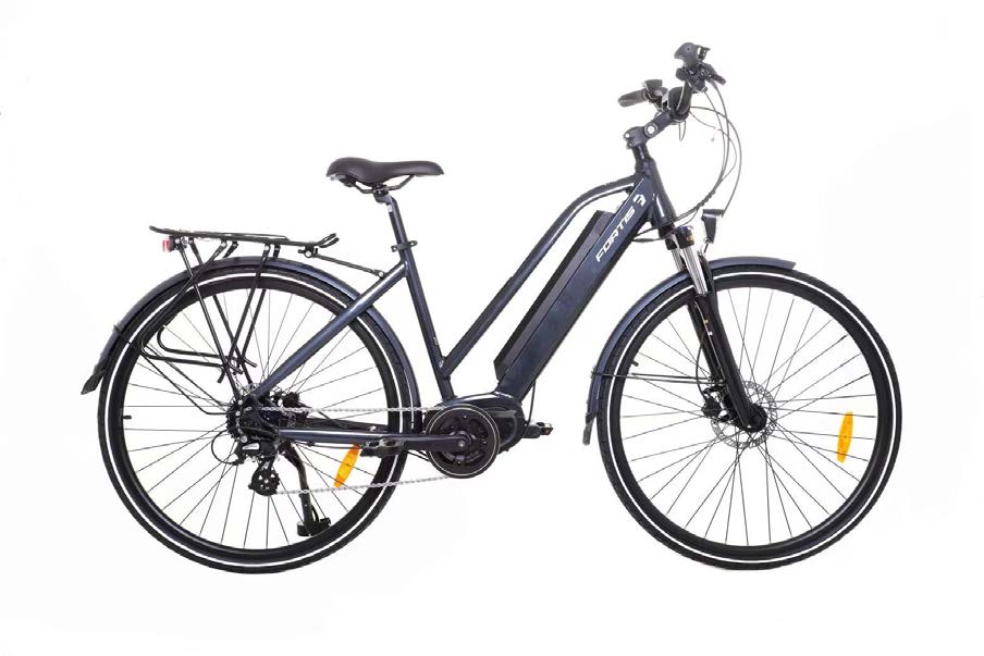
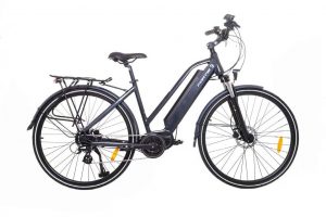
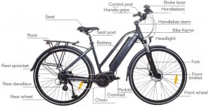
OVERVIEW
Basic overview
ASSEMBLY
Stem Assembly
Stem fitted in the head tube with an expanding bolt (Figure 1). Insert the stem into the head tube, respecting the minimum insertion limit as indicated on the stem and tighten the expanding bolt to 18Nm.
Before tightening the stem, make sure that it is in-line with the front wheel.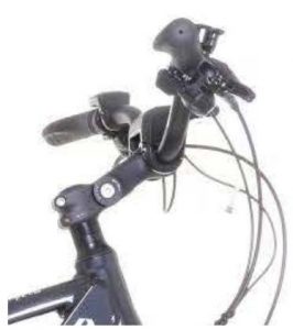 Figure 1
WARNING: To prevent steering system damage and possible loss of control, the stem must be inserted enough so that the minimum insertion marks are completely covered.
Handlebar AssemblyPosition the handlebar inside the stem (Figure 2). Respecting assembly indications on thehandlebar, tighten screw to 18Nm. Before completely tightening, check that the handlebar,the brake levers and shifter are correctly positioned.
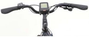
Figure 2
Wheel Mounting
Insert the maximum length of the skewer into the wheel hub, tighten locknut and tighten thewhole system with the quick release lever (Figure 3). Make sure that the wheel is correctlyfitted.
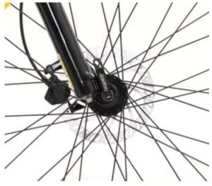
Figure 3
Brake AdjustmentAfter installing the front wheel, re-connect the front brake by squeezing the arms together and sliding the cable guide back into the carrier. The wheel should not rub on the brake pads. Next, squeeze the brake lever and take note of the brake pads contacting the side of the wheel. The pads should contact the rim on both sides at the same time. Finally, hold the brake lever firm and try to move the bike forward. The brake should hold well enough to keep the wheel from moving. Repeat these steps for the rear wheel.
Seat Assembly
Insert the seat stem into the frame (Figure 4), you can use grease to help assembly. Insert atleast to the minimal indication on the seat stem using rotary movements. Pull the quickreleaselever free and insert the seat-post to the minimal insertion marker indicated on the seat-post. Tighten the quick-release clamp and then fold the lever to closed position. Minimal torque specifications are 19.5Nm.
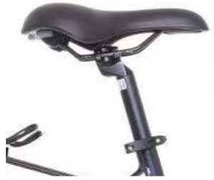
Figure 4
BEFORE FIRST USE
Recommendations and Component Control before UseBefore using your bicycle for the first time, you must check that all adjustments have been correctly made.
- Check that the front and rear brakes work, check brake pads for wear.
- Check the cables and sheaths and that the hydraulic system functions correctly.
Wheels and Tires
- Check tires are inflated to the pressure indicated (either in Bar or Psi) on the tire sidewall.
- Check that the tires are in good condition and are free from cuts or bulges.
- Check the state of wheel rims and ensure that spokes are correctly tightened.
- Check that the wheels are correctly fitted to the bicycle, either by a quick-release system or nuts.
WARNING: If a wheel rim or spokes are damaged, immediately replace the wheel.
Steering
- Check that the handlebar and stem are correctly tightened and that they are in line with the wheel and the fork.
- Check that the steering clamp is correctly tightened and adjusted in the right direction.
Frame and Fork
- Check that the frame shows no signs of fatigue or damage and that the fork works correctly.
Chain
- Make sure that the chain is at the correct tension.
- Make sure that it is clean, rust free and properly oiled. Use adapted lubrication for use in extreme weather conditions.
Seat and Seat-post
Make sure that seat and seat-post are correctly tightened and positioned.
Bearings
Check that all bearings are properly adjusted and lubricate if needed. Make sure that they are not too loose or that they have seized up. Check steering bearings, wheel bearings, pedal bearings and bottom bracket bearings.
Crank set and Pedals
Make sure that the pedals are correctly tightened and that the teeth of the crank set do not show any unusual wear.
Accessories
- Check front and rear lights; also check that horn/bell work.
- Make sure that the reflectors are not hidden.
- Check that the battery is correctly fitted and secured.
- Make sure that the rider wears a helmet.
Torque Specifications
- The handlebar is fitted to a stem. The height of some stems can be adjusted. If you must dismantle the handlebar or turn it to transport the bicycle, please make sure that you correctly reassemble and centre the handlebars; check the position by placing your hands on the grips to find the best position. Make sure all bolts are correctly tightened. Once handlebar and stem are assembled, make sure that the brake and derailleur sheaths are free. Recommended torque specification: 13- 14Nm. Recommended torque specification for the rear rack is 16Nm.
- You can adjust the angle of the stem by adjusting the bolt located under the stem using an Allen key. Once you have found the desired angle, tighten the stem to the headset. Recommended torque specifications are 18-20Nm.
- If you remove nut fitted wheels, make sure that when you replace them you respect a minimal recommended torque specification of 30Nm for the rear wheel and 25Nm for the front wheel.
OPERATION
1. Battery
1.1. Use the Battery Properly
- The battery can always be charged at any time no matter how much power is left. However, in the following cases, you should have the battery fully charged. Make sure to use the specified charger to charge the battery.
- The battery is usually not fully charged for the convenience of transport. Make sure the battery is fully charged before using the battery.
- If the battery is not intended for use in a long time, make sure the e-bike battery is charged before storage and is afterwards charged at least once every six months. Do not leave the battery completely discharged.
- Once you have begun to use the battery, please have it charged at least once every two weeks.
Note:If the battery is completely discharged, charge it as soon as possible. If you do not charge the battery, it will be damaged.
1.2. Charge the Battery
- When using the battery for the first time, check whether the battery has not run low due to transportation or storage.
- When the battery is not intended for use in a long time, charge the battery regularly to avoid excessive battery discharge.
- Please charge the battery as soon as possible before it runs out; over-discharge can cause permanent damage to the battery.
- No matter how much power is left, the battery can be charged at any time. However, the specified charger must be used to avoid overcharge of the battery.
- To maintain the proper use of the battery, do not subject the battery to heavy shocks or a heat source or disfeature the battery or short circuit its terminals.
2. Display
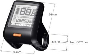
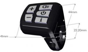
2.1 Appearance and Dimensions
The shell is made of PC (poly carbonate). The liquid crystal interface is made of hard hardness acrylic.
2.2 Function Overview and Key Definitions
Function Overview
- The display adopts a two-way serial communication protocol. The external five-key keypad enables users to operate the display conveniently.
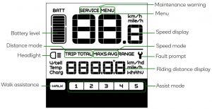
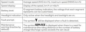
- Speed display: displaying the real-time SPEED, the max speed MAXS and the average speed AVG.
- Km or mile: the user can set the unit of distance as km or mile according to personal habit.
- Intelligent battery level indication: with an optimisation algorithm, a stable display of the battery level is ensured and the problem of fluctuant battery level indication common with an average display is avoided.
- Automatic light-sensitive headlight/taillight: as the outside light changes, the headlight and taillight will be automatically turned on/ off.
- Backlight brightness: there are 5 levels of brightness for the display backlight, of which Level 1 indicates the darkest backlight while Level 5 indicates the brightest backlight.
- The display adopts a two-way serial communication protocol. The external five-key keypad enables users to operate the display conveniently.
- Speed display: displaying the real-time SPEED, the max speed MAXS and the average speed AVG.
- Km or mile: the user can set the unit of distance as km or mile according to personal habit.
- Intelligent battery level indication: with an optimisation algorithm, a stable display of the battery level is ensured and the problem of fluctuant battery level indication common with an average display is avoided.
- Automatic light-sensitive headlight/taillight: as the outside light changes, the headlight and taillight will be automatically turned on/ off.
- Backlight brightness: there are 5 levels of brightness for the display backlight, of which Level 1 indicates the darkest backlight while Level 5 indicates the brightest backlight.
Items to be Shown on the Display:
Button overview
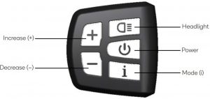
3. Normal Operation
3.1. Turning on
- Turn on the power. Press and hold the Power button for 2 seconds to power on the display.
- To turn the display off, press and hold the Power button for another 2 seconds
- If the bike is left unused and the display is left un-operated for 5 minutes (the time can be adjusted by the user), the display will be automatically turned off.
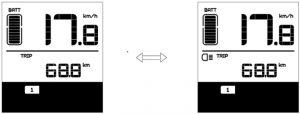
3.2. Assist Mode Selection
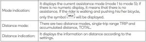
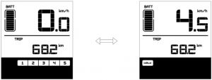
In the manual gearshift mode, press the Increase “+” or Decrease “–” buttons to switch the assist mode to change the motor assist power. The lowest mode is Mode 1 and the highest mode is Mode 5. When the display is on, the default mode is Mode 1. It indicates no power assist when there is no numeric mode display.
Assist Mode Selection Interface
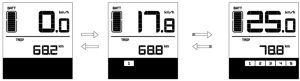
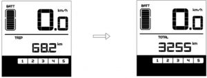
3.3. Distance Mode and Speed Mode Switch
Press the Mode (i) button to switch distance/speed display information, giving a display of single-trip distance (TRIP km), accumulated distance (TOTAL km), maximum riding speed (MAXS km/h), average riding speed (AVG km/h), Range and OC sequentially.
Mode Switch Interface
Note:Range and OC settings are displayed in the menu but are non-functioning for this model. This does not affect the bike’s operation.
3.4. Headlight/ Backlight Switch
- After pressing and holding the Headlight button for 2 seconds, both the backlight of the display and the headlight (needing the support of the controller) will be turned on.
- Hold and press the Headlight button again for 2 seconds to power off the headlight and the display backlight.
Note: If the display is turned on in a dark environment, the backlight/ headlight will be automatically turned on. But if the backlight/ headlight is then manually turned off, they have to be manually turned on afterwards.
- This model features front and rear battery lights. You can turn the lights on/off with the button on the lights.
3.5. Walk Assistance Mode
After pressing and holding the Decrease (–) button for 2 seconds, the electric bicycle enters the state of walk assistance and the symbol WALK is displayed in the field of assistance mode.
Once the Decrease (–) button is released, the electric bicycle will exit the mode of walk assistance.
Walk Assistance Mode Switch Interface
3.6. Battery Level Indication
When the battery voltage is normal, the battery is indicated by a certain number of segments with the border lighted according to the actual quantity of electricity. It the battery is under-voltage, all of the 10 segments will black out with the border blinking, indicating that the battery needs to be charged immediately.
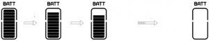
Battery Level Indication
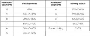
Table for Battery Level Check:
4. Parameter Setting
Setting Preparation
When the display is active, pressing the Mode (i) button twice (the interval between the two pressing actions should be shorter than 0.3 seconds), the system will enter the MENU parameter setting state, in which the display parameters can be set. Press the Mode (i) button twice again to exit the parameter setting state.
Enter the Parameter Setting Interface
In the parameter setting state, when the parameter to be set begins to flash, press the Increase (+) or Decrease (–) buttons to adjust the parameter value. Press the Mode (i) button to switch among the to-be-set parameters. Press the Mode (i) button twice (the interval between the two pressing actions should be shorter than 0.3 seconds) to exit the parameter setting state.
In the parameter setting state, if no operation is performed to the display for 10 seconds, the display will return to the normal riding state.
Data Reset:
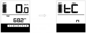
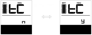
After pressing the Mode (i) button (the interval between the two pressing actions should be shorter than 0.3 seconds), the display enters the MENU state. In this state, the speed field displays ‘tC’ and then also displays ‘y’ after pressing the Increase (+) button.
At this moment, the temporary data, including maximum speed (MAXS), average speed (AVG) and single-trip distance (TRIP) can be cleared. After this setting, press the Mode (i) button for shorter than 0.3 seconds to enter the km/mile setting interface.
If the user has never made any reset operation, the single trip distance and the accumulated riding time will be automatically cleared when the accumulated riding time exceeds 99 hours and 59 minutes.
Note: When the display or the bicycle powers off, the above settings will not be cleared.
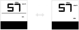
Km/mile:When the speed field displays S7, press the Increase (+) or Decrease (–) buttons to switchbetween km/h and mile/h or km and mile.
After this setting, press the Mode (i) button for shorter than 0.3 seconds to enter the settinginterface of light sensitivity.
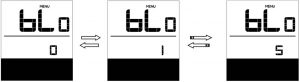
Light Sensitivity:When the speed field displays bL0, press the Increase (+) or Decrease (–) buttons to displaya figure between 0 to 5.
0 represents the shutdown of light-sensing function. As the figure increases, light sensitivitygradually increases.
After this setting, press the Mode (i) button for shorter than 0.3 seconds to enter the settinginterface of back light brightness.
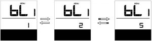
Back light Brightness:When the speed field displays bL1, press the Increase (+) or Decrease (–) buttons to display afigure between 1 to 5. The figure 1 represents the lowest backlight brightness while 5 indicates the highest backlight brightness.
After this setting, press the Mode (i) button for shorter than 0.3 seconds to enter the setting interface of automatic off time.
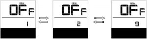
Automatic Off Time:When the speed field displays OFF, press the Increase (+) or Decrease (–) buttons to displaya figure between 1 to 9. This figure indicates the minute that it takes to automatically shutdown the display.
After this setting, press the Mode (i) button for shorter than 0.3 seconds to enter the settinginterface of maintenance warning.
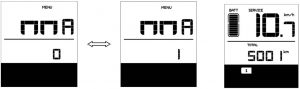
Maintenance Warning (inactive by default):When the speed field displays nnA, press the up or down to display 0 or 1. 0 disables the maintenance warning function while 1 enables the maintenance warning function.
After this setting, press the Mode (i) button for shorter than 0.3 seconds to enter the setting interface of password input.
Maintenance Warning Interface
The display will prompt maintenance necessity based on such information as the accumulated riding distance and the battery charge/discharge cycles.
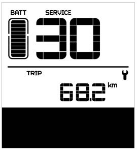
- When the accumulated riding distance exceeds 5,000 km (can be customised by the bicycle manufacturer), there will prompt, on the display, the symbol SERVICE and the sign of accumulated riding distance will flash for 4 seconds when the display is started up, indicating the bicycle needs maintenance.
- When the number of battery charge/discharge cycles exceeds 100 (can be customised by the bicycle manufacturer), there will prompt, on the display, the symbol SERVICE and the sign of battery will flash for 4 seconds when the display is started up, indicating the battery needs maintenance.
- Proceed in order parameter setting -> maintenance alert (MA) -> 0 to disable the maintenance alert function.
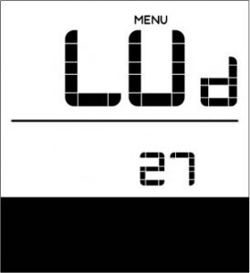
Wheel Diameter View:When the speed position displays Wd, the distance field displays the wheel diameter setting. This is set to 27 inches and cannot be adjusted. After viewing, press the Mode (i) button for less than 0.3 seconds to enter the setting interface of speed limit view.
Speed Limit View:When the speed field displays SPL, the distance field displays the bike’s speed limit. This is set to 25km/h and cannot be adjusted. After viewing, press the Mode (i) button for shorter than 0.3 seconds to enter the interface of battery communication.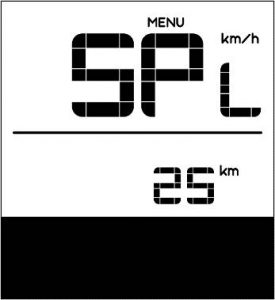
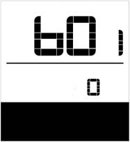
Battery Communication:On this screen, the speed field displays b01. The battery does not have a communication protocol, and the speedometer displays the “0”.
Double press the Mode (i) button for shorter than 0.3 seconds to exit the interface of battery communication settings.
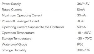
SPECIFICATIONS
TROUBLESHOOTING
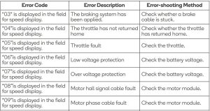
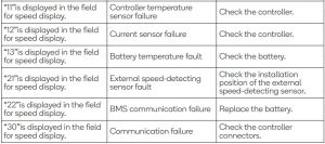
Error Code DefinitionsThe MAX-C966 display can give warnings on bicycle faults.When a fault is detected, the icon will be displayed on the LCD screen and there will be the following error code symbol in the speed display field:

Definitions of error codes are listed in the table below:
Need more information?We hope that this user guide has given you the assistance needed for a simple set-up. For the most up-to-date guide for your product, as well as any additional assistance you may require, head online to help.kogan.com.

[xyz-ips snippet=”download-snippet”]