Command ProCH245, CH255, CH260, CH270, CH270TFCH395, CH395TF, CH440, CH440TFOwner’s Manual
IMPORTANT:Read all safety precautions and instructions carefully before operating equipment. Refer to operating instruction of equipment that this engine powers.Ensure engine is stopped and level before performing any maintenance or service.Warranty coverage as outlined in the warranty card and on KohlerEngines.com. Please review carefully as it provides your specific rights and obligations.To maintain compliance with applicable emission regulations, exhaust system backpressure may not exceed limits which can be found on KohlerEngines.com. Search by Model No., then select the Specs tab.Kohler Engines has published CO2 values on KohlerEngines.com website.
Record engine information to reference when ordering parts or obtaining warranty coverage.Engine ModelSpecifi cationSerial NumberPurchase Date
Safety Precautions
WARNING: A hazard that could result in death, serious injury, or substantial property damage. CAUTION: A hazard that could result in minor personal injury or property damage.NOTE: is used to notify people of important installation, operation, or maintenance information.
WARNING
Explosive Fuel can cause fi res and severe burns.Do not fill fuel tank while the engine is hot or running.
 Gasoline is extremely flammable and its vapors can explode if ignited.Store gasoline only in approved containers, in well-ventilated, unoccupied buildings, away from sparks or flames. Spilled fuel could ignite if it comes in contact with hot parts or sparks from the ignition. Never use gasoline as a cleaning agent.
WARNINGRotating Parts can cause severe injury. Stay away while the engine is in operation.
Keep hands, feet, hair, and clothing away from all moving parts to prevent injury. Never operate the engine with covers, shrouds, or guards removed.
WARNINGCarbon Monoxide can cause severe nausea, fainting or death. Avoid inhaling exhaust fumes. Never run engines indoors or in enclosed spaces.

Engine exhaust gases contain poisonous carbon monoxide. Carbon monoxide is odorless, colorless, and can cause death if inhaled.
CAUTION Electrical Shock can cause injuryDo not touch wires while the engine is running.
WARNINGAccidental Starts can cause severe injury or death.Disconnect and ground spark plug lead(s) before servicing.
Before working on the engine or equipment, disable the engine as follows: 1) Disconnect spark plug lead(s). 2) Disconnect negative (–) battery cable from battery.
WARNING Hot Parts can cause severe burns.Do not touch the engine while operating or just after stopping.Never operate the engine with heat shields or guards removed.
WARNING: This product can expose you to chemicals including carbon monoxide and benzene, which are known to the State of California to cause cancer and birth defects or other reproductive harm. For more information go to www.P65Warnings.ca.gov.
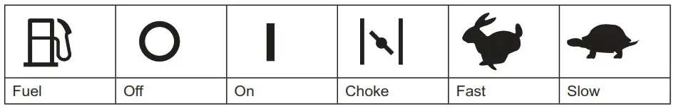
Symbols
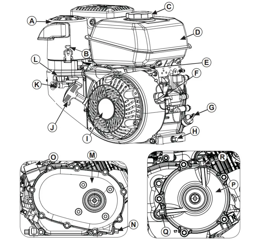
| A | Air Cleaner Cover | J | Fuel Shut-Off (and Ignition, if equipped) |
| B | Bail | K | Choke Lever |
| C | Fuel Cap | L | 2:1 with Clutch Reduction System (CH245, CH255, CH270, CH395, CH440) |
| D | Fuel Tank | M | Drain Plug |
| E | Throttle Lever | N | Gear Box Dipstick |
| F | On/Off Switch (if equipped) | O | 6:1 Reduction System (CH245, CH255, CH270) |
| G | Oil Drain Plug | P | 6:1 Reduction System (CH245, CH255, CH270) |
| H | Retractable Starter | Q | Oil Level/Drain Plug |
| I | Starter Handl | R | Oil Fill Plug |
See next page for exploded view of air cleaner systems.Visit KohlerEngines.com for service parts information and purchasing options.
| A | Quad-Clean™ Air Cleaner | J | CH270 Oil Bath Air Cleaner |
| B | Air Cleaner
Cover |
K | O-Ring |
| C | Bail | L | Foam Filter Cover |
| D | Precleaner | M | Foam Filter Support Plate |
| E | Paper Element | N | Foam Filter |
| F | Air Cleaner Base | O | Oil Retainer Ring |
| G | Low-Profi le Air Cleaner | P | Oil Reservoir Cup |
| H | Screw | Q | Oil Level Mark |
| I | Foam Element | R | CH395/CH440 Oil Bath Air Cleaner |
| S | Foam Element Kit |
Pre-Start Checklist
- Check oil level. Add oil if low. Do not overfi ll.
- Check fuel level. Add fuel if low. Check fuel system components and lines for leaks.
- Check and clean cooling areas, air intake areas, and external surfaces of the engine (particularly after storage).
- Check that air cleaner component and all shrouds, equipment covers, and guards are in place and securely fastened.
- Check spark arrestor (if equipped).
- If equipped with oil bath air cleaner, check the oil level in oil reservoir cup; add oil if below oil level mark; do not overfi ll; inspect for leaks. See Oil Bath Air Cleaner.
Starting
WARNINGCarbon Monoxide can cause severe nausea, fainting or death. Avoid inhaling exhaust fumes.
Never run engines indoors or in enclosed spaces.Engine exhaust gases contain poisonous carbon monoxide. Carbon monoxide is odorless, colorless, and can cause death if inhaled.
WARNING Rotating Parts can cause severe injury.Stay away while the engine is in operation.Keep hands, feet, hair, and clothing away from all moving parts to prevent injury. Never operate the engine with covers, shrouds, or guards removed.
NOTE: Choke position for starting may vary depending upon temperature and other factors. Once the engine is running and warm, turn to choke to OFF position.NOTE: Extend the starter cord periodically to check its condition. If the cord is frayed have it replaced immediately by a Kohler authorized dealer.NOTE: Do not crank the engine continuously for more than 10 seconds. Allow a 60 the second cool-down period between starting attempts. Failure to follow these guidelines can burn out the starter motor.NOTE: If the engine develops suffi client speed to disengage starter but does not keep running (a false start), engine rotation must be allowed to come to a complete stop before attempting to restart the engine. If the starter is engaged while the flywheel is rotating, starter pinion and flywheel ring gear may clash, resulting in damage to the starter.
- Turn fuel shut-off valve to ON position (if equipped).
- Turn engine on/off switch to ON position (if equipped).
- Start engine as follows:Cold engine: Place throttle control midway between SLOW and FAST positions. Place choke control into ON position. Warm engine: Place throttle control midway between SLOW and FAST positions. Return choke to OFF position as soon as the engine starts. A warm engine usually does not require a choke on.
- Retractable Start: Slowly pull starter handle until just past compression-STOP! Return starter handle; firmly pull straight out to avoid excessive rope wear from starter rope guide. Electric Start: Activate the starter switch. Release switch as soon as the engine starts. If the starter does not turn the engine over, shut off starter immediately. Do not make further attempts to start the engine until the condition is corrected. Do not jump start. See your Kohler authorized dealer for trouble analysis.
- Gradually return choke control to the OFF position after the engine starts and warms up. Engine/equipment may be operated during the warm-up period, but it may be necessary to leave the choke partially on until the engine warms up.
Cold Weather Starting Hints
1. Use proper oil for the temperature expected.2. Disengage all possible external loads.3. Use fresh winter-grade fuel. Winter grade fuel has higher volatility to improve starting.
Stopping
- If possible, remove load by disengaging all PTO-driven attachments.
- If equipped, move throttle control to the slow or idle position; stop the engine.
- If equipped, close fuel shut-off valve.
Angle of Operation
Refer to operating instructions of equipment this engine powers. Do not operate this engine exceeding the maximum angle of operation; see specifi cation table. Engine damage could result from insufficient lubrication.Engine SpeedNOTE: Do not tamper with the governor set to increase maximum engine speed. Overspeed is hazardous and will void the warranty.
High Altitude Operation
If this engine is operated at an altitude of 4000 ft. (1219 meters) or above, a high-altitude carburetor kit is required. To obtain high-altitude carburetor kit information or to find a Kohler authorized dealer, visit KohlerEngines.com or call 1-800-544-2444 (U.S. and Canada).This engine should be operated in its original confi duration below 4000 ft. (1219 meters).Operating this engine with the wrong engine confi duration at a given altitude may increase its emissions, decrease fuel efficiency and performance, and result in damage to the engine.
Carburetor Icing
NOTE: Running the engine with a cover positioned for cold weather operation in normal conditions can damage the engine.Carburetor icing can take place when certain combinations of temperature and humidity exist.The result of carburetor icing is rough running at idle or low speed as well as black or white smoke.To reduce the likelihood of carburetor icing, air cleaner cover can be rotated to draw warmer air from muffl er side. For cold weather operation, position air cleaner cover with snowfl ake decal out. For normal operation, position air cleaner cover with sun decal out.
Maintenance Instructions
|
WARNINGAccidental Starts can cause severe injury or death. Disconnect and ground sparkplug lead(s) before servicing. | Before working on the engine or equipment, disable the engine as follows: 1) Disconnect spark plug lead(s). 2) Disconnect negative (–) battery cable from battery. |
Normal maintenance, replacement or repair of emission control devices and systems may be performed by any repair establishment or individual; however, warranty repairs must be performed by a Kohler authorized dealer found at KohlerEngines.com or 1-800-544-2444 (U.S. and Canada).
Maintenance Schedule
After fi rst 5 Hours
- Change engine oil.Every 8 Hours
- Check oil bath air cleaner oil level in oil reservoir cup (if equipped).Every 50 Hours
- Change oil in 2:1 with Clutch Reduction System (CH245, CH255, CH270, CH395, CH440).Every 50 Hours¹
- Service/replace oil bath air cleaner foam fi lter or foam elements (if equipped).Every 50 Hours or Annually (whichever comes first)
- Service/replace Quad-Clean™ pre cleaner.Every 100 Hours or Annually¹ (whichever comes first)
- Clean low-profi le air cleaner element.
- Change engine oil.
- Clean cooling areas.Every 200 Hours
- Replace Quad-Clean™ air cleaner element.Every 300 Hours
- Replace low-profi le air cleaner element.
- Check fuel filters (tank outlet filter and in-line fi lter) and clean or replace if needed (if equipped).
- Change oil in 6:1 Reduction System (CH245, CH255, CH270).Every 300 Hours²
- Check and adjust valve clearance when the engine is cold.Every 500 Hours or Annually¹ (whichever comes first)
- Replace the spark plug and set gap.1. Perform these procedures more frequently under severe, dusty, dirty conditions.2. Have a Kohler authorized dealer perform this service.
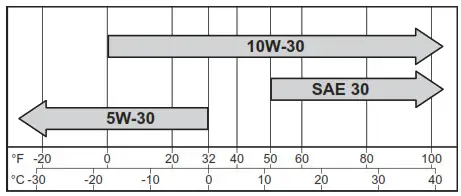
Oil Recommendations
We recommend use of Kohler oils for best performance. Other high-quality detergent oils (including synthetic) of API (American Petroleum Institute) service class SJ or higher are acceptable. Select viscosity based on air temperature at the time of operation as shown in the table below.
Check Oil Level
NOTE: To prevent extensive engine wear or damage, never run the engine with oil level below or above operating range indicator on dipstick.Ensure the engine is cool and level. Clean oil fi ll/ dipstick areas of any debris.
- Remove dipstick; wipe oil off.
- Reinsert the dipstick into the tube; rest on oil fi ll neck; turn counterclockwise until cap drops down to the lowest point of thread leads; do not thread cap onto the tube.a. Remove dipstick; check the oil level.For CH260/CH270 engines, oil level should be at the middle of the indicator on the dipstick.For all other models, oil level should be at top of the indicator on the dipstick.or b. Remove oil fi ll plug.For CH260/CH270 engines, oil level should be to the middle of fi ller neck threads. For all other models, oil level should be up to point of overfl owing fi ller neck.
- If oil is low, add oil to specifi ed level on dipstick or fi ller neck threads for the engine being serviced. See step 2.
- Reinstall dipstick or oil fi ll plug and tighten securely.
Change Oil
Change oil while the engine is warm.
- Clean area around oil fi ll cap/dipstick and drain plug.
- Remove the drain plug and oil fill cap/dipstick. Drain oil completely.
- Reinstall drain plug. Torque to 13 ft. lb. (17.6 N·m).
- Fill crankcase with new oil to specifi ed level on dipstick or fi ller neck threads for the engine being serviced. See Check Oil Level.
- Reinstall oil fi ll cap/dipstick and tighten securely.
- Dispose of used oil in accordance with local ordinances.
Oil Sentry™ (if equipped)
This switch is designed to prevent the engine from starting in a low oil or no oil condition. Oil Sentry™ may not shut down a running engine before damage occurs. In some applications, this switch may activate a warning signal. Read your equipment manuals for more information.
Reduction Systems (if equipped)
Some engines are equipped with a gear reduction system. Follow maintenance and oil change information specifi ed in this section and maintenance schedule.2:1 Reduction System (CH270) This reduction system is lubricated by engine crankcase oil. No special maintenance or service is necessary. Check and maintain engine oil level as outlined in Check Oil Level.2:1 with Clutch Reduction System (CH245, CH255, CH270, CH395, CH440) NOTE: Engines with this reduction system must be operated at 2400 RPM or higher under load when full gearbox engagement occurs. The operating engine under heavy loads below 2400 RPM, could result in clutch/gearbox failure from disc slippage/overheating and insufficlient engine cooling, not coveredunder normal warranty.
This reduction system uses a clutch assembly and chain and sprocket drive system, independent of, and separated from main crankcase lubrication. Check and maintain oil level using a dipstick in the gearbox case. Change reduction system oil at intervals in the maintenance schedule. Use 20W-40 or 20W-50 oil in this gearbox case. Oil capacity of this gearbox is 0.5 L (0.52 U.S. qt.).
- Drain old oil out through oil drain plug of the gear box cover, tip engine as required. Reinstall the drain plug and tighten it securely.
- The engine must be level. Add new 20W-40 or 20W-50 oil through oil dipstick hole on top of gearbox case until oil level is up to the bottom of the mark on the oil dipstick in gearbox case. Reinstall dipstick securely into gearbox cover.
6:1 Reduction System (CH245, CH255, CH270)This reduction system uses an internal pinion and ring gear system, independent of, and separated from main crankcase lubrication.Check and maintain oil level using oil level/ drain plug hole in gearbox case. Change reduction system oil at intervals in the maintenance schedule. The oil capacity of this gearbox is 0.12 L (0.13 U.S. qt.).
- Drain old oil out through oil level/drain plug, tip engine as required.
- The engine must be level. Add new oil through oil fi ll plug hole on top until oil level is up to the bottom of oil level/drain plug hole. Reinstall both plugs and tighten securely.
6:1 Reduction System (CH395, CH440)This reduction system is lubricated by engine crankcase oil. No special maintenance or service is necessary. Check and maintain engine oil level as outlined in Check Oil Level.
WARNINGExplosive Fuel can cause fi res and severe burns.Do not fi ll fuel tank while the engine is hot or running.Gasoline is extremely flammable and its vapors can explode if ignited. Store gasoline only in approved containers, in well-ventilated, unoccupied buildings, away from sparks or flames. Spilled fuel could ignite if it comes in contact with hot parts or sparks from the ignition. Never use gasoline as a cleaning agent.
NOTE: E15, E20, and E85 are NOT approved and should NOT be used; eff ects of old, stale, or contaminated fuel are not warrantable.Fuel must meet these requirements:
- Clean, fresh, unleaded gasoline.
- The octane rating of 87 (R+M)/2 or higher.
- Research Octane Number (RON) 90 octane minimum.
- Gasoline up to 10% ethyl alcohol, 90% unleaded is acceptable.
- Methyl Tertiary Butyl Ether (MTBE) and unleaded gasoline blend (max 15% MTBE by volume) are approved.
- Do not add oil to gasoline.
- Do not overfi ll fuel tank.
- Do not use gasoline older than 30 days.
Add Fuel
WARNINGExplosive Fuel can cause fires and severe burns.Do not fi ll fuel tank while the engine is hot or running.Gasoline is extremely flammable and its vapors can explode if ignited. Store gasoline only in approved containers, in well-ventilated, unoccupied buildings, away from sparks or flames. Spilled fuel could ignite if it comes in contact with hot parts or sparks from the ignition. Never use gasoline as a cleaning agent.
Ensure the engine is cool.
- Clean area around the fuel cap.
- Remove fuel cap. Fill to the base of filler neck.Do not overfi ll fuel tank. Leave room for fuel to expand.
- Reinstall fuel cap and tighten securely.
Fuel Line
A low permeation fuel line must be installed on carbureted Kohler Co. engines to maintain EPA and CARB regulatory compliance.Fuel ValveEngines are equipped with a fuel valve and integral screen filter located at the inlet of the carburetor. It controls and filters fuel fl ow from tank to carburetor. Clean fuel valve cup of debris.
- Remove two nuts, two screws, and a carburetor cover panel.
- Turn fuel valve lever to OFF position.
- Remove fuel valve cup. Remove O-ring and fi lter screen.
- Clean screen and fuel valve cup with solvent and wipe it off .
- Check screen and O-ring, replace if damaged.
- Reinstall O-ring followed by fuel valve cup.Rotate fuel valve cup until it is finger tight.Turn with a wrench 1/2 to 3/4 full turn.
- Turn the fuel valve to ON position and check forleaks. If the fuel valve leaks repeat steps 5 & 6.
- Tighten the fuel cap securely.
- Reinstall carburetor cover panel securing with hardware removed in step 1.
Spark Plugs
CAUTIONElectrical Shock can cause injury.Do not touch wires while engine is running.Clean out spark plug recess. Remove plug and replace.
- Check gap using a wire feeler gauge. Adjust gap, see specifi cation table for adjustment.
- Install plug into the cylinder head.
- Torque plug to 20 ft. lb. (27 N·m).
Air CleanerNOTE: Running the engine with a cover positioned for cold weather operation in normal conditions can damage the engine.NOTE: Operating an engine with loose or damaged air cleaner components could cause premature wear and failure. Replace all bent or damaged components.NOTE: Paper elements cannot be blown out with compressed air.
Quad-Clean™Move bails on air cleaner cover down; remove latches from under tabs on the base; remove the cover. or Turn air cleaner cover counterclockwise) to release tabs inside the cover from base; remove the cover.Precleaner:
- Remove pre-cleaner from the paper element.
- Replace or wash the cleaner in warm water with detergent. Rinse and allow to air dry.
- Lightly oil pre-cleaner with new engine oil; squeeze out excess oil.
- Reinstall the pre-cleaner over the paper element.
Paper Element:
- Separate cleaner from element; service pre leaner and replace the paper element.
- Install new paper element on the base; install pre-cleaner over the paper element. Position air cleaner cover for normal operation (sun decal out) or cold weather operation (snowfl ake decal out).Place latches under tabs on the base; lift up bails to secure cover. or Turn the air cleaner cover (clockwise) to secure tabs inside the cover in base.
Low-Profile
- Remove screw and air cleaner cover.
- Remove foam element from the base.
- Wash foam element in warm water with detergent. Rinse and allow to air dry.
- Lightly oil foam element with new engine oil; squeeze out excess oil.
- Reinstall foam element into base.
- Reinstall cover and secure with screw.
Oil BathSome engines are equipped with an oil bath air cleaner. Follow maintenance and oil change information specifi ed in this section and in the Maintenance Schedule.Move bails on air cleaner cover down; remove latches from under tabs on the base; remove the cover.
- Remove foam filter cover from oil reservoir cup. Remove foam filter support plate and foam filter or foam elements.
- CH270 engines: Replace or wash foam filter in warm water with detergent. Rinse and allow to air dry.CH395/CH440 engines: Replace or wash foam elements in warm water with detergent. Rinse and allow to air dry.
- Lightly oil foam filter or foam elements with new engine oil; squeeze out excess oil.
- Remove foam filter support plate and oil retainer ring from oil reservoir cup.
- Remove oil reservoir cup from the base. Empty oil from cup and wash cup in warm water with detergent. Rinse and dry cup.
- Make sure the O-ring is in place on air cleaner base. Set oil reservoir cup on the base.
- Fill oil reservoir cup up to oil level mark with the same grade of oil as in crankcase. See Oil Recommendations.

- Reinstall oil retainer ring and foam filter support plate in oil reservoir cup.
- CH270 engines: Reinstall foam filter on oil reservoir cup. Place foam filter support plate on filter. Reinstall foam filter cover. Make sure the O-ring is in place on top of the filter cover. CH395/CH440 engines: Reinstall taller foam element first, then shorter foam element on oil reservoir cup. Place foam filter support plate on elements. Reinstall foam filter cover. Make sure the O-ring is in place on top of the filter cover.
Position air cleaner cover for normal operation (sun decal out) or cold weather operation (snowfl ake decal out). Place latches under tabs on base; lift up bails to secure cover.
Breather Tube
Ensure both ends of the breather tube are properly connected.
Air Cooling
WARNING Hot Parts can cause severe burns.Do not touch the engine while operating or just after stopping.Never operate the engine with heat shields or guards removed.Proper cooling is essential. To prevent overheating, clean screens, cooling fi ns, and other external surfaces of the engine. Avoid praying water at the wiring harness or any electrical components. See Maintenance Schedule.
Repairs/Service Parts
We recommend that you use a Kohler authorized dealer for all maintenance, service, and replacement parts for the engine. To find a Kohler authorized dealer visit KohlerEngines.com or call 1-800-544-2444 (U.S. and Canada).
Storage
If the engine will be out of service for 2 months or more follow the procedure below.
- Add Kohler PRO Series fuel treatment or equivalent to the fuel tank. Run engine 2-3 minutes to get stabilized fuel into fuel system (failures due to untreated fuel are not warrantable).
- Change oil while the engine is still warm from operation. Remove spark plug(s) and pour about 1 oz. of engine oil into the cylinder(s).Replace spark plug(s) and crank engine slowly to distribute oil.
- If the engine is equipped with oil bath air cleaner, clean and oil foam filter or foam elements and replace oil in the oil reservoir cup. See Oil Bath Air Cleaner.
- Disconnect negative (-) battery cable.
- Store engine in a clean, dry place.
Troubleshooting
Do not attempt to service or replace major engine components, or any items that require special timing or adjustment procedures. This work should be performed by a Kohler authorized dealer.
|
Possible Cause |
||||||||
| Problem | No Fuel | Improper Fuel | Dirt In Fuel Line | Dirty Debris Screen | Incorrect Oil Level | Engine Overloaded | Dirty Air Cleaner | Faulty Spark Plug |
| Will Not Start | • | • | • | • | • | • | • | |
| Hard Starting | • | • | • | • | • | • | ||
| Stops Suddenly | • | • | • | • | • | • | • | |
| Lacks Power | • | • | • | • | • | • | • | |
| Operates Erratically | • | • | • | • | • | • | ||
| Knocks or Pings | • | • | • | • | ||||
| Skips or Misfires | • | • | • | • | • | |||
| Backfires | • | • | • | • | • | |||
| Overheats | • | • | • | • | • | • | ||
| High Fuel Consumption | • | • | • |
| Model | Bore | Stroke | Displacement | Oil Capacity(Refi ll) | Spark PlugGap | Spark PlugMaximum Angleof Operation(@ full oil level)* |
| CH245 | 2.7 in.(68 mm) | 1.9 in.(49 mm) | 10.8 cup. in.(177 ccs) | 0.63 U.S. qt.(0.60 L) | 0.030 in.(0.76 mm) | 25° |
| CH255 | ||||||
| CH260 | 2.8 in.(70 mm) | 2.1 in.
(54 mm) |
12.7 cup. in.(208 cc) | |||
| CH270CH270TF | ||||||
| CH395CH395TF | 3.1 in.
(78 mm) |
2.3 in.(58 mm) | 16.9 cup. in.(277 ccs) | 1.16 U.S. qt.(1.1 L) | ||
| CH440CH440TF | 3.5 in.(89 mm) | 2.7 in.(69 mm) | 26.2 cu. in.(429 ccs) |
*Exceeding maximum angle of operation may cause engine damage from insufficient lubrication.Additional specifi cation information can be found in the service manual at KohlerEngines.com.Any and all horsepower (hp) references by Kohler are Certifi ed Power Ratings and per SAE J1940 & J1995 hp standards. Details on Certifi ed Power Ratings can be found at KohlerEngines.com.
Emission Control System
Exhaust Emission Control System for models CH245, CH255, CH260, CH270, CH270TF, CH395, CH395TF, CH440, CH440TF is EM for U.S. EPA, California, and Europe. This engine is certifi ed to operate on gasoline.NOTE: Tampering with the engine and its emission control system voids the EPA Certifi cate of Conformity, ARB Executive Order, and EU type-approval.
 report this ad
References
[xyz-ips snippet=”download-snippet”]