![]()
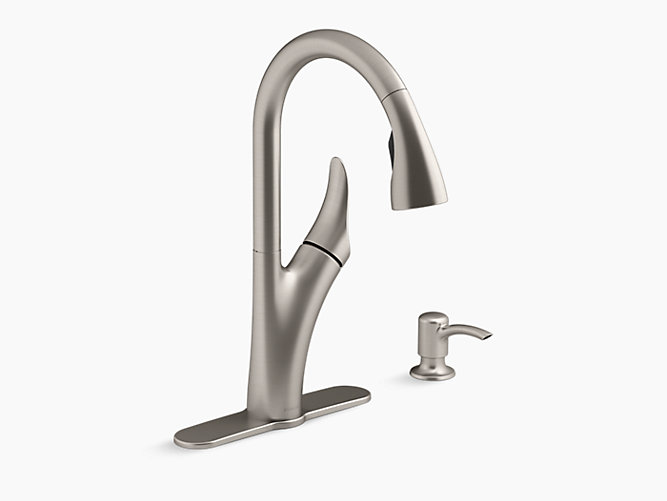
KOHLER Electronic Kitchen Faucet Installation Guide

K-R78035
IMPORTANT INSTRUCTIONS
 WARNING: When using electrical products, basic precautions should always be followed, including the following:DANGER: Risk of electric shock. Connect only to a circuit protected by a Ground-Fault Circuit-Interrupter (GFCI)*.WARNING: Risk of electric shock. Grounding is required. A licensed electrician should make all electrical connections.WARNING: Risk of electric shock. Disconnect power before servicing.WARNING: Risk of injury or property damage. Please read all instructions thoroughly before beginning installation.CAUTION: Risk of property damage. The faucet spout contains a magnet. Do not allow items susceptible to electromagnetic damage to come into close proximity to the spout.
Follow all plumbing, electrical, and building codes.
*Outside North America, this device may be known as a Residual Current Device (RCD).
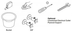
Tools and Materials
Important Information
WARNING: Risk of fresh water contamination. This faucet contains back-siphonage protection. Do not remove any internal components.
CAUTION: Risk of product damage. This product contains sensitive electronic components. Do not store open containers of chemical or cleaning products near this product. Cleaning rags or sponges must be rinsed with fresh water before storage.
IMPORTANT! Do not use a switch-controlled outlet (typically used for garbage disposals) to provide power to the faucet.
- Observe all local plumbing and building codes.
- Provide a constant unswitched 120 VAC electrical outlet located below the sink within 4’ (1.2 m) of the control box (optional).
- Turn off the water supply.
- For new installations, assemble the faucet to the sink before installing the sink.

Before You Begin
CAUTION: Risk of restricted water flow and product damage. Supply hoses must not be taut, kinked, or twisted during installation.
IMPORTANT! Risk of restricted water flow. The outlet hose must not be taut or kinked when installed.
NOTICE: When locating the valve box bracket make sure that the spray hose weight will not interfere with the valve box or wire connections.
NOTE: Allow adequate clearance for servicing.
- Before installing the faucet make sure the cabinet area under the sink can accommodate all of the required components.
- Consider loose fitting the connections covered in the following steps to make sure the bracket location allows enough clearance for the operational use of the spray hose and weight
- If installing the optional power supply, make sure there is an unswitched 120V outlet within reach.
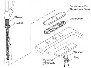
1. Install the Faucet
NOTE: Handle orientation is designed to be on the right.
- For Three-Hole Sinks: Install the gasket, foam side down. Place the escutcheon and undercover over the sink holes. Insert the faucet through the escutcheon and the mounting surface with the handle on the right.
- For Single-Hole Sinks: Install the gasket, foam side down. Insert the faucet through the mounting surface with the handle on the right.
- For thin gauge stainless steel sinks, consider installing a 1/2” (13 mm) plywood support (not supplied).
- Slide the washer and ring over the knurled hose, then over the other hoses and wires, and up to the shank.
- Thread the ring onto the shank until the washer contacts the underside of the sink.
- Make sure the faucet is positioned correctly.
- Use a Phillips screwdriver to securely tighten the screws.
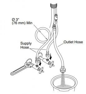
2. Connect the Hoses
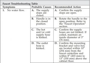
CAUTION: Risk of restricted water flow and product damage. Supply hoses must not be taut, kinked, or twisted during installation. If the supply hoses must be coiled, maintain an inside diameter of 3″ (76 mm).
Connect the Supplies
- Connect and tighten the supply hoses to the supply stops.
- Place a bucket under the outlet hose.
- Turn on the water supplies.
- Flush hot and cold water into a bucket for 1 minute to remove any debris.
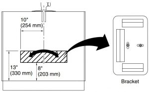
3. Mount the Bracket
NOTICE: The bracket must be installed vertically.
NOTE: Allow adequate clearance for servicing.
NOTE: If using the optional AC adapter (not supplied) consider the distance to the nearest electrical outlet when positioning the bracket within the specified range.
- Locate the bracket within 10″ (254 mm) from the faucet centerline.
- The bottom of the bracket should also be between 8″ (203 mm) and 13″ (330 mm) above the cabinet floor.
- Secure the bracket with the provided mounting screws. If installing on drywall, use appropriate anchors (not supplied).
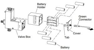
4. Install the Batteries
- Disconnect the green connector from the valve box.
- Slide the battery holder off the valve box.
- Press the tabs to remove the cover from the battery holder.
IMPORTANT! Do not use rechargeable or lithium-ion batteries.
- Insert six AA batteries into the battery holder.
- Reinstall the cover on the battery holder with the flat part of the green connector facing the front of the holder.
- Slide the battery holder back onto the valve box.
IMPORTANT! Do not reconnect the green connector until instructed to do so.
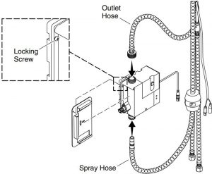
5. Install the Valve Box
IMPORTANT! Risk of restricted waterflow. The outlet hose must not be taut or kinked when installed.
NOTICE: Handtighten the outlet hose connector. Do not use a pliers or a wrench.
- Thread the outlet hose onto the valve inlet.
- Slide the valve box into the mounted bracket.
- Tighten the locking screw to secure the valve box to the bracket.
- Connect the spray hose to the valve box outlet. It will click into place when the connection is secure.
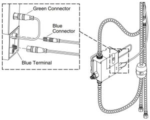
6. Connect the Wires
IMPORTANT! Do not connect the green connector until all other wires have been attached.
- Connect the blue connectors to the blue terminals on the valve box. The white lines on the connectors should face the front of the valve box.
- Connect the green connector from the valve box to the battery holder.
NOTE: A LED light will flash on the faucet sensor for fifteen seconds to indicate a proper installation.
- If installing the optional power supply (not supplied), plug the power cord into an unswitched 120 VAC outlet and connect it to the valve box. A green LED on the valve box will illuminate when the power supply is connected.

7. Complete the Installation
Position the Spray Hose Weight
NOTICE: Make sure that the spray hose weight will not interfere with the valve box or wire connections.
- Loosely attach the weight to the spray hose.
- Position the weight approximately 11″ (279 mm) from the bottom of the hose loop.
- Secure the spray hose weight in place by tightening the two screws.
- Extend and retract the spray hose to check for smooth operation.
Check for Leaks
- Ensure all connections are tight.
- Turn on the water supplies, and check all connections for leaks.
- Test the faucet for proper operation. Refer to the ″Faucet Operation″ section.
Faucet Operation
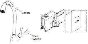
- Rotate the handle outward to the open position to start water flow.
- Adjust the handle to the desired water temperature.
- Wave your hand under the spout to turn the water OFF.
- Wave your hand under the spout again to restart the water flow.
NOTE: For extended periods of nonuse, the handle should be returned to the closed (upright) position.
Valve Box LED Indicators
- Green LED: Indicates that the AC plug is installed and connected.
- Red flashing LED: Indicates low batteries.
Features
- Automatic shut-off: After 4 minutes of inactivity, the water will automatically shut OFF.
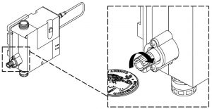
Manual Sensor Override
- In the event of power loss, the sensor function can be bypassed by engaging the manual override feature on the valve box.
- Turn clockwise to engage the bypass and counterclockwise to disable the bypass.
- Once the manual override is engaged, the faucet can then be operated manually.
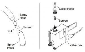
Cleaning the Screens
Sprayhead Screen
- Turn the handle to the closed position.
- Disconnect the nut at the end of the spray hose.
- Remove and clean the screen inside the spray hose.
- Reinsert the screen and reconnect the spray head.
Valve Box Inlet Screen
- Turn the handle to the closed position.
- Disconnect the outlet hose from the valve box.
- Remove and clean the inlet screen from inside the valve box.
- Reinstall the inlet screen and reconnect the outlet hose.
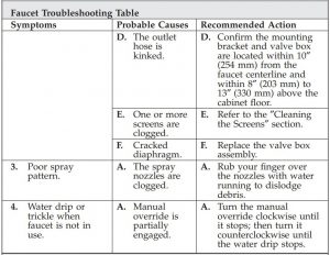
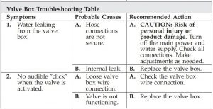
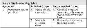
Troubleshooting
CAUTION: Risk of product damage. This product contains sensitive electronic components. Use care not to damage pins and connectors during troubleshooting.
NOTE: For service parts information, visit your product page at www.kohler.com.

Warranty
KOHLER® Electronic Faucets, Valves and ControlsFIVE-YEAR LIMITED WARRANTY
Kohler Co. warrants that its electronic faucets, valves and controls will be free of defects in material and workmanship during normal residential use for five years from the date the product is installed. This warranty applies only to electronic faucets, valves and controls installed in the United States of America, Canada and Mexico (″North America″).
If a defect is found in normal residential use, Kohler Co. will, at its election, repair, provide a replacement part or product, or make appropriate adjustment where Kohler Co.’s inspection discloses any such defect. Damage caused by accident, misuse, or abuse is not covered by this warranty. Improper care and cleaning will void the warranty*. Proof of purchase (original sales receipt) must be provided to Kohler Co. with all warranty claims. Kohler Co. is not responsible for labor charges, installation, or other incidental or consequential costs other than those noted above. In no event shall the liability of Kohler Co. exceed the purchase price of the faucet, valve or control.
If the electronic faucets, valves or controls are used commercially or are installed outside of North America, Kohler Co. warrants that the faucet, valve or control will be free from defects in material and workmanship for one (1) year from the date the product is installed, with all other terms of this warranty applying except duration.
If you believe that you have a warranty claim, contact your Home Center, Dealer, Plumbing Contractor or E-tailer. Please be sure to provide all pertinent information regarding your claim, including a complete description of the problem, the product, model number, the date the product was purchased, from whom the product was purchased and the installation date. Also include your original invoice.
For other information, or to obtain the name and address of the service and repair facility nearest you, write Kohler Co., Attn: Customer Care Center, Kohler, Wisconsin 53044 USA, or by calling 1-800-4-KOHLER (1-800-456-4537) from within the USA and Canada, and 001-800-456-4537 from within Mexico, or visit www.kohler.com within the USA, www.ca.kohler.com from within Canada, or www.mx.kohler.com in Mexico.
THE FOREGOING WARRANTIES ARE IN LIEU OF ALL OTHER WARRANTIES, EXPRESS OR IMPLIED, INCLUDING BUT NOT LIMITED TO THE IMPLIED WARRANTIES OF MERCHANTABILITY AND FITNESS FOR A PARTICULAR PURPOSE.
KOHLER CO. AND/OR SELLER DISCLAIM ANY LIABILITY FOR SPECIAL, INCIDENTAL OR CONSEQUENTIAL DAMAGES. Some states/provinces do not allow limitations on how long an implied warranty lasts or the exclusion or limitation of such damages, so these limitations and exclusions may not apply to you. This warranty gives the consumer specific legal rights. You may also have other rights that vary from state/province to state/province. This warranty is to the original consumer purchaser only, and excludes product damage due to installation error, product abuse, or product misuse, whether performed by a contractor, service company, or the consumer.
This is Kohler Co.’s exclusive written warranty.
*Never use cleaners containing abrasive cleansers, ammonia, bleach, acids, waxes, alcohol, solvents or other products not recommended for chrome. This will void the warranty.
USA/Canada: 1-800-4KOHLERMéxico: 001-800-456-4537kohler.com
![]()
©2016 Kohler Co.
References
[xyz-ips snippet=”download-snippet”]