![]()
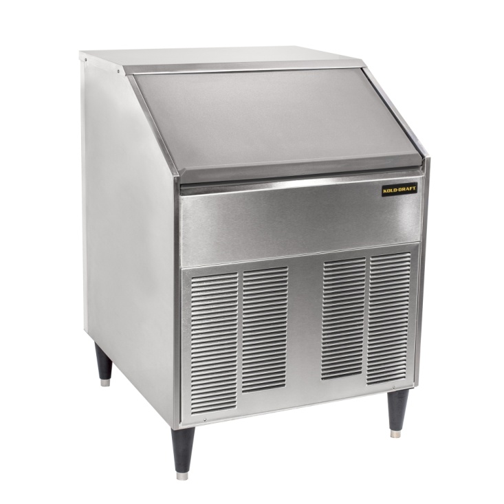
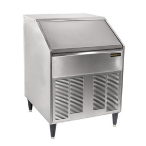
KOLD DRAFT SC200 Series Ice Machine Installation Guide

Kold-Draft International, LLC1525 East Lake RoadErie, PA 16511-1088 U.S.A.Phone: (800) 840-9577Fax: (800) 548-9392www.kold-draft.com
This manual is updated periodically. Visit http://www.kold-draft.com/resources/literature.php for the latest version.
KOLD-DRAFT INTERNATIONAL, LLCA DIVISION OF THE LEGACY COMPANIES, LLC
Installation & Operation ManualSC200 Series Ice MachineCopyright2016 KOLD-DRAFT INTERNATIONAL, LLCUnauthorized reproduction of this manual is freely permitted for all purposes except for monetary gain.
It is not guaranteed that this service manual is up to date, technically correct, complete, or free from writing problems or that the product is free from minor flaws or that it meets the needs of the customer.June 2021
Safety Warnings and Information
Special attention should be given to potential hazard labeling on the equipment and the signal words and symbols that are used throughout this manual. They may also be used to alert against unsafe practices.
 WARNING:Indicates a potentially hazardous situation that may result in serious injury or death.
CAUTION: Indicates a potentially hazardous situation that may result in personal injury. The situation may also result in equipment or property damage.
NOTE: Indicates installation, operation, or maintenance information which is important, but not related to personal injury or property damage.
NOTE:
- Check for freight damage before proceeding with the equipment installation. Be sure to inspect the equipment carefully for any damage that may not have been evident on the outside of the carton. Contact the freight carrier immediately to report any damage and file a claim. Have carrier note the damage on the bill of lading. Call Kold-Draft with your claim number to arrange replacement or repair.
- Read the entire manual before installing, operating or servicing the machine.
- To ensure optimal efficiency and productivity follow these installation instructions exactly.
- All machines have been tested and adjusted for correct performance at the factory.
- Knowledge of proper installation and service procedures is essential for the safe operation and maintenance of KOLD-DRAFT equipment. Refer all installation and service work to qualified technicians.
- This equipment must be installed in compliance with the applicable federal, state/province, and/or local plumbing, electrical, and health/sanitation codes and requirements.
- Always disconnect the power supply before servicing the equipment or when the equipment will not be used for a period of time. Some circuits remain energized when the machine is switched off.
- Never operate equipment that has been damaged or does not have all the protective covers in place.
- Never operate equipment that has been altered from the original KOLD-DRAFT specifications.
WARNING:Use only genuine KOLD-DRAFT replacement parts, Use of non-approved parts when servicing KOLD-DRAFT equipment may create a safety hazard, cause equipment damage, property damage and will void the warranty.
Ice Maker Identification
Model Number Key

Date Code Key

NOTE: The serial number plate is located in the condensing unit compartment, on the left side wall. A complete model number and date code are essential for the accurate identification of the ice machine and proper selection of replacement parts.
Installation Information
WARNING:
- Instruct all personnel in the proper use of the equipment.
- Clean up any liquid spills immediately.
- Always install equipment on a stable and level surface.
- All models are intended for indoor use only. Do not install the equipment in unprotected outdoor areas.
- Do not install the equipment in wet areas.
- Do not locate the equipment near any heat source, in direct sunlight, in high ambient areas, or without proper clearance for ventilation. Placing equipment in these locations will result in reduced capacities, high system pressures and may cause equipment failure.
NOTE: Each Kold-Draft ice machine has successfully completed a quality assurance test and has been factory inspected before shipping.
UnpackingUnpacking a KOLD-DRAFT machine can be done by prying off the boards that are holding the cardboard box to the shipping pallet. The box can then be lifted vertically to expose the machine.
Remove all packaging materials from the ice machine and protective film from the stainless steel surfaces.
Carton Contents
- Kold-Draft SC200 Series Ice Machine
- Warranty card attached to the front of the machine(must be fully completed and returned to the factory within 15 days of installation to register this product and to initiate warranty coverage.)NOTE:Failuretoreturnthis registration form will void your warranty.
- Installation & Operation Manual. Leave these with the owner/user.
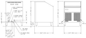
Installation Requirements
- The ice machine must be installed indoors and the location should be free of airborne contaminates including any corrosive elements.
- Ambient air temperatures at the install location must be between 45°F (7°C) and 90°F (32°C).Ambient temperatures higher than the maximum specification will result in reduced capacities and high system pressures in air-cooled models. Temperatures lower than the minimum may cause the machine to be unable to eject the ice from the evaporator. Ambient temperatures less than 60°F (15°C) may cause the bin probe to malfunction.
- The machine may be built into a cabinet. Clearance is not required around the top and sides, but must be provided in back for plumbing and electrical connections and in front for free flow of air in and out of the condensing unit compartment.
- Do not install air cooled units in closets or small rooms where the free flow of air to the unit is restricted.
- The location must not be near heat generating equipment.
- The location must not be near anything that can contaminate it or the ice inside.
- The ice machine should be mounted on the legs provided and leveled by screwing the leg adjusters in or out as required. If the legs are not used, shim the bottom of the machine as required to make it level. Seal any gaps at the floor with approved sealant or use cove molding for larger gaps. Make sure the lower front cover remains removable for service.
- The location must be capable of supporting the weight of the ice machine, with a full bin of ice.
Plumbing
- The drain hose or pipe must not be reduced in size from the machine to the drain. The building drain must be able to accommodate all the drain water from the ice machine operation.
- Individual drains will not be directly connected to a common manifold, drain or standpipe. If individual drains are to be discharged into a common manifold, drain or standpipe, a minimum 1.5” (38mm) air gap must be provided at each connection. This is to prevent any backflow of drain water into the ice maker or ice bin.NOTE: Installation must provide adequate backflow prevention to comply with applicable federal, state and local codes.
- Drain lines will be installed with a minimum drop of 1/4” per ft. (2.1cm per meter) run. Ice machine drains and bin drains may be insulated to prevent condensation.
- Water supply temperature must be between 45°F (7°C) and 90°F(32°C). Do not connect the ice machine to a hot water supply line. Insulate the water line from sources of heat for greater operating efficiency. Supply water temperatures higher than the recommended maximum will cause reduced capacities.
- The water supply must be potable, not laden with sediment, and have free chlorine levels no greater than 0.2ppm. Supplies with higher chlorine levels should be filtered.There are no specific requirements for water treatment, but the use of water conditioning may increase the intervals between cleaning operations and overall machine life.Please consult a local water conditioning supplier for specific recommendations for your area.
- A minimum 20 psig(dynamic) water supply pressure is required for proper operation of the ice maker water valve. Please note that on liquid cooled ice machines, where the same water supply is used for both condenser cooling and the potable water supply, the demand for condenser coolant may cause the supply pressure to drop. This is most notable at the time of peak load, at the beginning of the freeze cycle. The maximum water supply pressure is 100 psig (0.6 MPa).If a water pressure regulator is used, the recommended setting is 30 to 50 psig (0.2 MPa to 0.3 MPa) dynamic.
- All water lines must be purged before connection to the ice machine.
Electrical
WARNING: Failure to comply with these regulations may cause serious injury or death and cause damage to the machine and its surroundings.
CAUTION: Switching the machine “off” does not de-energize all circuits. Always disconnect power before servicing.
- All KOLD-DRAFT models are intended to be installed with a permanent connection to the field electrical supply. See rating plate on the back of the machine for power supply requirements.
- Each ice maker must be connected to a separate protected circuit with no other loads.
- Fused disconnects, installed adjacent to each ice maker, are recommended and may be required by local codes. These components must be supplied by the installer.
- Electrical service must fall within the voltage tolerances listed below:

Maximum Overload Protection must be no greater than specified. The minimum circuit ampacity specified does not indicate a typical running current value. Use the minimum ampacity value for sizing branch circuit conductorsup to 26 feet (8 meters) in length. For a conductor length over this length, increase the wire gauge as required by code.
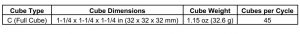
Ice Cube Information
Operation
Initial Start Procedure
- Be sure that the on-off switch is in the “off” position and the ice-clean switch is in the “ice” position.
- Make sure all water lines and hoses are securely connected, turn on water supply and check for leaks.
- Move the on-off switch to the “on” position and observe the water plate opening. Any water in the tank will then be drained. The compressor will turn on, the water plate will close and the sump tank will start to fill.
- Also, observe that the water pump is circulating water through the system. A momentary sucking cavitation sound is normal at the beginning of the process when the water level is low. Check that there are no water leaks from the hoses or water tank into the bin.
- The machine will begin to make ice.
- When ice is available, test the bin probe adjustment by holding ice against it.Adjust the controller, if required. Code 90 indicates ice bin full, a cold bin probe will shut down the ice machine right after the next harvest is complete.
- Replace and secure all the cabinet panels.
- Discard all the ice from the start-up cycles, then clean and sanitize the ice storage bin according to the instructions provided.
Ice Machine Re-StartAt power up, in the ice making mode, the electronic control will monitor the conditions and operate in the following manner:
If the evaporator temperature is colder than the harvest termination temperature at start up, the water plate will open (lower).
If there is an obstruction preventing the water plate from closing, it will re-open (lower)If the evaporator temperature is warmer than the harvest termination temperature and the water plate is open, it will close (raise).
Controls and Adjustments
On-Off Switch: Used to turn the ice machine on or off.
CAUTION: Switching the machine “off” does not de-energize all circuits. Always disconnect power before servicing.
Ice-Clean Switch: The “Ice” position signals the controller to provide full operation of the ice machine. The “Clean” position will exclude operation of the compressor and condenser fan motor (air cooled models) and provide operation required for the cleaning procedure.
Defrost Button: Push this button anytime lowering the water plate and/or forcing the ice machine into the defrost mode is desired. The water plate will remain down for four minutes and then return to normal operation. Pushing the button again, while the plate is down, will immediately return the machine to normal operation.
Float Switch: Closes water inlet valve when water sump is full
Evaporator Probe: Provides evaporator temperature information to the control board to begin and end the defrost cycle. Adjust the left potentiometer on the control board to determine ice cube fullness. Turn CW to extend the freeze time and CCW to shorten it.
NOTE: Ice cubes should never be frozen completely full. A small dimple in each cube indicates a proper adjustment. Making cubes without a dimple will reduce ice machine capacity and may cause damage to the water plate and operating mechanism.
Bin Probe: This probe will sense contact with the ice, when the bin is full and turn off the ice machine. When ice is used and is no longer in contact the probe, it will signal the control to turn on the ice machine. When the ice machine is off due to a full bin, the code 90 indicator will be lit on the control board.Contact with ice should turn off the ice machine within one minute.
If adjustment is required, hold ice against the probe. Turn the right side potentiometer on the control board CCW to shut off the machine within one minute. CW adjustment is required if the ice machine shutsdown, as if the bin is full, when ice has not contacted the probe.
Plate-Up Switch: This switch limits the upward travel of the water plate. It opens to de-energize the actuator motor, by way of an operator,when its shaft is in the full up (closed) position.
This switch also provides a way for the controller to determine that the plate is blocked. When the plate is closing, the controller provides a time limit for this switch to open. If the time limit is exceeded, the controller will reopen the water plate to clear it. This will repeat until the surface is clear.
Plate-Down Switch: This switch limits the downward travel of the water plate. It opens to de-energize the actuator motor, by way of an operator,when its shaft is in the full down (open) position.
Sequence of OperationThe following tables describe the general states and sequence of operation for the ice machine models in ice-making mode with an additional table depicting the status when the ice bin is full and the cleaning mode. The charts provide information about the inputs to the controller and the corresponding AC outputs associated with each part of the ice making cycle.
Note:
- Abnormal operation of the ice machine is covered in the Fault Condition section of the manual.
Ice Making Sequence
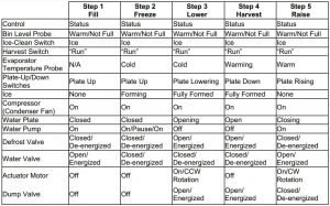
Description of Each ProcessThe following sequence begins with the cuber as shipped from the factory with the water plate(s) closed and ready to begin a normal ice making cycle.
Fill: The water solenoid valve will be energized until the water level switch indicates that the sump is full. The water pump will run as the water is filling the sump.If the water plate is open, it will close before the pump starts. The water solenoid valve will remain de-energized until the following cycle starts. No additional water will be introduced during the freeze cycle.
Freeze: The freeze cycle begins as the sump is filling with water. The water level in the sump will drop as the ice cubes are formed.
Lower: When the evaporator outlet reaches the set temperature point the machine will go into harvest.The water plate begins to open and the defrost valve is energized to allow hot gas to circulate through the evaporator. The evaporator warms to begin the ice harvest.The dump valve is also open at this time, to drain the remaining mineral laden water from the sump. When fully open, the water plate will stop.
Harvest: The evaporator continues to warm until the ice falls out onto the water plate and into the ice bin. When the evaporator reaches a pre-set temperature, indicating that all the ice has dropped out, the defrost valve is de-energized and the water plate begins to close.
Raise: The water solenoid valve will be energized,as the water plate closes, to begin filling the sump for the next ice-making cycle. When fully closed, the water plate will stop and the water pump will be energized. The evaporator cools and begins to remove heat from the water to make the next batch of ice.
Ice Bin Full: When the level of ice reaches the bin probe, the ice maker stops automatically, and it remains off until the bin probe warms up when the ice level is lowered.
Cleaning Mode: All of the operational components except refrigeration are able to function with the make ice/clean switch in the clean position. Simply placing this switch in the cleaning position does not complete the cleaning and sanitizing of the cuber. Instructions pertaining to the cleaning of a machine can be found on page 12 of this manual.
Note: The frequency of the need for cleaning is determined by the supply water characteristics. The cuber should be cleaned no less frequently than once each 6 months, and it may require more frequent cleaning. The requirement for sanitizing frequency may be contained in local health code regulations.
Water Plate Closure Problems: If the water plate is not able to close due to ice remaining on the water plate surface, the plate will reopen until it is clear.
Shutdown-High Pressure: All models are provided with a high pressure cutoff, which interrupts power to the compressor and to the condenser fan motor, if so equipped, when the high-side pressure rises to the cutoff setting. The high pressure cutoff will automatically reset, restoring power when the pressure drops. When this happens it is important to determine the cause of the high pressure and correct it.
Maintenance and Service Information
Ice Machine Cleaning ProcedureIt is recommended to perform this cleaning procedure a minimum of twice per year.
- While the ice machine is operating, wait until the ice falls out of the evaporator and the water plate fully returns to the up position. Turn the machine off and empty the storage bin. Move the Ice-Clean Switch to the “Clean” position and turn the ice machine on.
- While the water plate is filling pour 3 fl. oz. (90 mL) of Kold-Draft nickel-safe ice machine cleaner (Kold-Draft part no. 500023) into the water sump though the opening along its front edge.
- The cleaning solution will circulate for 20 minutes and then drain. The sump will fill again, with the water circulating and then drain. This will repeat 3 more times, to be sure all the cleaning solution is rinsed out of the machine and then stop. When this process is complete, turn the machine off.
- Mix a sanitizing solution containing 0.5 ounce (15 mL) 5-1/4% sodium hypochlorite (household bleach or equivalent) and 1 gallon (3.8 liter) warm clean water.
- Pour the sanitizing solution into the sump. Leaving the Ice-Clean Switch in the “Clean” position turn the machine on.
- The sanitizing solution will circulate for 20 minutes and then drain. The sump will fill again, with the water circulating and then drain. This will repeat 2 more times, to be sure all the sanitizing solution is rinsed out of the machine and then stop.
- While these solutions are circulating in the ice machine, clean and sanitize all accessible surfaces of the ice machine and bin. Mix a cleaning solution as follows: 8 tablespoons (1/2 cup) (96g) baking soda and 1 gallon (3.8 liter) of warm clean water. Mix a sanitizing solution as follows: 2 teaspoon (10 mL) 5-1/4% sodium hypochlorite and 1 gallon (3.8 liter) of warm clean water. Use clean towels to apply these solutions and rinse well when done.
- After all cleaning, sanitizing and rinsing has been completed turn the machine off. Move the Ice-Clean Switch to the “Ice” position. Check for proper operation of the machine and dispose of the first batch of ice
Cleaning Mode Start UpAt power up in the wash mode the electronic control will monitor the following criteria: If the water plate is not in the full up (closed) position at start up, the controller will close the plate.
If there is ice on the surface of the water plate, preventing it from closing, the controller will reopen the plate to clear it.
Storage and Winterization
Clean and sanitize the ice machine.Disconnect the electric power supply.Disconnect water and drain lines.Remove and empty the water sump.Open water valve and dump valve and blow compressed air through all lines.Remove and drain the water plate assembly.Reassemble water plate assembly and water sump.Replace all cabinet panels.
Removal from Service
When the ice maker is determined to be no longer useable please be sure that it is rendered safe for storage or disposal. All applicable recycling measures should be exercised to avoid injury and harm to the environment.
The manufacturer and/or seller is not responsible for any harm to people, animals, property, and the environment caused by incorrect installation and/or disposal.
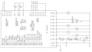
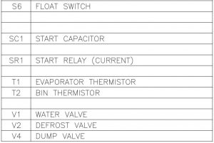
Wiring Diagram
THE ELECTRONIC CONTROL WILL MONITOR FOR THE FOLLOWING CONDITIONS AND PREVENT THE ICE MACHINE FROM OPERATING AS REQUIRED TO PREVENT DAMAGE.
LED 10– EVAPORATOR PROBE NOT CONNECTED OR DAMAGED.
LED 20WATER PLATE HAS RE-OPENED 13 CONSECUTIVE TIMES WITHOUT STARTING A FREEZE CYCLE.
LED 30– FREEZE CYCLE EXCEEDS 45 MINUTES. FLASHES AFTER 3 CONSECUTIVE 45-MINUTE CYCLES.
LED 40FREEZE CYCLE SHORTER THAN 5 MINUTES. FLASHES AFTER 3 CONSECUTIVE ATTEMPTS AND CIRCULATES WATER. SOLID AFTER 6 CONSECUTIVE ATTEMPTS.
LED 60WATER FILL EXCEEDS 3 MINUTES.
LED 70CAM SWITCH FAULT-BOTH ARM-UP AND ARM-DOWN SWITCHES ARE ENGAGED AT THE SAME TIME
LED 80NO JUMPER ON J2. (NO FUNCTIONAL SIGNIFICANCE)
LED 90BIN FULL-BIN PROBE’S TEMPERATURE IS LESS THAN THE BIN ADJUSTS SET POINT


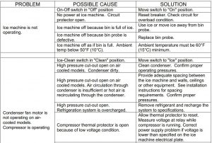
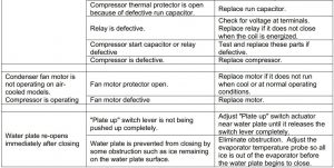
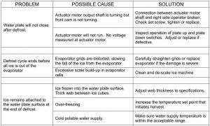
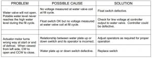
Problems and Solutions

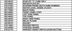
102148101SC200 EVAPORATOR KIT-C CUBE


CONTROL BOX ASSY


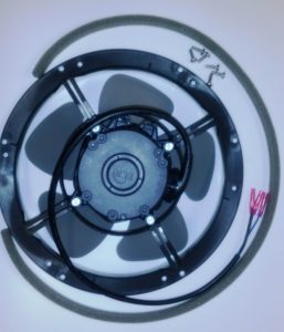
102148301SC200 FAN ASSY .KIT

PARTS LIST
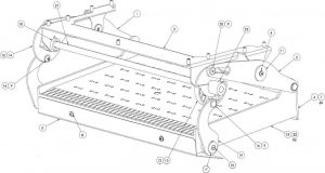
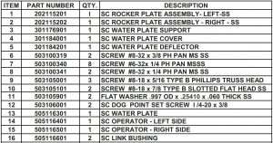
SC200 WATER PLATE & OPERATION ASSEMBLY
DOC# 307108601

SC201AC Parts List

References
[xyz-ips snippet=”download-snippet”]