KoPa TC200 All-in-one Smart Display camera User Manual
Chapter 1 Notes and Safety Requirements
Cautions and Notes
- To avoid danger or damage incurred to the lens, do not touch the lens or sensor directly with your fingers.
- To avoid failure or electric shock hazard and so on, do not disassemble or modify the internal structure of the device.
- Do not plug in or unplug the USB port or the HDMI port when hands are wet.
- Do not use alcohol and other organic solvents to clean.
- If the lens or sensor is dirty or damp, you should better use dry and non-linen fabric orprofessional lens tissue to wipe them. To avoid scratches on the surface, do not touch the lens with your fingers. Wipe the lens or sensor lightly.
- The products are not specifically designed for an outdoor use. Do not expose it to outdoor environment without any protection. Excessive temperature and humidity will damage the lens. Please avoid using the product under the following environment: high temperature or high humidity environment, places with direct sunlight, dirt or vibration and places near heat source.
- Please use and store in the following environment:Operating temperature :0℃~ 40℃Storage temperature:-20℃~ 60℃Operating Humidity :30~60%RHStorage Humidity:10~80%RH
- If any foreign matter, water or liquid enter into the device by accident, disconnect the USB cable immediately. Please send it to the maintenance center and do not use the hair dryer to dry it by yourself.
- To prevent microscope from being tripped over or dropped, please put away the device’s USB cables in use or standby.(10) To avoid electric shock by accident, please power off microscope before you move your computer or laptop.
- The cleanliness of the device lens will directly affect clarity degree of contents from the computer screen during preview. Problems like various circles or spots on the screen may mostly be incurred by dirt on the lens. When cleaning, please use professional lens tissue or other professional detergent to clear the dirt on the lens.
- Registered trademark and copyright information: this product is copyrighted by GUANGZHOU OSTEC ELECTRONIC TECHNOLOGY CO.,LTD.Without written authorization of the company, any organization or individual shall not copy, print or translate any part of this article into another language.
Chapter 2 Software System Requirements
- System Requirements for connection to PC Work Mode
- Windows 7(64 bits) 、Windows 8(64 bits)、
- Windows8.1(64 bits)、Windows10(64 bits)
- Dual core 3.0 GHz or higher CPU
- 8G RAM or more
- At least 10 GB available hard-disk space
- 1000Mbps/100Mbps compatible with network cable interface
- System Requirements for HDMI Work Mode
- The monitor has an HDMI TYPE A interface.
- The display supports up to 3840×2160 P60 input
- Display HDMI interface support hot plug
- System Requirements for WiFi Work Mode
- 8.0 and later version is supported for iOS system
- 5.0 and later version is supported for Androidsystem
- Wireless network hardware must support 802.11n/ac protocol.
Chapter 3 Package List
- Smart all-in-on displayer camera

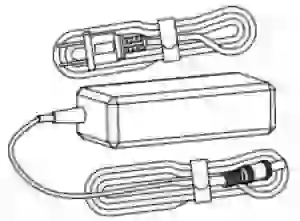
- 12V AC adapter
- Allen key
- Mouse
- Keyboard
- Installation disk

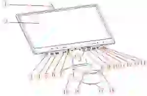
Chapter 4 Introduction to Camera Body
Introduction to camera body
- WiFi antenna: external signal antenna can enhance WiFi signal transmission
- 15.6″ LCD screen
- Speaker hole: volume channel hole
- USB3.0 interface:Can connect a mouse, keyboard or USB flash disk, convenient use of embedded APP
- USB2.0 interface: Can connect a mouse, keyboard or USB flash disk, convenient use of embedded APP
- HDMI interface: Through the HDMI cable, connect with the display device with HDMI interface, realize video, signal transmission
- Rotation axis: Support the display front and back , up and down rotation
- Power interface: for power supply.
- Network port: connect to the camera and power the camera.
- USB2.0 interface: Can connect a mouse, keyboard or USB flash disk, convenient use of embedded APP.
- Headset interface: Connect with the headset wire to realize the mutual transmission of audio signals.
- Reset hole: Long press for 8 seconds to reset the camera.
- LED indicator light: there are two colors of lights
- startup state: the green light flashes when starting up until entering the system. After entering the system, the green light is always on when there is no WiFi connection.
- WiFi: flash green light.
- Power off switch
- Turn on:Long press for 3 seconds
- Turn off:Long press for 3 seconds
- Focusing screw: screw the adjusting screw to adjust the focal length of the microscope.
- Master interface: connect with the eyepiece end of the biological microscope.
- Public interface: connect with the objective end of the biological microscope.
- Tightening screws: tighten screws with allen key to fix the eyepiece of the biological microscope.
Chapter 5 Product Installation
Install with a binocular microscope
- Separate the objective end of the microscope from the eyepiece end, as shown in figure
- loosen the fixing screw of the microscope;
- take out the eyepiece end of the microscope.
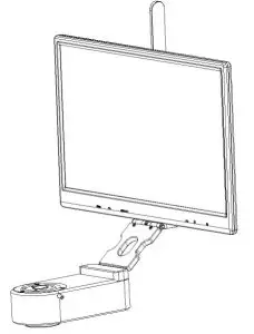
- Installation to binocular biological microscope
- place the smart all-in-one camera to the end of the microscope objective, as shown in figure 2;
- tighten the fastening screw at the microscope objective end and fix the smart all-in-one camera on the microscope.
- Microscope eyepiece end installation, as shown in figure 3:
- the microscope eyepiece end is inserted into the master interface end of smart all-in-one camera
- tighten the fastening screws of the smart all-in-one camera; and fix the eyepiece end of the microscope on the smart all-in-one camera;Figure 1Figure 2Figure 3
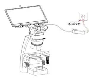
- The adapter interface is inserted into the display power hole. Connect the adapter to 110-240V AC.
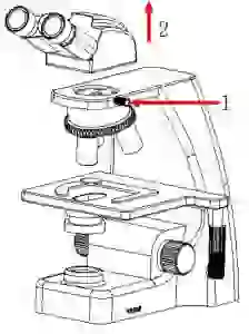 Figure 2
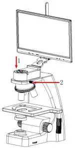 Figure 3
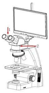
Uninstallation with a binocular microscope
- Reverse the installation order
Chapter 6 Instructions for Use
Software installation
- Install the KoPa Capture software, put the attached CD into the DVD drive of the computer, click the KoPa Capture Install file, and install the software according to the prompts. Refer to[ User Manual of KoPa Capture ] for the specific installation steps.
- Install android APP with CD (for android system mobile devices only)
- Use a mobile device (tablet or cell phone) to scan the QR code of the side of camera to download and install APP according to the prompts. Select the APP download entrance according to the system type of the mobile device.


- Android users who can log into the Google app store can click one of the two buttons
- to download.
- For android users in mainland China, click to download
- For iOS users, please click to download.
After downloading the APP, press the prompt to allow installation and allow all authorization. If you click “not allow”, you will be unable to connect normally.
Camera connection
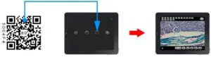
WiFi connectionMethod 1: Automatic connection to mobile devices via scan QR code
- Mount the camera to the microscope: refer to “Chapter 5”,
- Power the camera
- Run “KoPa WiFi Lab”APP,
- Click the “scan” icon in the App and scan the WiFi QR code on the top of camera to preview image,
- Please refer to [ User Manual of KoPa WiFi Lab ] for detailed operation
Method 2: Manually connect to mobile devices by entering a password
- mounting the camera to a microscope: refer to “Chapter 5”
- power the camera
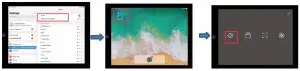
- search for the following WiFi signal in the Settings of the mobile device and enter the passwordWiFi name: WiFiCamera_5G_xxxxxx;Default Password: 12345678
- Run “KoPa WiFi Lab” APP and click the preview icon of the APP to display image.
- Please refer to [ User Manual of KoPa WiFi Lab ] for detailed operation.
HDMI connection
- mounting the camera to a microscope: refer to “Chapter 5”
- connect the camera with the display device with HDMI cable, and turn on the HDMI display device.
- power the camera
- Plug a mouse to the USB port.
- Long press the power switch on the camera for 3 seconds to activate the camera
- The camera is started normally. Please refer to the [User Manual of KoPa WiFi Lab AO] for detailed operation.
Parfocal
- Place the specimen on the loading platform of the microscope, adjust the eyepiece diopter to the minimum value, and use the 10X objective lens. It is recommended to use any black spot/or the darkest point on the focusing section under visual observation to be the clearest.
- Use the allen key to turn the focusing screw and adjust the focal length until the image from software is clear.
Start to useThe camera is ready for use now
Chapter 7 Disclaimer
- In order to protect the legitimate rights and interests of users, please carefully read the instructions, disclaimers and safety instructions provided with this product before using it. The company reserves the right to update the above documents. Please operate the product according to the instructions and safety instructions.
- Once you begin to use the product, you shall be deemed to have read, understood, recognized and accepted all terms and contents of the product’s instructions, disclaimers and safety instructions. Users undertake to be responsible for their actions and all consequences. User undertakes to use the product only for legitimate purposes and agrees to these terms and any relevant policies or guidelines that the company may establish.
- In the process of using this product, please strictly abide by and execute the requirements including but not limited to the instructions and safety instructions. All personal injuries, accidents, property losses, legal disputes and other adverse events that cause conflicts of interest caused by violation of the safety instructions or irresistible factors shall be borne by users themselves, and the company shall not assume any responsibility.
- Safety instructions:
- please do not use wet hands to plug and unplug the power supply of the equipment.
- please be sure to use a regular brand power socket, and make sure the grounding is well grounded to prevent electric shock.
- please be sure to make regular safety checks on sockets and plugs to avoid potential electrical safety hazards caused by aging and short circuit.
- please be sure not to use the product in a humid or hot environment to ensure the safety of the product.
- please be sure to loosen bundle cords of the power cable before using, to avoid electromagnetic induction and heating, thus increasing the heat dissipation speed.
- please be sure not to use the product equipment or socket or other places in high or easy to fall, so as to avoid damage.
- before opening the socket power supply, please be sure to turn off the load power switch of the product equipment.
- the company reserves the rights to improve product, upgrade technology and change parameters without prior notice.
FCC Warning:
This equipment has been tested and found to comply with the limits for a Class B digital device, pursuant to part 15 of the FCC Rules. These limits are designed to provide reasonable protection against harmful interference in a residential installation. This equipment generates, uses and can radiate radio frequency energy and, if not installed and used in accordance with the instructions, may cause harmful interference to radio communications. However, there is no guarantee that interference will not occur in a particular installation. If this equipment does cause harmful interference to radio or television reception, which can be determined by turning the equipment off and on, the user is encouraged to try to correct the interference by one or more of the following measures:
- Reorient or relocate the receiving antenna.
- Increase the separation between the equipment and receiver.
- Connect the equipment into an outlet on a circuit different from that to which the receiver is connected.
- Consult the dealer or an experienced radio/TV technician for help.Caution: Any changes or modifications to this device not explicitly approved by manufacturer could void your authority to operate this equipment.
 report this ad
This device complies with part 15 of the FCC Rules. Operation is subject to the following two conditions:
- This device may not cause harmful interference, and
- this device must accept any interference received, including interference that may cause undesired operation.This equipment complies with FCC radiation exposure limits set forth for an uncontrolled environment. This equipment should be installed and operated with minimum distance 20cm between the radiator and your body
[xyz-ips snippet=”download-snippet”]