
![]() KubergLight KitAccessory for KUBERG Rangerand Ranger Double batteryOWNER’S MANUAL
KubergLight KitAccessory for KUBERG Rangerand Ranger Double batteryOWNER’S MANUAL
Introduction
This manual describes the assembly process for the new KUBERG Light kit. For additional information regarding the light kit, please read the Ranger manual thoroughly. You can view and download it at www.kuberg.com/owners-manual.The assembly requires further skills, so we highly recommend it to be completed by your local service dealer.
Important symbols and terms
This Owner’s Manual uses the following symbols and terms to call your attention to Warnings, Cautions, and Notes:![]() WARNING!A Warning indicates a potentially hazardous situation, which if not avoided, could result in bodily injury or death, in addition to the damage to property. Read the text accompanying the warning to be aware of the specific hazard.
WARNING!A Warning indicates a potentially hazardous situation, which if not avoided, could result in bodily injury or death, in addition to the damage to property. Read the text accompanying the warning to be aware of the specific hazard.![]() CAUTION!A Caution indicates a potentially hazardous situation, which if not avoided, may result in damage to equipment or an inadvertent system failure. Read the text accompanying the Caution to be aware of the specific hazard and to avoid damage or system failure.
CAUTION!A Caution indicates a potentially hazardous situation, which if not avoided, may result in damage to equipment or an inadvertent system failure. Read the text accompanying the Caution to be aware of the specific hazard and to avoid damage or system failure.![]() NOTE:The text accompanying a Note provides helpful or other important related information.
NOTE:The text accompanying a Note provides helpful or other important related information.
Light kit assembly
- Be sure the magnetic kill switch is in the OFF position.
- Using Allen wrench #3 loosen and remove 3 bolts from the left frame cover (above the battery) and put the cover aside.

- With the same wrench loosen and remove 2 bolts from the inspection lid, uncover the controller from the bottom side, and using Allen wrench #4 loosen the upper controller bolt.
- Using Allen wrench #4 loosen and remove 2 bolts from the front number plate holder and remove it.
- With the same wrench loosen and remove 1 bolt holding the front fender, cut 2 zip ties, and remove the fender from the front fork.
- Take Allen wrench #3 and remove the bolt from the back of the rear fender.
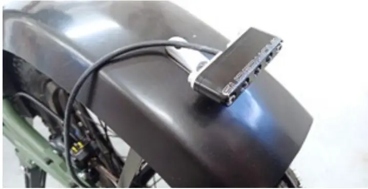
- Install the tail light and screw in the bolt removed during the previous step into the lower hole of the tail light holder and into the rear fender reinforcement. Do not tighten it yet.
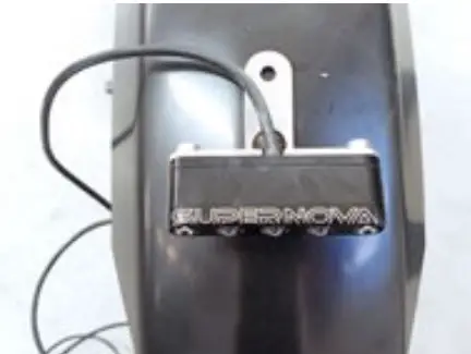
- Align the tail light in parallel with the side of the rear fender. The light must shine backward, not slantwise.
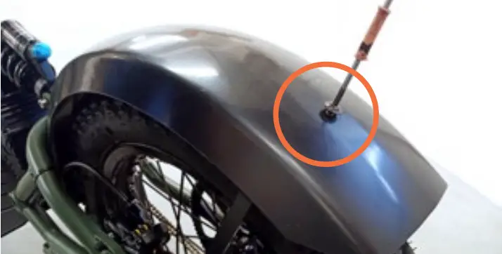
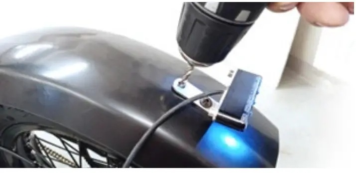
- According to the picture, make a hole into the rear fender using a 5mm drill and a gentle force (the fender is plastic). Be highly aware of the rear tire and avoid any contact between the drill and the rear tire. To be absolutely sure you won’t make a contact with the rear tire, you can cover it with a piece of sheet metal, or you can remove the rear wheel. The instructions on how to remove and reinstall the rear wheel can be found in the main Ranger manual on page 23. The manual is available for view and download at www.kuberg.com/owners-manual.
- Unscrew the bolt from the tail light, installed in step #7.
- Gently pull the rear fender up with one hand by approx. 2,5cm (1”), attach the tail light and insert the supplied bolt into the upper hole. Use the supplied washer and the locking nut from the bottom side of the rear fender.
- Align the lower hole of the tail light holder with the lower hole in the fender and with the thread in the fender reinforcement at the same time. Insert the bolt, removed during step #10.
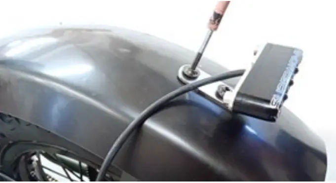
- Secure the tail light to the fender with Allen wrench #3 and Spanner #8 (4-6Nm on both bolts).
- Run the cable along with the rear fender reinforcement, below the rear brake caliper and along the upper and front tube on the left side of the rear swingarm. Use supplied zip ties according to the picture. You can remove the original zip ties holding the brake hose to the swing arm but avoid the tail light cable and brake hose to make any contact with the rear brake disc or rear tire!
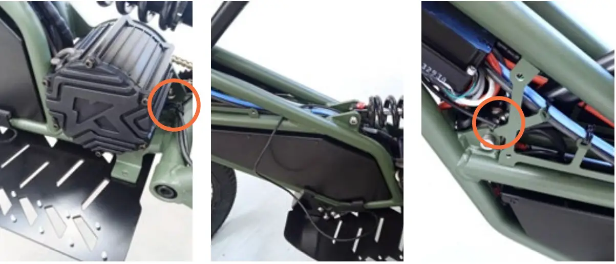
- Run the cable under the motor and above the battery, along with the main motor cables. Use supplied zip ties to fasten the tail light cable to the frame.
- Thread the cable connector through the rubbered eye on the left upper side of the frame. You can use pliers (not supplied) but be very careful not to damage the connector or the pins inside.
- Gently push the cable under the controller, according to the picture.
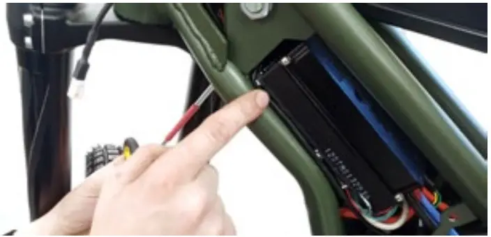
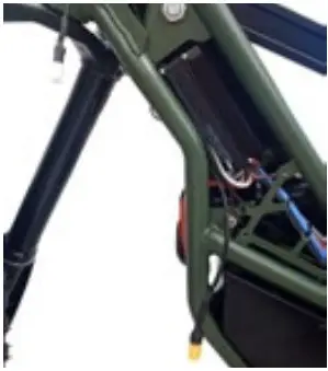
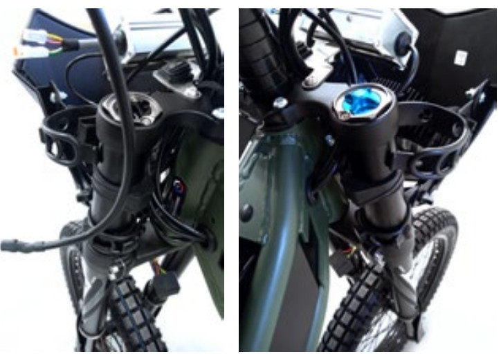
- Take the supplied short cable with the fuse and thread its red and black connectors from the inside of the frame up through the same rubbered eye as in step #16. Again, push the lower part of the cable with the yellow connector under the controller.
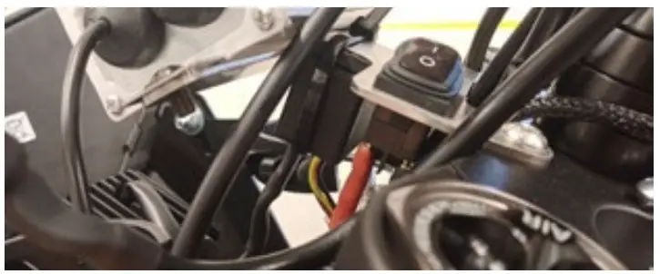
- Connect the yellow connector to the corresponding connector on the controller, temporarily covered by the shrink tube.
- Make sure the main light switch on the voltage converter holder is in the OFF position.
- Connect the upper connectors from the short cable to the switch on the voltage converter – red beside red and black beside black.
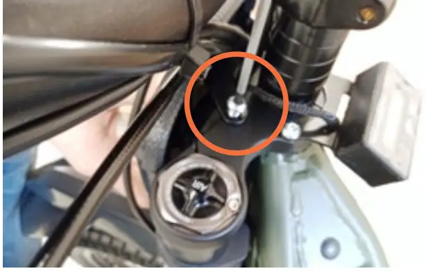
- Use Allen wrench #4 and 2 bolts removed during step #3 and tighten the voltage converter to the fork upper plate.
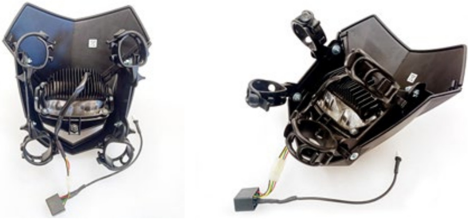
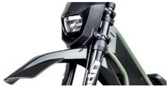
- Take the headlight from the big plastic bag and assemble it according to the picture.
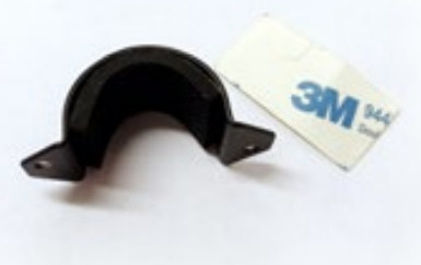
- Use the supplied 3M rubber tape and stick it to the inner side of the lower holder for the high/low beam switch.
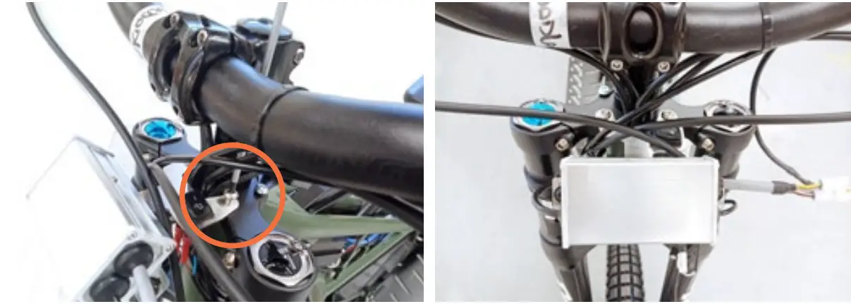
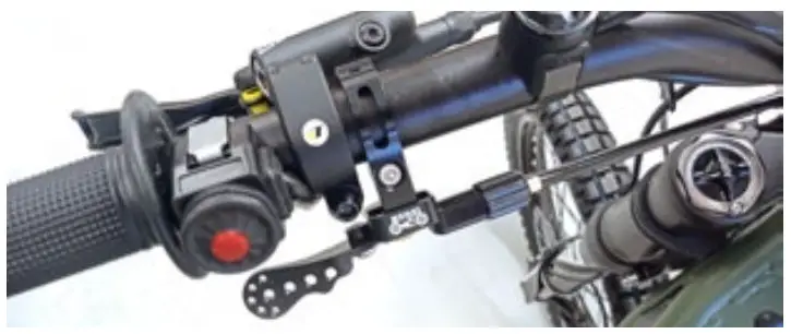
- Move the kill switch on the handlebar to the right to create a space for the high/low beam switch.
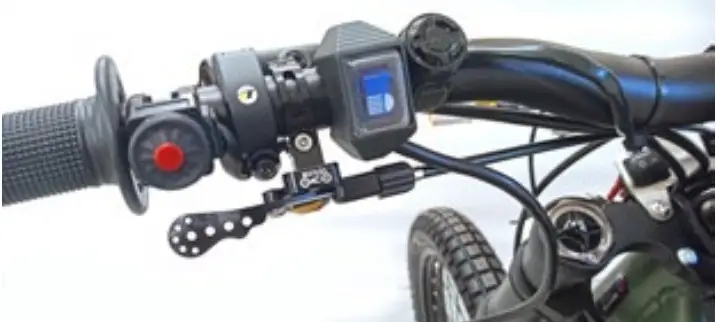
- Using a cross screwdriver (not supplied) to install the high/low beam switch on the left side of the handlebar, according to the picture.
- Install the headlight onto the front fork just by using the 2 lower rubber belts. Leave the upper rubber belts detached for better access during the rest of the light kit installation.
- Connect the white connector from the high/low beam switch on the handlebar to the corresponding white connector on the voltage converter.
- Use the supplied small zip tie and secure the fuse (black box) onto the lower side of the voltage converter holder.
- Secure the 2 upper rubber belts of the headlight onto the front fork.
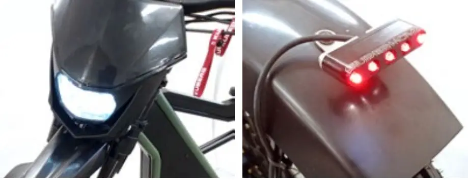
- Start the motorcycle by putting the kill switch in the ON position, but the main light switch in the ON position and check the front and the rear light function and also the function of the high/low beam switch.
- If both lights don’t light up, double-check the whole installation steps 1-30. If everything works fine, but the kill switch is in the OFF position.
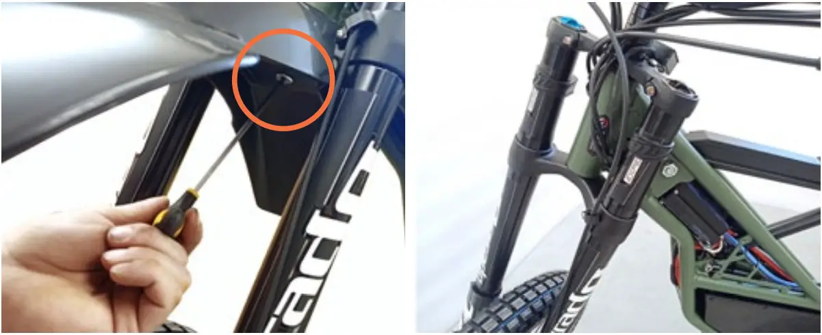
- Install the front fender back to its place, tighten its bolt using Allen wrench #4, and secure the front fender position with supplied zip ties.
- With the same wrench tighten the upper controller bolt.
- Put the inspection lid back in its place and with Allen wrench #3 install and tighten 2 bolts holding the inspection lid on the frame.
- Reinstall the left frame cover using 3 bolts removed in step #2 and with Allen wrench #3.
- Check all bolts for tightness and cut unnecessary ends of all used zip ties. Be extra careful not to cut any cable or brake hose!
- Find a level surface with at least 12m (39ft) of free space and a blank wall of one color.
- Using a duck tape with good visibility, mark the height of 85 cm (2ft 9”) above ground.
- Dim the room lighting (or wait till nightfall), sit on the motorcycle, and point the front light vertically onto this wall.
- Reverse the motorcycle perpendicular from the wall to the point when the center of the front wheel will be distant 10m (32ft 9”) from the wall.
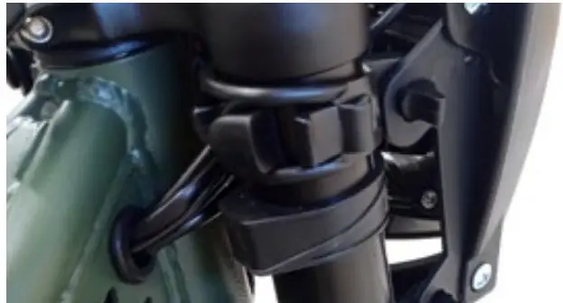
- Using the adjusting bolt under the front light (visible from the front) set the upper edge of the light cone on the wall to touch the duck tape. Check the light cone on the wall while sitting on the motorcycle, because your weight and the front and the rear suspension settings may greatly influence the light. Do the suspension settings of your Ranger prior to this step.


![]() WARNING!Do not ride at night or under low visibility conditions, if your KUBERG Ranger is NOT equipped with the light kit.
WARNING!Do not ride at night or under low visibility conditions, if your KUBERG Ranger is NOT equipped with the light kit.
![]()
KUBERG s.r.o.Zengrova 630/83Ostrava – Vítkovice, 703 00Czech Republicemail: [email protected]www.kuberg.com
References
[xyz-ips snippet=”download-snippet”]