
![]() www.kucht.comINSTALLATION GUIDE AND USER MANUALUNDER CABINET RANGE HOODAPPLICABLE MODEL: KRH301A, KRH361A, KRH481A, KRH3020A, KRH3620A, KRH4820A
www.kucht.comINSTALLATION GUIDE AND USER MANUALUNDER CABINET RANGE HOODAPPLICABLE MODEL: KRH301A, KRH361A, KRH481A, KRH3020A, KRH3620A, KRH4820A
BE A PRO IN YOUR KITCHEN
![]()
WELCOME TO THE KUCHT FAMILY
IMPORTANT: Read and save these instructions.NOTICE: Installer: Leave this guide with the homeowner. Homeowner: Keep this guide for future reference.WARRANTYKUCHT Warranty covers defects in Parts and Labor for functional parts that are the result of normal usage for a period of time of 4 Years for Parts and Labor from the date of purchase. Functional parts are those components parts that are critical to the performance of the product’s essential function. Nonfunctional parts are those that are not critical like knobs, handles, or cosmetic parts. KUCHT will repair or replace the unit or any parts, therefore, as required, subject to these terms and conditions.General Conditions:a. Warranty does not cover failure as a result of misuse, abuse, rust or corrosion, spilled liquids or foreign objects found inside the unit; repair of damage caused by accident, theft, fire, flood, external causes such as, but not limited to, blow fuses, inadequate electrical power, water and gas lines beyond the equipment, or any use of the product not authorized by the manufacturer.b. The maximum liability of the warranty for product replacement or repair shall not exceed the original purchase price of the product.c. KUCHT reserves the right to repair or replace the covered product with a comparable feature model of like kind.d. Warranty does not cover deterioration of the appearance of the product, any cosmetic part such as paint, porcelain, glass, dents, scratches, chips, rust or peeling.e. Any damage resulting from unauthorized replacement parts, improper service, or modifications made to the covered product are not covered.f. KUCHT is released from all liability due to indirect, consequential, or incidental damages.Limit of Liability:Our Liability is limited to the original price of the covered equipment

IMPORTANT SAFETY INSTRUCTIONS
WARNING: TO REDUCE THE RISK OF FIRE, ELECTRIC SHOCK, OR INJURY TO PERSONS, READ THE FOLLOWING:Use this unit only un the manner intended by the manufacturer. If you have questions, please contact the manufacturer.Before servicing or cleaning the unit, switch the power off and lock the service panel. This will prevent the power from accidentally turning on. If the service panel does not lock, secure a warning label, such as a tag, to the service panel.Installation work and electrical wiring must be done by a qualified professional(s) in accordance with all applicable codes, standards, and fire-rated constructions.Do not operate any fans with a damaged cord or plug. Discard the fn or return it to an autorized service facility for further examination and/or repair.To prevent backdraft, sufficient air is needed for proper combustion. Gas from fuel-burning equipment needs to exhaust through the flue (chimney). Follow the heating equipment manufacturer´s guidelines and safety standards such a those published by the National Fire Protection Association (NFPA), the American Society for Heating, Refrigeration and Air Conditioning Engineers (ASHRAE), and the local code authorities.When cutting or drilling into walls or ceilings; be aware of electrical wires, piping, and other utilities.Ducted fans must always be vented outdoors.
CAUTION: For general ventilation use only. Do not use to exhaust hazardous or explosive materials and vapors.CAUTION: To reduce the risk of fire and to properly exhaust air, be sure to duct air outside. – DO NOT vent exhaust air into attics, crawl spaces, garages, or within walls and ceilings.
WARNING: TO REDUCE THE RISK OF A RANGE TOP GREASE FIRE, READ THE FOLLOWING:Never leave surface units unattended at high settings, Boil-over can cause smoke and grease to spill over that may ignite. Heat oils slowly on low or medium settings.Always turn the hood ON when cooking at high heat or when flam being food (i.e. Crepes Suzette, Cherries Jubilee, Peppercorn Beef Flambé).Use proper pan size. Always use cookware appropriate for the size of the surface element.WARNING: TO REDUCE THE RISK OF INJURY. IN THE EVENT OF A RANGE TOP GREASE FIRE, READ THE FOLLOWING:SMOTHER FLAMES with a close-fitting lid, cookie sheet, or metal tray, then turn off the burner. BE CAREFUL TO PREVENT BURNS. If the flames do not go out immediately, EVACUATE AND CALL THE FIRE DEPARTMENT.NEVER PICK UP A FLAMING PAN – you may get burnedDO NOT USE WATER, including wet dishcloths or towels – a violent steam explosion will result.Use a fire extinguisher ONLY if:– You know you have a Class ABC extinguisher, and you already know how to operate it.– The fire is small and contained in the area where ir started.– The are department is being called.– You can ght the are with your back to an exit.Based on “Kitchen Fire Safety Tips” published by NFPAWARNING: TO REDUCE THE RISK OF FIRE OR ELECTRICAL SHOCK, DO NO USE THIS FAN WITH ANY SOLID-STATE SPEED CONTROL DEVICE.
TO REDUCE THE RISK OF FIRE, ELECTRIC SHOCK, INJURY TO PERSONS, OBSERVE THE FOLLOWING:
- Use this unit only in the manner intended by the manufacturer. If you have questions, contact the manufacturer at the address or telephone number listed in the warranty.
- Before servicing or cleaning the unit, switch power off at the service panel and lock the service disconnecting means to prevent power from being switched on accidentally. When the service disconnecting means cannot be locked, securely fasten a prominent warning device, such as a tag, to the service panel.
- Installation work and electrical wiring must be done by a qualified person(s) in accordance with all applicable codes and standards, including fire-rated construction codes and standards.
- Sufficient air is needed for proper combustion and exhausting of gases through the flue (chimney) of fuel burning equipment to prevent back-drafting. Follow the heating equipment manufacturer’s guidelines and safety standards such as those published by the National Fire Protection Association (NFPA), and the American Society for Heating, Refrigeration and Air Conditioning Engineers (ASHRAE), and the local code authorities.
- When cutting or drilling into wall or ceiling, do not damage electrical wiring and other hidden utilities.
- Ducted fans must always be vented to the outdoors.
- Acceptable for use over a tub or shower when connected to a GFCI (Ground Fault Circuit Interrupter) – protected branch circuit (ceiling installation only).
- This unit must be grounded.
CAUTION
- For general ventilating use only. Do not use to exhaust hazardous or explosive materials and vapors.
- This product can be installed in a wall if mounted 8-ft. or more above the floor.
- To avoid motor bearing damage and noisy and/or unbalanced impellers, keep drywall spray, construction dust, etc. off the power unit.
- Please read the specification label on the product for further information and requirements.
TOOLS & PARTS REQUIRED FOR INSTALLATION
Electrical drill or ratchet driver1/2″ drill bit for drilling pilot holes1 1/4″ drill bit for drilling electrical wiring access hole Screwdriver: Phillips & Straight bladePliersTape Measure or ruler + pencilElectrical supplies for wiringAluminum foil tape and/or HVAC tapeHammerJigsaw or saber sawStud finder
CONTENT OF THE BOX
Body (Main Unit): 1 pcInstallation Manual: 1 pcMetal Grease Filter: 1-4 pcsHardware: 1 set
LOCATION REQUIREMENTS
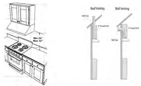
Observe all governing codes and local ordinances. Have a qualified technician install the range hood. It is the installer´s responsibility to comply with installation clearances specified on the model serial rating plate. The canopy hood´s location should be away from strong draft areas, such as windows, doors, and strong heating vents. Recommended heights are shown. Given dimensions provide minimum clearance.
VENTILATION REQUIREMENTS
Range hoods must be ventilated to the outdoors, except for non-vented (recirculating) installations.Do not ventilate the range hood into an article or other enclosed areas.Do not use 4″ (10.2 cm) laundry-type wall caps. The length of the range hood exhaust and the number of elbows should be kept to a minimum to provide maximum performance.Use no more than three 90° elbows. Make sure there is a minimum of 24″ (61 cm) of straight duct between the elbows if more than one elbow is used.Do not install two elbows together. Use clamps to seal all joints in the vent system.The vent system must have a damper. If the roof or wall cap has a damper, do not use the damper supplied with the range hood.Use caulking to seal exterior walls or roof openings around the cap.The size of the vents should be uniformMAKEUP AIRLocal building codes may require the use of makeup air systems when using ventilation systems greater than specified CFM of air movements in your area.COLD WEATHER INSTALLATIONSAn additional back draft damper should be installed to minimize backward cold airflow. A thermal break should be installed to minimize the conduction of outside temperatures as part of the vent system. The damper should be on the cold air side of the thermal break. The break should be as close as possible to where the vent system enters the heated portion of the house.VENTING METHODThis canopy hood is factory set for through the roof wall. A 6″ (15.2 cm) round vent system is needed for installation. The hood exhaust opening is 6″ (15.2 cm ) round. To vent through a wall, a 90° elbow is needed. If the exhaust ducting with a diameter of less than 5.91″ (150 mm) or if flat ducting is used, the noise level of the range hood will increase and extraction will be less efficient.REAR DISCHARGEA 90° elbow may be installed immediately above the hood.
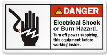
ELECTRICAL REQUIREMENTS & SPECIFICATIONSIMPORTANT: Observe all governing codes and ordinances.It is the customer’s responsibility to contact a qualified electrical installer.A 120 Volt, 60 Hz, AC-only, fused electrical supply is required on a 15-amp circuit.DO NOT have a fuse in the neutral or ground circuit.The 3-prong outlet should be grounded. If the power cord plug is not used, the power cord’s green wire should be connected to the ground.Check with a qualified electrician if you are not sure that the range hood is properly grounded.DO NOT ground to a gas pipe. The range hood must be connected with copper wire/plug only.The range hood should be connected directly to the fused disconnect (or circuit breaker) box through a flexible armored or non-metallic sheathed copper cable.ETL listed strain relief must be provided at each end of the power supply cable.
| ITEM | Unit | Parameter |
| Rated Voltage | V | 110 |
| Rated Frequency | Hz | 50 |
| Motor Power | W | 50 |
| Lamp Power | W | ≤2×1.5 |
| Air Pressure | Pa | >160 |
| Noise Level | dB(A) | <67 |
| Air Output Diameter | mm | 150 |
ATTENTION HOMEOWNERThese installation steps are meant to be a general guideline for mounting and installing yours under cabinet range hood. If you require assistance, please contact your local contractor. Please exercise extreme caution when handling a range hood to prevent the risk of injury and electric shock. Building codes will vary. It is the buyer or contractor’s responsibility to know the local county or state regulations before the installation of this range hood.
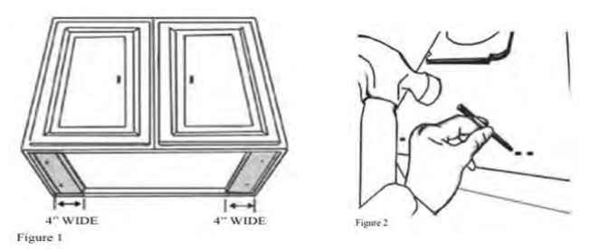
PREPARATIONS:NOTE: To avoid damage to your hood, prevent debris from entering the vent opening Decide the location of the venting pipe from the hood to the outside. Please see the “Venting Method” section. A straight, short vent will allow the hood to perform more efficiently. Try to avoid as many transitions, elbows, and long-run as possible. This may reduce the performance of the hood.IMPORTANT: Peel white or blue plastic protective film off the hood. Use HVAC foil tape/duct tape to seal joints between the pipe sections. For installing under cabinets with a recessed bottom, attach 4-inch wide wood filler strips (not provided) on each side. Refer to Figure 1. Using references in measurements and diagrams provided, create an opening for electrical wires and hood exhaust under the cabinetCAUTION: If moving the cooking range is necessary to install the hood, first turn off the power. Always turn off the gas before moving a gas range. Puncture the knockout holes (for mounting under the cabinet) on the hood as shown in Figure 2. If necessary, attach two rubber panels with adhesive tape to the rear corners of the range hood. This will help reduce vibrations and shaking when in operation.
ATTENTION HOMEOWNER
Two people will be required to lift and install the main unit. We highly recommend professional help and an extra set of hands. Measure the distance between the stovetop and the bottom of the range hood. A distance of 24″ to 32″ is recommended. There are two methods (A or B) to mount the range hood, choose the one that better fits your setup and model.
STEP 1 | METHOD A
Proceed if you would like to mount this range hood without using the hood mounting bracket.
- Using references in the Location Requirements section, center the hood beneath the cabinet and flush with the front of the cabinet.
- Draw the electrical wires through the cabinet access opening if not done so already.
- From inside of the hood, place screws into the exact center of each knockout hole and secure to cabinet bottom. Finish tightening all screws until secure. Be careful when using electrical screwdrivers, they may cause damage to the range hood.Skip Method B below and proceed to step 2.CAUTION: Make certain the range hood is fully secured before releasing!
STEP 1 | METHOD B
Proceed if you would like to mount this range hood using the provided hood mounting bracket (If included).
- Using references in the Location Requirements section, mark the leveling point of the hood. Position two mounting screws on the wall, leaving 1/8″ space away from the wall. Mounting the hood on wall studs is highly recommended.
- Attach the hood mounting bracket to the back of the hood with four screws as shown in Figure 3.
- Puncture the knockout wire access hole at the back of the hood and draw the electrical wires.
- Align hood-mounting brackets to the screws on the wall and hook the hood into place as shown on the next page.
- Tighten screws to secure hood to the wall.CAUTION: Make certain the range hood is fully secured before releasing!
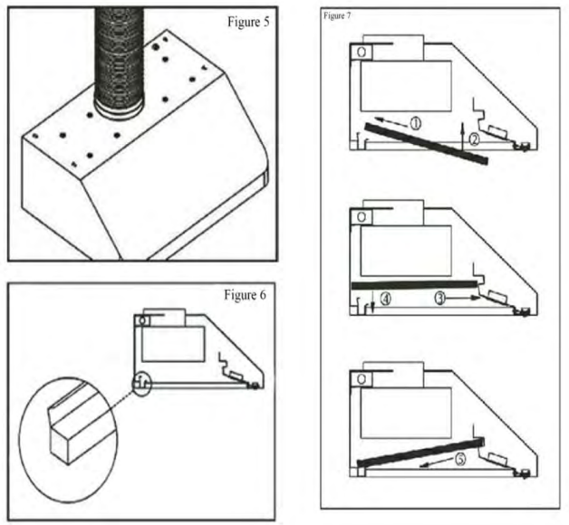
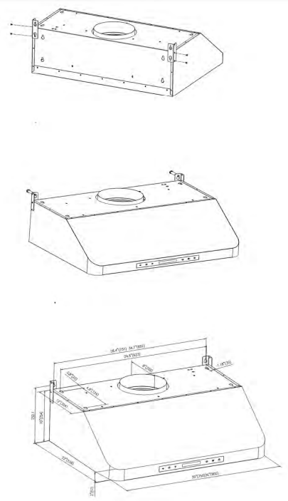 STEP 2For safety purposes, pre-drilled mounting holes are provided through the back of the hood. For a more secure installation, use as many mounting holes as needed to secure the unit from the inside of the hood.STEP 3Use a 8″ diameter (size may vary) venting pipe (follow building codes in your area) to connect the exhaust on the hood to the ductwork above. Use HVAC foil tape/duct tape to make all joints secure and air-tight.SAFETY WARNING: Risk of electrical shock. This range hood must be properly grounded. Make sure this is done by a qualified electrician in accordance with all applicable national and local electrical codes. Before connecting wires, switch power off to prevent power from being switched on accidentally.STEP 4Connect the range hood to a designated standard outlet or cut off the plug and connect three wires (black, white and green) to house wires and cap with wire connectors. Connect according to colors (i.e. black to black, white to white, and green to green.) (If applicable).STEP 5Store excess wires in the wiring box.STEP 6Place oil tray into recess support near the rear of the hood. Refer to Figure 6.STEP 7To install baffle filters, refer to Figure 7 for placement.
- Angle baffle filter toward the back of the hood.
- Push baffle filter up until almost leveled.
- Slide forward into a recess behind the front of the hood.
- Lower the baffle filter.
- Slide back until it fits into resting position.
STEP 8Turn power ON with Control Panel. Check all lights and fan operationMake sure to leave this installation guide for the homeowner if you are a contractor.
CONTROL PANEL LAYOUT AND BUTTONS SETTINGSA) REMOTE CONTROL: Same function as “power” buttonB) CLOCK / DELAY SETTING: When the fan is running, press the time delay button, the time delay button will blink, press + or the system will automatically shut down after 1 – 15 minutes. press + or – to choose the time delay or exit function.C) LAMP: Press the lamp icon one time to activate the light, press it again to turn the light off.D) “-“: In standby mode, press this button one time, the range hood will start at F1 speed, if this button is pressed again, the speed will remain the same.E) “+”: In standby mode, press this button one time, the range hood, will start at F4 spread, if this button is pressed again, the speed will remain the same.F) POWER: Turns on the hood / set it to standby mode and show the time.
HOW TO ADJUST THE TIME CLOCK OR SET THE TIME
- Press the clock (B) Button
- Change Hour time using “+” and “-” buttons
- Press the clock (B) Button again
- Change Minute time using “+” and “-” buttons
- Press the clock (B) Button again to finish
SUPPORT AND SERVICE
This range hood comes with full unlimited lifetime support.This means that if you come across any problem after the warranty has expired, a qualified Kucht member will assist you or your trusted technician using video chat in any repair process. You will also have access to repair videos, tutorials, manuals, and any extra help that is available.
TO ARRANGE FOR SERVICE
Prior approval from Customer Service is required prior to start the service.To initiate a service claim please submit a ticket at www.kucht.com or contact KUCHT for assistance on how to initiate a service claim. Please have your original bill of sale and Serial Number of the unit available to our customer service representative is able to quickly arrange for service.
STYLE AND SIMPLICITY™
 report this ad
![]()
![]() WE TRANSFORM A SIMPLE KITCHEN INTO A PRO ONE. THIS IS WHY WE CARE ABOUT MAKING VERY HIGH-PERFORMANCE RANGES AND HOODS, TO MAKE YOU FEEL LIKE A PRO AND STYLISH COOKER.
WE TRANSFORM A SIMPLE KITCHEN INTO A PRO ONE. THIS IS WHY WE CARE ABOUT MAKING VERY HIGH-PERFORMANCE RANGES AND HOODS, TO MAKE YOU FEEL LIKE A PRO AND STYLISH COOKER.
DESIGN: LONDON DC – WWW.LONDON-DC.COMFOR MORE DETAILS AND INFORMATION, PLEASE VISIT OUR WEBSITE WWW.KUCHT.COM
References
[xyz-ips snippet=”download-snippet”]