![]()
KymetaTM u8 Satellite TerminalQuick Start GuidePRODUCT CODE: U8901-10113-0Document number: 700-00197-000 rev A10 August 2021
Introduction
This document contains important step-by-step details for the installation and setup of the KymetaTM u8 satellite terminal (U8901-10113-0). The Kymeta u8 satellite terminal has all the performance of the u8 antenna with an embedded iQ 200 without the multi-WAN.For information on the Kymeta u8 antenna web-based user interface, refer to the 700-00139-000 KymetaTM u8 antenna software user guide.The u8 satellite terminal includes a QR code on the antenna communications module, under the side access panel, next to the LED status panel to show the as-built configuration of the system. The following is an example of the information included in the QR code:PRODUCT NAME: KYMETA U8 SAT TERMINAL, 20WPRODUCT_CODE: U8901-10112-0PRODUCT_SN: ABQ000K200624006ANTENNA SN: ABP511K200710025MODEM SN: 017806HD1 SN: N/AHD1 IMEI: N/AIP ADDRESS: 192.168.44.2SIM ID: N/AThe footprint of the u8 terminal is 89.5 cm × 89.5 cm × 14 cm (35.2 in. × 35.2 in. × 5.5 in.). Ensure you have enough mounting space. Figure 1. u8 satellite terminal dimensionsThe u8 satellite terminal comes with two Ethernet jumper cables that extend the Ethernet connection outside of the shroud. For more information on u8 cabling and the u8 products cable extension kit, see Appendix A. u8 satellite terminal cabling diagram.
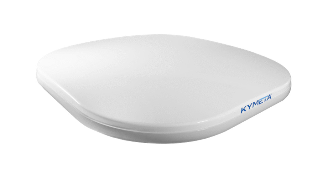
 Figure 2. u8 satellite terminal external guide
Product considerations
2.1 General considerations
- For your safety, read the 700-00122-000 KymetaTM u8 products safety and handling guide before beginning installation.
- Acquire all the hardware and tools required for u8 terminal installation; they aren’t provided with the product.
- Use the corner handles to lift the u8. Never grab or lift the u8 by the shroud, diplexer, or any other part of the RF chain. Never use the diplexer or any part of the RF chain to mount the u8 as they are not a structural part of the u8 and may be damaged if handled improperly. Avoid damaging the coating on the diplexer.
- u8 terminals operating under Kymeta FCC blanket authorization (call sign: E170070) must limit BUC output power to 42.3 dBm to maintain compliance with RF safety labeling on the unit ensuring general public safety during transmit operations. To limit the BUC output power, in the u8 web-based user interface, go to Pointing > Commissioning Mode page, and select the right Power Spectral Density (PSD) table. Limiting BUC output power and mounting above the human users or appropriately marking a keep-out area ensures safe exposure limits for all users.
- Use Mozilla Firefox to access the Kymeta web-based user interface (UI).
- The u8 is configured by default to use a DC power source and requires a 12 VDC to 36 VDC power source. To use an AC power source for the u8, purchase the AC-to-DC converter kit (U8ACC-00044-0).
- LAND-MOBILE: For the safety of your vehicle and rack system, obey all posted speed limits and traffic cautions. Adapt your speed to the conditions of the road and the load being carried.3
Unbox the u8 terminal
- Clear a flat surface and place a piece of foam, fabric, or non-abrasive material on the clean flat surface to prevent marks or damage to the face of the u8 antenna.
- Unpack the terminal. To open the box, lay it flat on an open area where it’s easy for one person to stand on each side near the clean assembly surface.
- With two people (one person on each side), lift the u8 out of the case, keeping the terminal parallel to the floor, and lay the antenna face down on the clean flat surface. Place a piece of foam, fabric, or non-abrasive material on the clean flat surface to prevent marks or damage to the face of the antenna.
![]() The u8 terminal box includes a large gray grey foam piece to protect the top of the u8 during transportation. Use this as a protective pad when working on the u8.
The u8 terminal box includes a large gray grey foam piece to protect the top of the u8 during transportation. Use this as a protective pad when working on the u8.
Plugin the terminal
![]() The Kymeta u8 terminal operates on 12 VDC to 36 VDC maximum. Exceeding 36 VDC may cause damage tothe equipment and is not covered under warranty.The u8 terminal is configured by default to use a DC power source.
The Kymeta u8 terminal operates on 12 VDC to 36 VDC maximum. Exceeding 36 VDC may cause damage tothe equipment and is not covered under warranty.The u8 terminal is configured by default to use a DC power source.
- If you are going to use the DC power source, proceed to 4.2 Power on the u8 terminal.
- If you are going to use an AC power source for the u8 terminal, install the AC-to-DC converter kit (U8ACC-000440) as described in 4.1 Install the AC-to-DC power kit.
4.1 Install the AC-to-DC power kitBefore installing the unit, you can open and remove the shroud without affecting the warranty or IP rating.4.1.1 Open the u8 shroud
- Place Kymeta u8 terminal shroud-up on a soft surface to protect the radome.
- Remove the (×8) M6 fasteners on the shroud using the T20 Torx driver. The cable glands on either side ofthe fan panel are not fixed to the shroud and must be removed to modify power cable routing.
- Gently lift the shroud until the fan cable connector is accessible. Disconnect the section attached to the fans and fan panel by unlocking the outdoor-rated Ethernet connector and gently pulling it to release. Then, fully remove the shroud and place it aside. Removing the fan panel from the shroud is not necessary.
- Access the power cable connector to install an AC-to-DC power kit.
4.1.2 Connect the AC-to-DC power kitConnect the AC-to-DC converter kit (U8ACC-00044-0) as described in the supporting instructions.4.1.3 Close the shroudReconnect the fan cable, and then set the shroud back and ensure the cable glands are properly secured. Pay special attention to the seating of the shroud, and the location of the cables beneath it. Ensure that the RF, power, and fan connector cables are clear of the 4 mounting points. Re-install the (×8) M6 fasteners and torque to 7.0 N-m (5.16 ft.lb.). These fasteners have a nylon patch so Loctite is not required. See also Appendix A. u8 satellite terminal cabling diagram.4.2 Power on the u8 terminal
- Ensure the u8 is in place with a view of the sky; see the guidelines in 6.3 Example installation sites.
- Connect all power cables.
- Power on the u8 terminal. You may hear the shroud fans power up and then reduce speed.
Connect
Connect to the u8 terminal administrative network:
- Open the access panel on the side of the terminal:a. Remove the (×2) Thumb Screws M6×12mm thumb screws.b. Slide the panel toward you to remove.
- Connect to the Ethernet 2 port.
- Set the static IP address of your administrative device to connect to the antenna IP address 192.168.44.2 (e.g., 192.168.44.30). Operation in motion with the access panel open or with an Ethernet 2 port connection is not recommended.
 Change your passwords after the first use. Leaving the passwords as the default is a security risk.
Physical access to the administrative network of the u8 is available by connecting to the Admin Ethernet port after opening the access panel on the side. You need to set the static IP address of your administrative device to connect to the antenna IP address 192.168.44.2 (e.g., 192.168.44.30). Operation in motion with the access panel open or with an administrative Ethernet connection is not recommended.5.1 Provision and commission the u8 terminal with KymetaTM Broadband servicesContact [email protected] to request a commissioning window. Provide your terminal serial number, contact name, and number, and requested commissioning window within the hours of 07:00-18:00 PT (UTC-8).Kymeta support will provision your terminal and provide you options files before the call, which you will load with Kymeta support during your commissioning window.Before commissioning, ensure your administrative laptop has access to the u8 administrative network, either with physical access under the access panel or wirelessly on the Admin Wi-Fi network. See Appendix C. Device login information for login information.During your commissioning window, ensure your terminal has a clear view of the sky, and then contact Kymeta support according to the instructions provided by the support team during the confirmation of your commissioning time. They will guide you through the process of connecting to the satellite for the first time.5.1.1 Provision and commission the u8 terminal without Kymeta™ Broadband servicesFor instructions refer to the 700-00139-000 KymetaTM u8 antenna software user guide, section “Software Commissioning Mode support”.You can access the u8 system for administration or monitoring. Full system status is available through the Kymeta Access application. To start using the Access portal, you need to configure the u8 terminal to connect to the internet/Intranet to make it possible for the Access app to connect to the antenna. This application also connects you to other system components for administration. Refer to Appendix C. Device login information for details.
Mount the u8 satellite terminal
6.1 Mounting considerations
- Prior to mounting, check that the terminal is grounded and the electrical power is disconnected from it.
- Practice basic electrical safety measures. Follow local, national, and other regulations with respect to these devices.
- During mounting, avoid obstructing the air intake screens or drain holes.
- Mount the u8 as far from the radar/transmitter as possible and outside of the radar beamwidth, typically ±15° elevation range, to avoid the u8 damage. Evaluate the performance of the u8 with all radar and transmitters operating normally before finalizing the mounting. Mount the u8 in an area above the accessible range of personnel within the operational range of the antenna to reduce the risk of RF exposure. Hazard zones can be set up on the antenna to prevent transmitting at specific angles relative to the antenna. Refer to 700-00139-000 KymetaTM u8 antenna software user guide, section “Set up hazard zones” for more information.
- Mount the u8 as far as possible from any equipment or materials that may cause magnetic interference for faster acquisition times.
- Satellite reacquisition is most efficient if you mount the terminal in direction of travel; refer to 8 Set up u8 antenna orientation for more details.
- Obstructing the direct path to the satellite degrades performance and may cause a loss of connection with the satellite. The antenna should have a clear line of sight: 15° 90° elevation (broadside to 75° scan angle), full 360° azimuth (broadside to 75° scan angle).
- Obstructing the face of the antenna degrades RF performance and could impair the GNSS capability of the antenna.
- The u8 has all cables routed out the rear side next to the fans. Ensure when mounting the u8 that this space isn’t blocked.
- The u8 terminal fans are critical to proper thermal function. When mounting the u8, keep at least a 305 mm (12 in.) open distance behind the fans and a minimum single exhaust zone vertically (up or down), horizontally (right or left), or some combination to minimize backpressure.
- The u8 terminal access panel on one side is removable for LED/admin Ethernet access. You need to ensure that this panel is reachable after you have mounted the u8.
- If you ordered any u8 accessory kit(s), refer to the installation instructions shipped with the kit(s).
6.2 Mounting solutions
- Kymeta offers a universal mounting plate (U8ACC-00004-0) for stationary installation of the u8 terminal. Follow the instructions from the 700-00143-000 Universal mounting plate installation instructions provided with the mounting kit.
- Kymeta offers a u8 vehicle mounting kit (U8ACC-00003-0) for land-mobile installation of the u8 terminal. Follow the instructions from the 700-00141-000 Kymeta u8 vehicle mount kit installation guide provided with the mounting kit.
- Mounting the u8 terminal on a car is similar to installing an audio amplification system. Kymeta recommends contacting an authorized auto shop to install the u8 terminal on your car. The u8 terminal accepts 12 V to 36 V DC maximum power and integrates with most platforms. Kymeta offers a u8 vehicle power kit (U8ACC-00001-0) for land-mobile installation of the u8 terminal. Depending on your installation specifics, follow the 700-00111000 Kymeta u8 terminal vehicle power kit installation instructions provided with the power kit.
- Any mounting solution designed for the u8 satellite terminal must allow for lateral and vertical thermal expansion and contraction of the unit. The rigid constraint of the unit may result in permanent damage to the unit, including catastrophic failure, and voids the warranty of the u8 product. Kymeta recommends a minimum clearance of 1.5 cm (0.6 in.) of clearance from the terminal edge to account for this thermal expansion.If you need support in assessing your mounting configuration, contact Kymeta customer support at [email protected] for additional information.
6.3 Example installation sitesThe following images show example installation sites.
|
|
 Figure 4. Stationary installation Figure 4. Stationary installation |
|
|
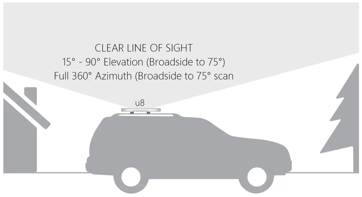 Figure 3. Land-mobile installation
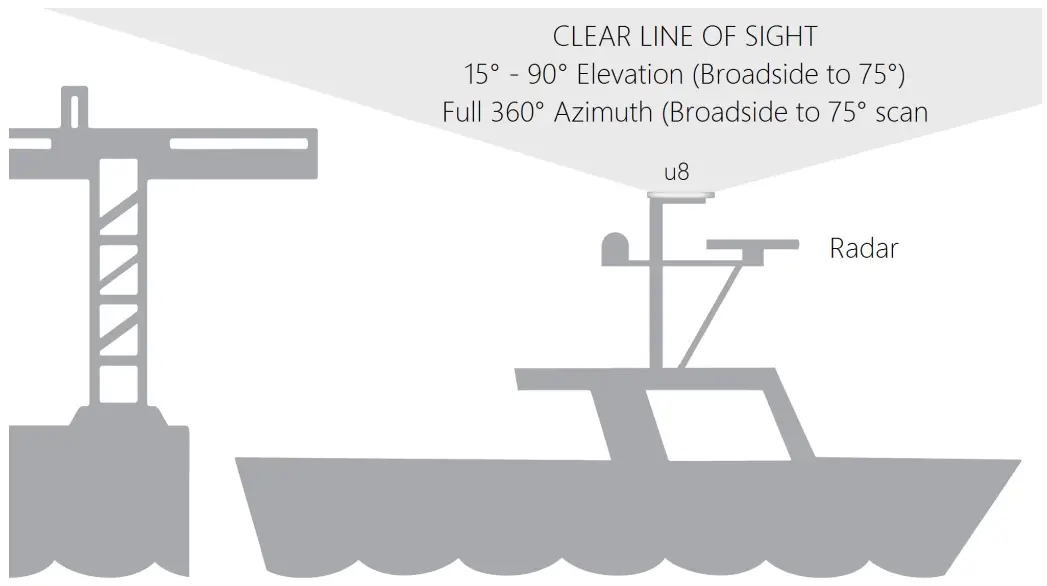 Figure 5. Maritime installation
Obtain u8 antenna status information
After the terminal has booted, you can obtain status information in several ways.
- Use Utilize the Kymeta Access application to view full terminal status.
- Open the shroud access panel to view status LEDs. Solid green LEDs indicate normal functioning, and blinking blue LEDs indicate connectivity. Refer to Appendix B. Network interfaces for full LED status indicator definitions.
- Open the shroud access panel and connect an Ethernet cable to the available port. This Ethernet connection provides Kymeta Administrative web-based UI access according to the directions in the section above relevant to your configuration.
Refer to the 700-00139-000 KymetaTM u8 antenna software user guide for details on interacting with the features of the Kymeta antenna. The software user guide provides you with details on all available features and modes of operation.
Customer support
Contact Kymeta customer support at [email protected] or call Kymeta at 1-855-525-6638 for urgent issues.
Revision history
|
Revision |
Change |
|
A |
Initial u8 satellite terminal version. |
Copyright and trademark information
©2021 Kymeta Corporation. All Rights Reserved. KYMETA, KYMETA CONNECT, MAKING MOBILE GLOBAL and CONNECTED BY KYMETA are trademarks of Kymeta Corporation, with registrations or pending applications in the U.S. and/or other countries. All other trademarks are the property of their respective owners.
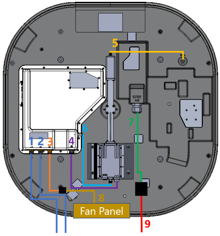
Appendix A. u8 satellite terminal cabling diagram
Six field-replaceable external cables [1, 2, 3, 4, 5, 6, and 9] reside under the u8 terminal shroud. The fan panel cable [8] can be replaced without removing the shroud. The power jumper cable [9] and Ethernet jumper cables [1 and 2] move connection interfaces outside the shroud to improve the installation experience.
|
 |
| Cable name and product code | Cable description |
| Ethernet 1 jumper cable (W57)Ethernet 2 jumper cable (W57)(U8ACC-00018-0) | Ethernet 1 jumper cable leads to the iQ 200 modem and Ethernet 2 jumper cable leads to the ACU.The behaviors of these two cables can be configured in the options file of the iQ 200 modem with help from the network operations center. The Ethernet ports are for a standard 10/100/1000 network and are the primary monitor and control (M&C) and data ports. They support multiple protocols for a web server (GUI), ACU-modem Interface (OpenAMIP), and an M2M (machine-to-machine) RESTful API. Installation engineers can make multiple connections with an external switch. |
| Fan power and control jumper cable (W47A)(U8ACC-00020-0) | This shielded Ethernet cable provides power and control to the fan panel. Since this cable supplies power, you cannot replace it with a standard non-POE Ethernet cable. Disconnect this cable at the outdoor-rated RJ45 connection halfway between the communication module and fan panel before removing the shroud entirely. The cable is attached to the fan panel cable (W47B). |
| BUC power, M&C cable (W44)(U8ACC-00019-0) | This cable connects the communication module and BUC. This cable provides power to the BUC and communication to set attenuation, mute, and read output power. |
| RX LNB cable (W46)(U8ACC-00016-0) | This LMR-195 cable connects the LNB to the antenna RX IN port. The cable requires a right-angle N-type connector at the antenna end to maintain the low profile of the antenna without sharp or protruding cable bends. The cable has standard N-type connectors at each end. |
| TX cable (W43)(U8ACC-00029-0) | This LMR-195 cable connects the BUC to the communications module carrying the modulated waveform at the intermediate frequency. The TX cable works in the frequency range from 950 MHz to 2150 MHz and passes a 10 MHz reference signal to the BUC. |
| Power main cable (W38A) | This cable is factory-installed and non-removable. The power main cable connects the power jumper cable (W38C) (U8ACC-00017-0) to the embedded power supply.When attaching the power main cable, check the keying: the threads may engage slightly when the connector is rotated by 180° from the correct alignment. Ensure that the threading fully engages. If the power main cable is correctly attached and fully seated, the metal nut at the end of the cable will cover the gasket on the embedded power supply input.⚠ Incorrectly seating the power connector will result in a short circuit, which will damage thecable and embedded power supply. |
| Fan panel cable (W47B)(U8ACC-00012-0) | This cable comes as a part of the shroud fan assembly. The cable is attached to the fan power and control jumper cable (W47A). The shroud fan assembly is field replaceable without removing the shroud. |
| Power jumper cable (W38C)(U8ACC-00017-0) | This cable is unterminated and can be connected to the u8 vehicle power kit (U8ACC-00001-0) using in-line splice blocks. If you want to use the AC-to-DC power kit (U8ACC-00002-0), replace the power jumper cable (W38C) (U8ACC-00017-0) with the cable provided with the power jumper cable (W38B) (U8ACC-00042-0) kit. |
Appendix B. Network interfaces
The u8 satellite terminal will ship to you with the following network interfaces:
| Local network | IP Mode | Static |
| Local network | IP Address | 192.168.44.2 |
| Local network | Netmask | 255.255.255.0 |
| Local network | Gateway | blank/empty |
| Local network | DNS Server | blank/empty |
| Admin VLAN | IP Mode | static |
| Admin VLAN | IP Address | 192.168.45.2 |
| Admin VLAN | Netmask | 255.255.255.0 |
| Admin VLAN | Gateway | blank/empty |
| Admin VLAN | DNS Server | blank/empty |
| Data VLAN | IP Mode | static |
| Data VLAN | IP Address | 10.12.12.2 |
| Data VLAN | IP Address | 255.255.255.0 |
| Data VLAN | Gateway | 10.12.12.3 |
| Data VLAN | DNS Server | 8.8.8.8 |
⚠ Failure to utilize the Data VLAN settings as shipped will result in connectivity issues with the antenna on all forms of u8 terminal connectivity except the wired Admin Ethernet Port as well as the elimination of OTA Metric transmission.If you use the antenna reset button, and depress the button for 5 seconds or longer, the u8 reverts to baseline network configuration:
| Network Interface | Network Setting | Baseline configuration (after reset) |
| Local network | IP Mode | static |
| Local network | IP Address | 192.168.0.10 |
| Local network | Netmask | 255.255.255.0 |
| Local network | Gateway | blank/empty |
| Local network | DNS Server | blank/empty |
| Admin VLAN | IP Mode | static |
| Admin VLAN | IP Address | 192.168.45.2 |
| Admin VLAN | Netmask | 255.255.255.0 |
| Admin VLAN | Gateway | blank/empty |
| Admin VLAN | DNS Server | blank/empty |
| Data VLAN | IP Mode | static |
| Data VLAN | IP Address | 10.12.12.2 |
| Data VLAN | Netmask | 255.255.255.0 |
| Data VLAN | Gateway | 10.12.12.3 |
| Data VLAN | DNS Server | 8.8.8.8 |
If you use the antenna reset button, be sure to replace the network configuration as defined by the tables above. Use the Kymeta web-based UI at Settings > Network to adjust the values to match the as-shipped configuration or as required. It is recommended you use the Admin Wired Ethernet Port to access and make corrections to reduce connectivity issues.
Appendix C. Device login information
The table below is a collection of devices, usernames, and passwords.⚠ Change your passwords using the Kymeta Access application or web-based UI. Leaving the passwords as the default is a security risk.
| Configuration | Device | IP address or SSID | Username | Password | Usage information |
| Terminal | Modem | 192.168.44.1 | admin | ! | Valid before commissioning |
| Terminal | Modem | 192.168.44.1 | admin | iDirect | Valid after commissioning when commissioning via Kymeta Broadband |
| Terminal | Antenna | 192.168.44.2 | admin | 2Cfg^Ant | Access the Kymeta web-basedUI. |
| Terminal | BUC | Use click-through from the Antenna Settings page | admin | admin | Making any changes to BUCconfiguration may result inunexpected transmission or maycause the BUC to become unreachable. |
Appendix D. LED status indicators
Antenna status LED indicator
| LED state | Indication |
| Off | Antenna not powered |
| Solid amber | Antenna powered but not successfully booted |
| Solid green | Antenna powered and successfully booted |
| Blink green, then solid green | Antenna reset successfully |
Satellite modem status LED indicator
| LED state | Web-based UI indicator | Satellite modem not powered |
| Off | OFF | Satellite modem not powered due to attempted operations outside of operating thermalspecification |
| Blinking amber | WAITING | Satellite modem powered but not successfully booted |
| Solid amber | BOOTING | Satellite modem successfully booted but LNB not detected |
| Fast blink green | ON | Satellite modem successfully booted and LNB detected |
| Solid green | READY | RX lock |
| Slow blink blue | RX LOCK | TX enabled |
| Fast blink blue | TX ENABLED | Satellite modem in the network |
| Solid blue | CONNECTED | Fault detected by built-in self-test |
© 2021 Kymeta Corporation. All rights reserved.
 report this ad
10 August 2021
[xyz-ips snippet=”download-snippet”]