Labgear High Gain Compact Digital Professional Aerial User Guide
High Gain Compact Digital Professional Aerial
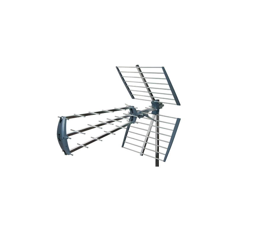
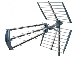
Congratulations on the purchase of your compact high gain digital aerial.The aerial is ideal for the reception of all available signals in medium and strong signal areas.The aerial is of particularly robust construction to ensure a long operating life and features:
- Tilting mast clamp for easy adjustment
- Easy dipole assembly
- Unique compact folding design
- 12dB gain
- Length: 790mm
- Electronic 75Ω balun with F type connection
Installation Instructions
For optimum results install the aerial using double screened CAIapproved digital coax cable (not supplied) and screened coaxoutlets (not supplied). You will need to fit the coax cable with an F type connector to connect to the aerial balun.
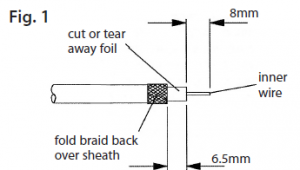
- Preparing the coax cable downlead: First slide the rubber weather boot provided over the aerial end of the cable. Strip the end of the cable as shown inFig. 1. Once you have stripped the cable, fold the braid back over the outer sheath making sure that no braid is touching the copper core, as this will cause a short on the cable and you will not get any signal. Also cut or tear away any foil shielding.
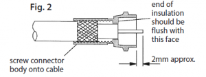
- Twist the ‘F’ connector supplied on to the prepared aerial end of the cable and trim the central conductor see Fig. 2. Once you have installed your aerial and run and secured the cable prepare the other end for connection to an outlet or coax plug (not supplied). For best results the aerial should be mounted on an outdoor aerial mast and pointed in the direction ofthe nearest transmitter* making sure it is in a position where the transmitter signal will not be obstructed by nearby trees and buildings. If you are in any doubt about the direction in which the aerial should be pointing or the orientation of the aerial (horizontal for main transmitter, vertical for relay transmitter) check your neighbours’ aerials.
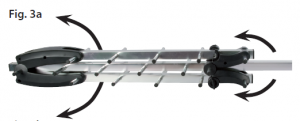

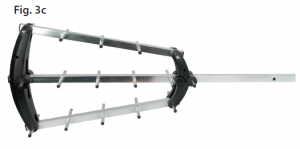
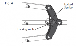
- Unfold the booms as shown opposte. To lock the booms in position turn both of the two knobs on either side of the aerial in a clockwise directionthrough 180˚ making sure that the arrows line up with the locked symbol – see Fig. 4.
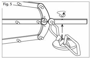
- Next fasten the balun to the underside of the mainboom as shown in Fig. 5. Make sure the balun is the right way round as shown in Fig. 4 and 8.
- Fix the reflectors to the main boom using the brackets and the bolt with wing nut supplied as shown below in Fig. 6.
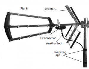
- Connect the aerial downlead to the ‘F’ socket on the aerial balun (be careful not to over tighten the F connector as this will damage the balun). Ensurethat the weather boot is correctly secured over the ‘F’ connector and socket – see Fig. 8. Make sure that the coax cable is routed as shown in Fig. 8 (through the middle of thelower reflector). Use insulating tape, to secure the the coax downlead to the reflector and mast.
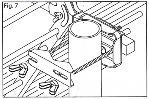
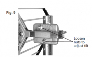
- Use the tilting mast clamp supplied to fix the aerial securely to the mast. To adjust the tilt angle loosen the two bolts, tilt to horizontal and then re-tighten nuts (see Fig. 9).

Troubleshooting
No picture: Check all connections from aerial to TV.Poor picture: Check all connections from aerial to TV.Check aerial is properly aligned to the correct transmitter. If the aerial has been loft mounted try mounting outside. Make sure new digital coax cable has been usedthroughout the installation. Check the transmitter signal is not obstructed by nearby trees or buildings. If in a very weak signal area or for long cable runs, installing a masthead amplifier will improve the signal. If in a strong signal area the signal strength may need to be reduced by fitting an attenuator.
Caution
When mounting the assembled aerial, always observe safety precautions and use the correct equipment. Unless you are competent in the use of ladders and otheraccess equipment ,do not work outdoors at roof height. If in any doubt, refer to a qualified aerial installer.
Useful Websites for Digital Advice:
To confirm that your home is in a coverage area, to find out which DTT channels should be available locally and to find out where your nearest transmitter is visit:www.dtg.org.uk/industry/coverage.html and enter postcode.To find out your nearest transmitter’s distance and compass bearing select Trade view from the top bar.
For further information, please contact: Customer careline: 08457 573479 (Local Rate – UK Only)Technical Support: www.philex.com/support/
Read More About This Manual & Download PDF:
References
[xyz-ips snippet=”download-snippet”]