LAMBDA Cartoni Professional Camera Support User Manual


1. Introduction
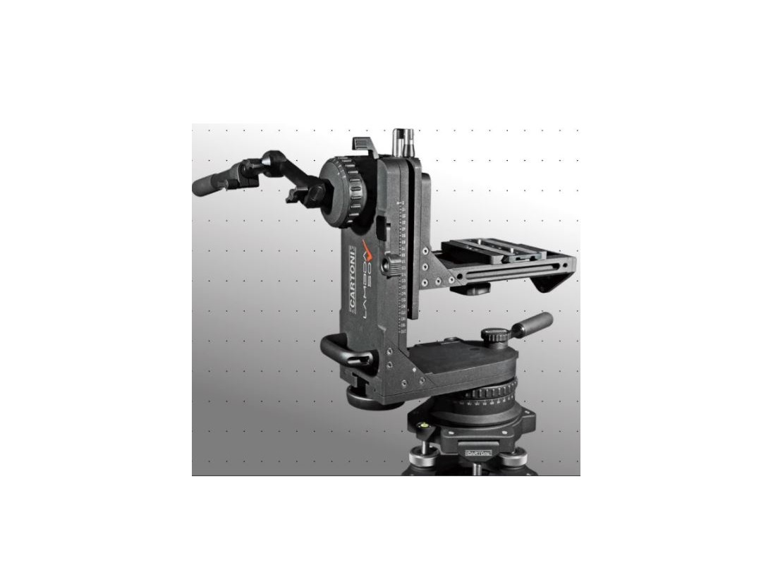
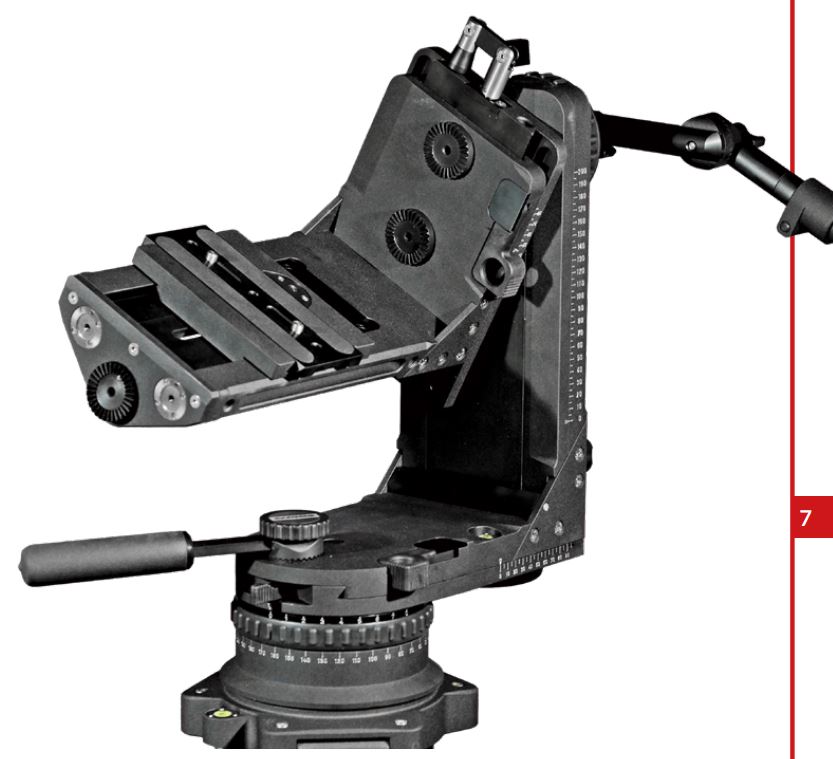
The Award winning CARTONI LAMBDA 50 Nodal Fluid Head is the only support that allows to set the nodal position with any Camera and pivoting 360° pan, tilt and roll, on the focal plan of any Camera.
The settings are achieved by graduated slides both horizontally and vertically with micrometric cranks for extreme precision. A smart system of orientable counterweight rods can be used when the slide run is not sufficient.
The LAMBDA 50 can be mounted on any classic support as tripods or dollies or used in underslung position from cranes and Jib arms.
Optional accessories as the 3rd AXIS, the orientable pan bar, steering wheel, eyepiece holder and the counterweight rods complete the most versatile of Camera supports.
- Before using the LAMBDA 50, please make sure to read this maintenance & user’s manual;
- Before installing the LAMBDA 50 on a tripod, crane, or any other support, check the support stability;
- Check that the Camera payload (including lenses & accessories) is lower than the maximum capacity of the LAMBDA 50;
- Before installing the Camera make sure the LAMBDA 50 is in good conditions and bares no evident damages.
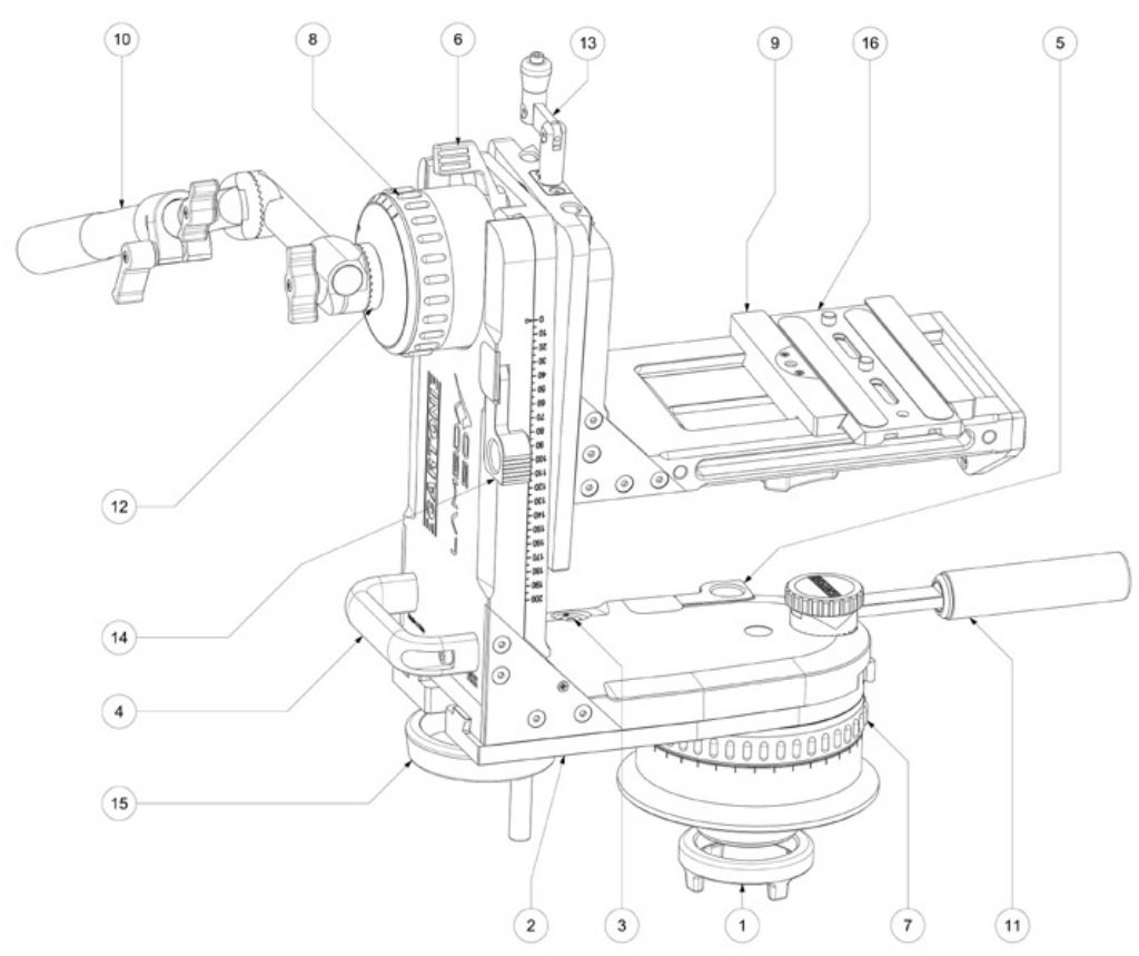
2. LAMBDA 50 – OPERATING ELEMENTS
- Fixing nut
- Horizontal slide
- Bubble level
- Transport handle
- Horizontal slide locking lever
- Tilt lock lever
- Pan drag selector
- Tilt drag selector
- Sliding base
- Main pan bar
- Short handle
- Tilt module rosette
- Inner slide crank
- Vertical lock safety lever
- Outer slide crank
- Camera plate
- Sliding camera support locking knob
- Inner slide
- Safety lever
- Safety knob
- Pan lock lever
3. Getting Started
- Install the LAMBDA 50 on the support (tripod, crane, dolly) and lock all the safety knobs.
- Place the LAMBDA 50 on the Mitchel base and rotate until it matches the steel notch; tighten the Fluid Head firmly by screwing in the fixing nut (1) underneath the flat base. WARNING: in under-slung position secure the LAMBDA 50 with the 2 ¼ inch nut. Check the bubble level (3) for horizontal position.
- Insert pan lock (21) and tilt lock (6) and turn both tilt drag selector (7) and pan drag selector (8) to position “0”.
- To release the Camera plate (16) pull down safety knob (20), unlock knob and disengage the Camera plate.
- Attach the Camera plate under the Camera assembly and firmly secure it with both screws. Try to place the Camera plate centered under the Camera system, keeping in mind the position of the center of gravity (CG).
- Slide the Camera in place on the sliding base (9) and center it by moving the base (9) left to right until you get a centered position. Release tilt lock (6) while holding the camera to prevent acci-dents and find a first Camera balance adjusting the sliding base (9) position releasing and locking it with the knob (17) under the sliding base. Lock the knob (17) when in place.
- Unlock horizontal slide locking lever (5) and set slide (2) in position, lock horizontal slide locking lever (5). The Camera assembly center of gravity (CG) should be aligned with the pan unit Axis in order to avoid unnecessary offsets and optimise the Fluid Head performance.
- Unlock safety lever (19) and set the main vertical slide length to fit the Camera dimensions by cranking up slide (18) with inner slide crank (13), lock safety lever (19) when in position.
- Unlock vertical lock safety lever (14) unfold crank (15) and crank it up or down until you find the Camera center of gravity (CG); at this point the Camera has to spin freely 360° degrees around the tilt position with the adjustable main pan bar (10). Lock vertical lock safety lever (14) and fold crank into housing position.
- Adjust pan (7) and tilt (8) selectors to the desired drag position and unlock pan lock (21).
- In case the shape and weight of the Camera system makes balance hard to obtain you can compensate offset components as long telephoto lens or viewfinder extensions with the appropriate counterweights and rods to be fixed on the osette (18).
- Counterweights and rods are essential to achieve the nodal setting.
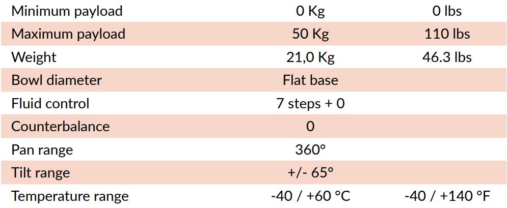
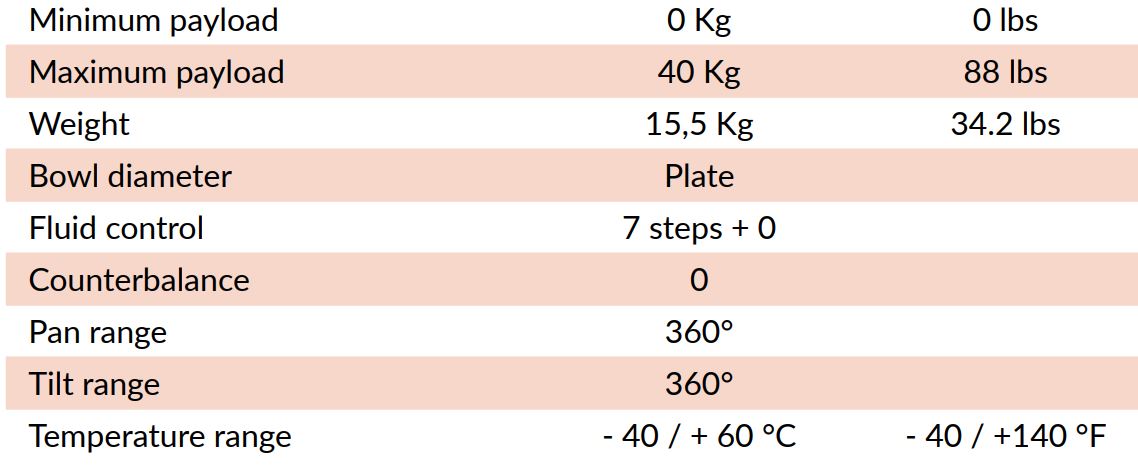
4. LAMBDA 50 – Specifications
LAMBDA 50 – 3rd AxIs
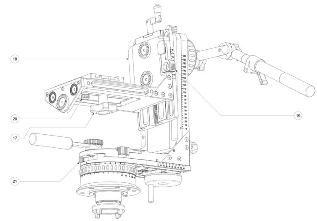
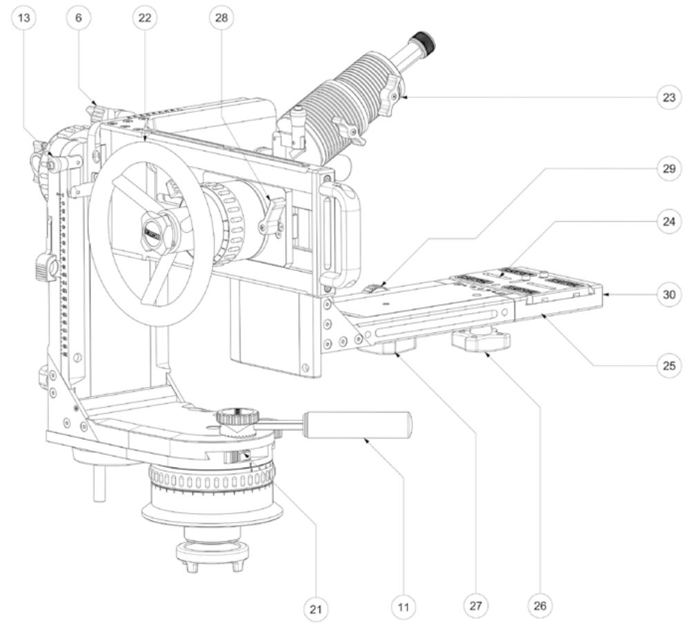
5. 3rd Axls – operating elements
6. Tilt lock lever11. Short handle13. Inner slide crank21. Pan lock lever22. Control wheel23. Counterweight24. Camera plate25. Camera plate safety knob26. Camera plate lock knob27. Camera plate slide lock knob28. Spin lock lever29. Camera plate slide control wheel30. Slide
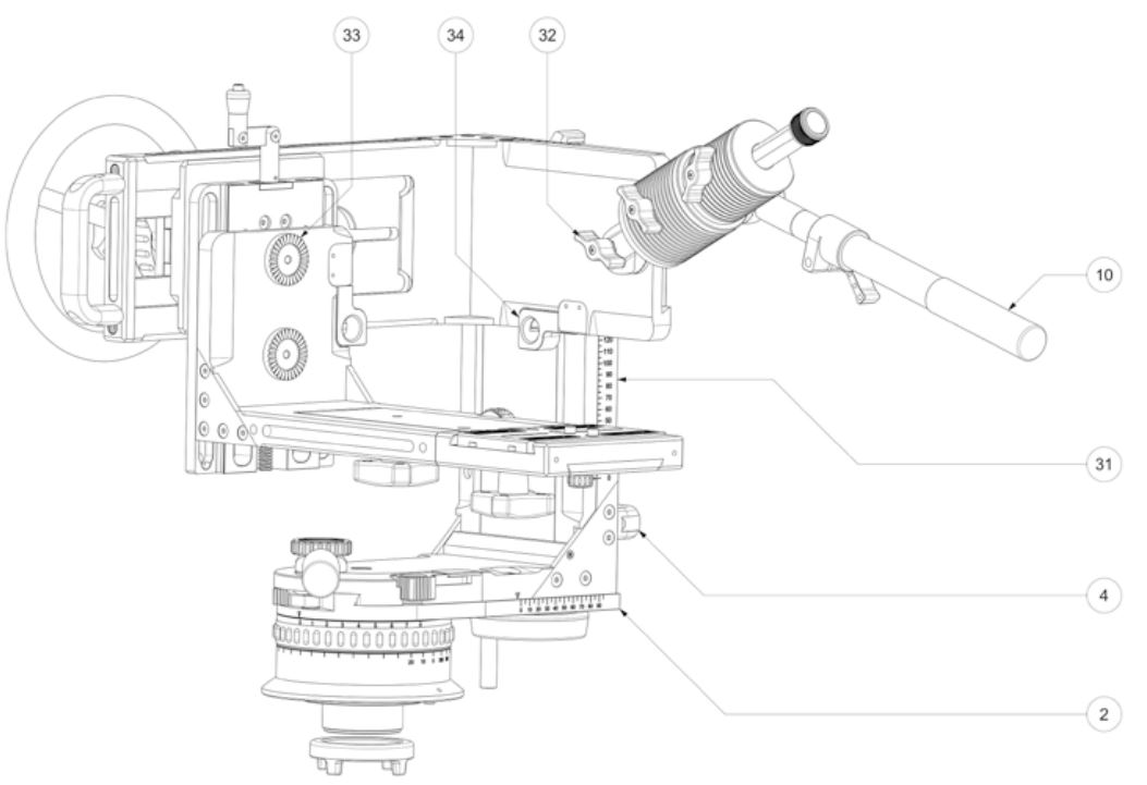
2. Horizontal slide4. Transport handle10. Main pan bar31. Vertical slide32. Counterweight lever33. Counterweight rosette34. 3rd AXIS plate lock lever
6. How to Mount the 3rd AxIs
Please see the video at:www.cartoni.com/products/fluid-heads/fluid-heads-sfx/hl5000ta-lambda50-third-axis/
- Place inner LAMBDA 50 slide (18) horizontally and lock in place with tilt lock lever (6).
- Unlock inner slide safety lever (19) and crank out inner slide (18) with crank (13) till to access safety Allen screw.
- Remove safety M5 screw with a 4mm Allen key.
- Lock inner slide safety lever (19).
- Crank inner slide (18) all the way with crank (13) and remove it.
- Slide in the 3rd AXIS assembly.
- Crank the 3rd AXIS assembly with crank (13) and lock 3rd AXIS plate with lever (34).
- Replace safety Allen screw and tighten.
- Mount control wheel (22) adjustable pan bar (10) and short handle (11).
7. CAMERA set-up WITH 3rd AxIs
- To release the Camera plate (4) pull down safety knob (5), unlock knob (6) and disengage the Camera plate.
- Lock the spin lock lever (8) the pan lock lever (12) and the tilt lock lever (13).
- Attach the Camera plate under the Camera assembly and firmly secure it with both screws.
- Slide the Camera in place on the sliding base (10) and lock the knob (6).
- Set the LAMBDA 50 main horizontal slide (14) and main vertical slide (15) at maximum ex-tension in order to prevent the Camera and its accessories to interfere with the LAMBDA 50 frame during the 360° movement. Operate the pan lock lever (12) and tilt lock lever (13) to lock and unlock.
- Set the Camera position by the turning wheel (9) and secure it with the Camera plate control knob (7). The Camera should move freely 360° on the roll Axis.
- Crank up or down the slide (10) to line up the rotation shaft of the control wheel (1) with the position of the Camera center of gravity (CG) (vertical Axis).
- Unlock the knob (6) and slide the Camera in place on the sliding base (10), to line up the ro-tation shaft of the control wheel (1) with the position of the Camera center of gravity (CG) (horizontal axis).
- The Camera is most probably out of balance so we have to correct the center of gravity (CG) of the entire system. Fix one or two counterbalance rods with weights to the rosette; adjust the angular position of the rod and weight position, until you fit the Camera in balance.
- This operation can require several fine tuning attempts, so please see the video at www.cartoni.com/products/fluid-heads/fluid-heads-sfx/hl5000ta-lambda50-third-axis/.
- Unlock the spin lock lever (8), the pan lock lever (12) and the tilt lock lever (13).
- The Camera has to be balanced and has to rotate 360° operating the control wheel (1) for roll rotation and the main pan bar (16) for pan and tilt rotation.
8. 3rd AXIS – SPECIFICATIONS
9. MAINTENANCE
When needed, with indoor use just clean the LAMBDA 50 and tripod with a soft cloth. Dirt accumulated during storage may be removed using a brush or Air-spray.
CARTONI products main mechanisms are sealed as they are also built for professional outdoor use.
However, used under rough conditions they will require special care. Salt water is very corrosive and can cause extreme damages. In attempt to avoid further damage the Fluid Head should be washed off with fresh water at the earliest opportunity and perfectly dried before storage.
Sand and dirt are abrasive and should be removed using a semi-stiff brush or Air-spray.
10. WARRANTY
All CARTONI Fluid Heads & Pedestals have a free of charge three (3) year warranty. Register your product at www.cartoni.com within 30 days from date of first purchase/invoice to receive further two (2) year warranty for the unsurpassed free five (5) year warranty.
Tripods, spreaders, dollies and all accessories are guaranteed one (1) year from the date of first pur-chase/invoice.
CARTONI warrants that the product supplied will – under proper use – be free from defects in workmanship and materials and agrees that it will, at its option, either repair or replace any defective part within duration of warranty from date of first purchase with no labour charge.
This warranty does not apply to any CARTONI product that has been damaged in shipping or handling, abused, misused, operated contrary to instructions for use, neglected, normal wear or tear, modified or changed in design or construction or serviced by unauthorized parties.
Repairs or misuse by any unauthorized parties will void this warranty.
Warranty claims must be submitted in writing – to the factory for verification or to an authorized distributor/dealer designated by CARTONI.
It is the end user’s responsibility when ordering to ensure that the products ordered conform to his requirements.
All freight of product to CARTONI must be prepaid. All implied warranties are limited to the time period set forth herein & subject to change without notice.
No liability can be accepted for any variation.
11. Accessories & Product Line
For the complete Accessories list & Product line please visit CARTONI’s official website www.cartoni.com.
Every product has an updated list of compatible items sorted by groups, with descriptions and technical data.
![]() CARTONI S.p.AVia di Portonaccio, 33/B – 00159 Rome (Italy)Phone +39 06 4382002Fax +39 06 43588293Email: [email protected]www.cartoni.com
CARTONI S.p.AVia di Portonaccio, 33/B – 00159 Rome (Italy)Phone +39 06 4382002Fax +39 06 43588293Email: [email protected]www.cartoni.com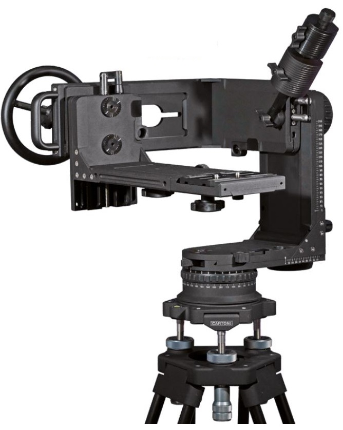
References
[xyz-ips snippet=”download-snippet”]