LANGRY LR-P40 Pull-off Tester
Instruction Manual

PREFACE
Your choice of the products made by Jinan Langrui Detection Technology Co., Ltd.( LANGRY) is greatly appreciated. We are committed to deliver you excellent products and satisfied sales services. Please carefully read the instructions prior to use.
- The instructions are prepared to provide the correct and complete descriptions of related products and data. However, we do not guarantee that there are no errors or omissions. Therefore, we will not bear responsibilities for any resulting consequences.
- LANGRY keeps the right of updating the instructions without prior notice.
- LANGRY bears no responsibilities for possible losses from data deviation or incorrect testing conclusion arising from instrument failure and other errors.
- When the instrument is put into operation, it means that you have carefully read and had full picture of all terms in the instructions, and you have fully agreed to all the terms in the instructions.
- LANGRY will not bear responsibilities for all the signed agreements violating the statement during the sales and services process not involving LANGRY.
Testing Standard
EN 1542-1999Products and systems for the protection and repair of concrete structures – Test methods – Measurement of bond strength by pull-off;
EN 1015-12Determination of adhesive strength of hardened rendering and plastering mortars on substrates;
EN 1348Adhesives for tiles – determination of tensile adhesion strength for cementitious adhesives
BS 1881-207Testing concrete- Recommendations for the assessment of concrete strength by near-to-surface tests
ASTM D 4541Standard Test Method for Pull-Off Strength of Coatings Using Portable Adhesion Testers
ASTM C 1583Standard Test Method for Tensile Strength of Concrete Surfaces and the Bond
Strength or Tensile Strength of Concrete Repair and Overlay Materials by Direct Tension (Pull-off Method)
ASTM D 7234-05Standard Test Method for Pull-Off Adhesion Strength of Coatings on Concrete Using Portable Pull-Off Adhesion Testers
ASTM D 7522Standard Test Method for Pull-Off strength of Fiber reinforced Plastics Bonded to Concrete Substrates
JGJ110 Testing standard for adhesive strength of tapestry brick of construction engineering
JGJ126 Specification for construction and acceptance of tapestry brick work for exterior wall
JGJ144 Technical standard for external thermal insulation on walls
Uses and Features
LR-P40 Pull-off Tester is used to test the bonding strength of building face brick and mosaics with walls or floors.
This instrument is a small hydraulic force measuring device. When testing the bonding strength of facing brick, it produces tension on the bonding material of facing brick through three-point counterforce support. When testing concrete, it USES the principle of post-install pull-out method and calculates the concrete strength by measuring the force needed to pull out and anchor solid inside concrete. The instrument is composed of perforating jack, hand pump, triangular chassis, forcemeasuring device and other components. It has a one camera dual use, novel structure, small size, convenient operation and complete functions.
The oil pump of the tester is loaded manually, and the rocker lead screw does not need to be shaken out in advance. It has the characteristics of small driving torque, comfortable and reasonable swing direction and continuous and uniform loading. Using single chip microcomputer as the core intelligent data processor, the battery inside the machine can be charged,
It has the functions of full digital display, automatic zero clearing (it can eliminate the measurement error caused by the friction force in the hydraulic system), peak holding selection, storing 500 pieces of data and over range display.
Technical parameters
The maximum pulling force of detector is 40 knChassis fulcrum inner diameter 120mmThe resolution of digital display is 0.01kNIndication error ≤± 1% F.SWeight (host) 4.3 kg
Structure features and working principle
The components of the tester are shown in Figure 1 and Figure 2
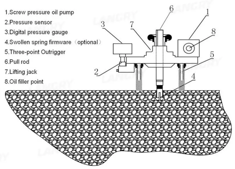
Figure 1 Tester working state diagram
Fig. 2 Top view of host
See Fig. 3 for the inspection accessories of facing brick
Fig. 3 Connection diagram of pull rod
Operating principle
As shown in Figure 1,Turn the handle to push the piston in the pump body to move, and the hydraulic oil will be pressed into the internal cylinder. Press in the connected pressure sensor and lifting Jack respectively, Thus pushing the piston up, driving the hand wheel and pull rod to apply tension to the standard test block. As the handle turns, the tension on the standard block increases gradually, and the oil pressure drops back to zero rapidly when the face brick is stripped. Because the pressure of the sensor is equal to the pressure in the jack, so, a force measuring device composed of sensor and digital display circuit can display the corresponding pressure value. At the moment of face brick stripping, the circuit will record the maximum oil pressure.
Intelligent pressure numerical display parameters
Fig. 4
The operating principle and application method of intelligent pressure numerical display
The intelligent pressure numerical display is mainly composed of pressure sensor and measurement display circuit, connected by data connection wire. The pressure sensor produces a voltage signal which is converted into a digital signal through a 20 bit A / D converter. After being processed by single chip microcomputer, the pressure value is displayed by LCD.
The panel of the intelligent pressure numerical display is shown in the figure 4.
Key function Description
Working State
The instrument has five display states: measurement, query, password, parameter modification and calibration.
Method of application
Operating instructions
Press the [![]() ] to switch between measurement and query status. The measurement status is displayed in two lines and the query status is displayed in one line.
] to switch between measurement and query status. The measurement status is displayed in two lines and the query status is displayed in one line.
In the measured state, when the measured value is greater than 0.500kN, the upper and lower rows will display the current measured value synchronously. When the current measured value falls below 0.500kN, the upper row will display the measured value, while the lower row will display the peak value. At this time, press [ ] to save the pressure value manually.
Note: The limiting pressure of the machine is 40kN, please do not use it with overpressure
In the measurement state, if the measured value is within the setting value of the allowable reset range (the instrument is set to 0.300kn from the factory), press the [ ] for 2 seconds to clear the measured value and take the current measured value as the zero point.
In the measurement state, when the measured value is within the setting value of zero tracking range (the instrument is set to 0.030kn from the factory), in order to eliminate the disturbance of internal resistance, the automatic zero tracking of the instrument is displayed as “0”.
In the query state, peak data records can be viewed. Press [![]()
![]() ] to turn the page to view all the records.
] to turn the page to view all the records.
In the query state, press the [ ] for 2 seconds to delete all recorded data and return to the measurement state.
Note: The deleted data cannot be recovered, Careful operation
Area parameter setting
Area parameter modification: in the measurement state, press and hold the [ ![]() ] key to enter the password state, enter the password 1234, and then press and hold the [
] key to enter the password state, enter the password 1234, and then press and hold the [ ![]() ] to enter.
] to enter.
Calibration of instrument
The calibration Settings are controlled by the password. The password is 1111. If the password is incorrect, the pressure calibration state cannot be entered.Steps: 1. press and hold the [ ] to enter the password state, input the password 1111, and then press and hold the [ ] for 2 seconds to enter the calibration state.
2.The upper row of the instrument displays “0%”, at this time, make sure that the instrument is not pressurized. When the pressure is at zero, press the [ ] key once, and the upper row of the instrument will display “10%”.
3. Then turn the handle and start to pressurize. Press the [] once when the proving ring displays 4kn, and the LCD upper row shows “20%”. Then press the [ ] when pressurized to 8KN.
4. The calibration of 10 broken line points in full range is completed by analogy. After the calibration of 100% range point is completed, the instrument will automatically exit the calibration state. Calibration accuracy can be maintained even when power is lost
Note: When calibrating, Don’t pay attention to the LCD display value in the lower row, as long as the display value is stable.
Broken line correction
Principle of broken line correction function:
After the instrument is connected to the input signal of the sensor, According to the comparison between the conversion value ,and the standard conversion value of each broken line point, the corresponding measurement value is obtained on the broken line of the interval. After the calibration of the measured value, the broken line correction function will be started automatically.
Check the broken line function:If 0mV, 2mV, 4mV, 6mV, 8mV and 10mV correspond to 0%, 20%, 40%, 60%, 80% and 100% respectively, the input (mV) position corresponding to the middle of any two calibration values shall also be near the middle of the input value corresponding to the two calibration values (deviation shall not exceed 0.5%).
Mode of operation
pre-operational check
Install the .three-point Outrigger on the chassis, Turn the oil pump handle clockwise, The piston of the jack should rise slowly. When it can not be shaken, the oil pump stroke reaches the limit, The Piston displacement of the jack should reach 8mm,Otherwise, hydraulic oil should be filled.
The oil filling method is:Unscrew the oil filling hole,Drop the oil into the oil hole, and slowly turn the handle anticlockwise so that the oil can be inhalated without air.When the maximum stroke is reached, gently rotate the handle clockwise so that the gas in the pipeline is discharged from the oil hole (oil can be discharged from the oil hole).The above process should be repeated several times, so that the oil is filled and the air in the hydraulic system is fully discharged, and then the oil hole screw is tightened.
Turn on the on-off switch of the intelligent pressure numerical display,characters should display normally on the LCD screen. When the battery voltage is too low to affect the use of the instrument, please charge the battery in time when the LCD displays “lobt”.
Application method of testing the bond strength of facing brick
Connect the pull rod with the thread of M12 with the standard test block set in advance. Install the tester. Turn on the intelligent pressure numerical display.
Turn the handle clockwise, and the piston rises about 2mm, When the piston is in quick contact with the pull rod nut but is not stressed, if the display value changes and is not zero, press the [down key] to subtract the friction force value in the hydraulic system.
Turn the handle and gradually increase the pulling force on the standard test block. When the ultimate pulling force is reached, the standard test block is detached from the tested body, At this time, the maximum pulling force value is maintained. Press the key to save the value, which is stored in the instrument,
After testing, reverse the handle to make the piston concave, and take down the pull rod and standard test block.
Product composition
- Host
- Charger
- Test block
- Instrument box
Precautions and maintenance
- the intelligent pressure value display is a precision instrument, so it should be shockproof and moisture-proof.
- There is discreteness between each sensor,The sensor and host of this tester have been calibrated together, and shall not be exchanged with other sensors or hosts.
- Keep the tester and accessories clean, and add lubricating oil to the rotating parts if necessary. The hydraulic system should be filled with clean N46 anti-wear hydraulic oil or similar oil.
- The tester has been calibrated before delivery, and it can be calibrated once a year according to the specific situation in the process of use.
- When the battery voltage is too low to affect the use of the instrument, please charge the battery in time when the LCD displays the word “LoBt”.
- The charger is a high-current charger, fully charged in 2 hours. Take off the charger in time after charging, so as not to overcharge the battery and affect its service life. 7)In order to ensure the correct use of the detector, please carefully read all the provisions in the manual and choose the test plan according to the relevant technical standards.
Manufacturer warranty
LANGRY guarantees that the tool is free from defects in materials and manufacturing processes when it leaves the factory, and the warranty is valid only if the user correctly installs, operates, maintains and cleans the tool in accordance with Langry’s operating instructions.
The warranty covers the free replacement or repair of damaged parts during the whole service life of this tool. If the parts need to be repaired or protected due to normal wear and tear, they are not covered by the warranty.
Other claims are not covered by the warranty unless there is a different provision under the specific law of the customer’s country. In particular, langry shall not be liable for any direct, indirect, incidental or inevitable damage, financial loss or additional expenses caused by or related to the improper use or abuse of this tool. Expressly exclude implied warranties of merchantability and fitness for a particular purpose.
 report this ad
In case of repair or replacement, the tool or relevant parts shall be sent to Langry’s market organization immediately after the failure is determined.
[xyz-ips snippet=”download-snippet”]