
INSTALLATION INSTRUCTIONS
Internal model: YSDC-36 YSDC-42Model No: 410TSDC36BNWH 410TSDC42BNBK
The limited lifetime warranty covers this ceiling fan, for residential use by the original purchaser, against defects in material or workmanship as follows:
If your LASALLE BRISTOL Ceiling Fan motor fails at any time during the lifetime of the original purchaser due to defects in material or workmanship, we will provide a replacement part free of charge.
If your Fan motor fails at any time within one year after the original date of sale to the original purchaser due to defectsin material or workmanship, we will provide labor to repair the defect, with the exception of take down/reinstallation, in material or workmanship, we will provide labor to repair the defect, with the exception of take down/reinstallation, free of charge. The original purchaser will be responsible for all labor costs after this one year period.
If no replacement parts are provided for any part of your Fan motor that fails at any time during your lifetime due to defects in material or workmanship, we will refund the original purchase price of your Fan.
If your Fan blades, remote controller / pull chain switch, reverse switch, or any accessory, except glass globes and light bulbs, fails at any time within one year after the original date of purchase due to a defect in material and workmanship, we will repair or, if we choose, replace the defective blades, switch, or accessory free of charge, with the exception of take down/reinstallation services.
If the original purchaser ceases to own the Fan, this warranty and any implied warranty, including but not limited to any implied warranty of merchantability or fitness for a particular purpose, become void. This warranty and any implied warranty, including but not limited to any implied warranty of merchantability or fitness for a particular purpose, do not cover glass globes, light bulbs, or finish on any metal portions of the Fan.
This warranty is in lieu of express warranties. The duration of any implied warranty of merchantability or fitness for a particular purpose, with respect to any LASALLE BRISTOL Ceiling Fan motor, blades, switch, or accessories, is expressly limited to the period of the express warranty set forth above for such motor, blades, switch, or accessories.
This warranty excludes defects, malfunctions, or failures of any LASALLE BRISTOL Fan that are caused by repairs by persons not authorized by us, use of parts or accessories not authorized by us, mishandling, improper installation, modifications or damage to the Fan while in your possession, or unreasonable use, including failure to provide necessary maintenance.
To obtain service, contact . You will be responsible for all insurance and freight or other transportation charges to our factory or service center. A copy of sales receipt is required in order to obtain service. We will return your Fan freightprepaid. Your Fan should be properly packed to avoid damage in transit, for we will not be responsible for any such factory or service center. A copy of sales receipt is required in order to obtain service. We will return your Fan freightprepaid. Your Fan should be properly packed to avoid damage in transit, for we will not be responsible for any such tprepaid. Your Fan should be properly packed to avoid damage in transit, for we will not be responsible for any such damages.
In no event shall LASALLE BRISTOL Fan be liable for consequential or incidental damages.
Some states do not allow the exclusion or limitation of consequential or incidental damages, in which case the above limitation or exclusion may not apply.
This warranty gives you specific legal rights and you may also have other rights which vary from state to state.
READ AND SAVE THESE INSTRUCTIONS.
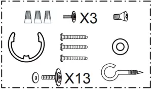
12 Volt DC Fan Package Contents:

1 2 3

![]()

4 5 6
7 8 9
Unpack your fan and check the contents.You should have the following items.
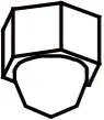
1.) Fan Motor Assembly2.) Housing3.) Turn Disk4.) Shaft Nut5.) Fan Blade (4 PCS)6.) Blade Bracket (4 PCS)7.) Wall Control8.) Assembly Kit9.) Installation Instructions
Dimension Reference:
A. 5″ B. 3-3/4″ C. 5-1/2″ D. 36″A. 5″ B. 3-3/4″ C. 5-1/2″ D. 42″
Exploded View Detail
Fan Motor Assembly →
Housing →
![]() ←Metal Washer
←Metal Washer
←Turn Disk
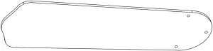 ←Fan Blade
←Blade Bracket
![]() ←E-clip Washer
←E-clip Washer
 ←Shaft Nut
Safety Instructions
READ ALL SAFETY INFORMATION AND INSTALLATION INSTRUCTIONS BEFORE YOU BEGIN TO INSTALL THE FAN AND SAVE INSTRUCTIONS.
- All set screws of the fan must be checked and retightened where necessary before installation.
- WARNING: To reduce the risk of personal injury do riot bend the blade brackets when installing the brackets, balancing the blades or cleaning the fan. Do not insert foreign objects between rotating fan blades.
- Before changing the fan direction, turn off the fan and wait for the fan blades to stop completely.
- The safeguards provided by these safety instructions and by the separate installation instructions are not meant to cover all possible conditions and situations that may occur. It must be understood that common sense, caution and care are factors which can not be built into this product. These factors must be supplied by the person(s) installing, caring for and operating the fan.
WARNING
- TO AVOID RISK OF ELECTRIC SHOCK, BE SURE TO SHUT OFF POWER AT THE MAIN FUSE OR CIRCUIT BREAKER BOX BEFORE INSTALLING OR SERVICING THIS FIXTURE. TURNING OFF THE ELECTRICAL POWER BY USING THE POWER SWITCH IS NOT SUFFICIENT TO PREVENT ELECTRICAL SHOCK
- SUPPORT DIRECTLY FROM BUILDING STRUCTURE.AND USE MOUNTING SCREWS PROVIDED WITH THE CEILING FAN.
- THE INSTALLATION HAS TO BE IN ACCORDANCE WITH THE NATIONAL ELECTRICAL CODE, ANSI/NFPA 70 AND LOCAL CODES. IF YOU ARE UNFAMILIAR WITH THE METHODS OF INSTALLING ELECTRICAL WIRING, SEEK THE SERVICES OF A QUALIFIED LICENSED ELECTRICIAN.
- TO REDUCE THE RISK OF INJURY, INSTALL THE FAN SO THAT THE BLADES ARE AT LEAST 7 FEET (2.1 METERS) ABOVE THE FLOOR AND AT LEAST 18 INCHES (0.5 METERS) FROM THE TIP OF THE BLADES TO THE WALL.
- WHEN USE IN RV, THE MAXIMUM CURRENT RATING OF FUSE SHALL NOT EXCEED 6A.
- TO AVOID RISK OF FAN, WALL CONTROL WIRES BURNING AND POWER CUTS, THE FAN HAS TO BE CONNECT WITH DC 12V POWER ONLY.
- TO REDUCE THE RISK OF FIRE OR ELECTRIC SHOCK,DO NOT USE THIS FAN WITH ANY SOLID-STATE SPEED CONTROL DEVICE.
INSTALLATION INSTRUCTIONS
IMPORTANT:
- BEFORE YOU BEGIN INSTALLATION, CAREFULLY READ ALL INFORMATION PROVIDED IN THE SAFETY INSTRUCTIONS AND INSTALLATION INSTRUCTIONS. IF IN DOUBT, CONSULT A QUALIFIED ELECTRICIAN.
- SAVE ALL INSTRUCTIONS.
NOTE: The fan weight is 36″:7.26Ibs(3.3kg),42″:7.71bs(3.5kg).Be sure the ceiling you are using is securely attached to the building structure and can support the full weight of the fan. Failure to do so can result in serious injury.
Installation Steps:
Turn OFF the electric circuit at the main fuse or circuit breaker box.
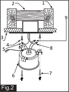
- Ceiling Joist
- Wood Member (2″ x 4″ Approx.)
- Ceiling
- Anchors
- Connect the blue (negative) wire from motor to the blue (negative) wire to the ceiling.
- Fan Motor Assembly
- Dry Wall Screw
- Connect the motor grounding wire to the grounding wire from the ceiling.
- Connect the white (positive) wire from motor to the white (positive) wire from the ceiling.
*** After making the wire connections, the wires should be spread apart. The blue (negative) conductor and yellow green (grounding) conductor on one side and the white (positive) conductor on the other side of the ceiling.*** The wire connection points should be turned upward and pushed carefully up into ceiling.
Tighten the fan motor assembly to the ceiling with three anchors and dry wall screws (ST6*25mm).( Make sure the ceiling is securely installed so that it will be able to support at least the fan weight.)
WARNING:1. SUPPORT DIRECTLY FROM BUILDING STRUCTURE.2. CONNECT TO DC 12V POWER ONLY.
Hang the roller of the safety cable on to the safety cable hook. Then push upward the little metal tube to secure the safety cable on the safety cable hook.
- Safety Cable Hook
- Safety Cable
- Safety Cable Hook
- Ceiling
- Wood Member (2″ x4″ Approx.)
- Ceiling Joist
Attach the safety cable hook to the ceiling and make sure the safety cable hook is covered by the fan canopy.
- Housing
- Ceiling
- Wood Member (2 x 4 Approx.)
- Ceiling Joist
- Screw
There are three mating holes on the housing. Lift housing and rotate it until the hole of housing match the hole of fan motor assembly, then install three screws(3/16″*12mm) into the mating holes and tighten in secure the housing to the fan motor assembly.
- Shaft Nut
- E-clip Washer
- Turn Disk
- Metal Washer
- Housing
- Ceiling
- Wood Member (2″ x 4″ Approx.)
- Ceiling Joist
Attach one metal washer onto the shaft of the fan motor, Lift turn disk and align the hole of turn disk onto the shaft of the motor and then insert it. One hand hold the turn disk, secure the e-clip onto the slot from the shaft of the motor to free your hands. Finally, tighten the turn disk by the shaft nut.
- Blade
- Washer
- Blade Screw
- Blade Bracket
Secure the blades to the blade brackets with blade screws (3/16″*12mm) and washers.
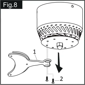
- Blade Bracket
- Turn Disk Screw
Remove screws and washers from turn disk first and then tighten blade brackets to turn disk using turn disk screws.
Change Blades Installation:
- Blade Bracket
- Turn Disk Screw
Remove screws and washers from turn disk first and then tighten blade brackets to turn disk using turn disk screws.

- Blade
- Washer
- Blade Screw
- Blade Bracket
Remove the blade screws and fiber.
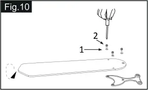
- Washer
- Blade Screw
Change the obverse blade to the back side,reinstall the screws and fiber.
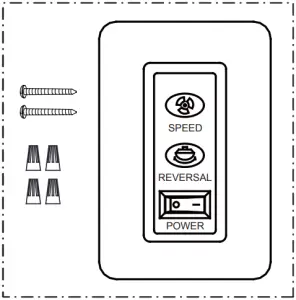
Wall Switch Installation:
- Junction Box
- Wall Switch
- Wall Switch Cover
- Wall Switch Screw
- Install the wall switch in a junction box as shown.
- The DC12V positive and negative wire need to be protected before it through the opening to reduce the chance of wire damage.
- Wire connection:a. Connect the white (positive) wire from junction box to the white (positive) wire from the wall switch with a wire connector.b. Connect the blue (negative) wire from junction box to the blue (negative) wire from the wall switch with a wire connector.c. Connect the red (positive) wire from wall switch to the battery positive (+) wire with a wire connector.d. Connect the black (negative) wire from wall switch to the battery negative (-) wire with a wire connector.e. Carefully push the wire connection points into wall outlet box. Secure the wall switch with two wall switch screws provided in wall switch.f. There are four slots on the wall switch and four studs on the wall switch cover. Install two studs on the bottom of the wall switch cover into two slots on the wall switch and then push wall switch cover until it securely on the wall switch.
Warning:1. Connect to DC 12V Power Only.2. To reduce the risk of fire, or electric shock, do not use this fan with any other solid-state speed control.
Turn on the electric power at the main fuse or circuit breaker box.
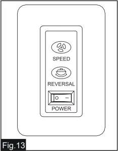
FUNCTION OF WALL SWITCH:
- Turn on the power and check operation of fan.
- Press “POWER” button at “—” position to turn on the fan at high speed.
- Press “POWER” button at “o” position to turn off the fan.
- Press “SPEED” button to change fan speed.PRESS SPEEDSOne time 100%–High SpeedTwice 75%–Medium HighThird 50%–MediumFourth 25%–Low
- Press “REVERSAL” button to sets direction of fan rotation.a. Turn on the fan at first time without setting, the blades are turning clockwise to create an upward motion, pulling cooler air near the floor up toward the ceiling, forcing warmer air downward, this good for air circulation and suitable for winter.b. Press “REVERSAL” button to sets the fan to turn counterclockwise, which will create a downward motion and a cooling effect. If you can feel cool air blowing down on your skin, then that means the fan is turning counterclockwise, this is suitable for summer.
 report this ad
Troubleshooting GuideIf you have difficulty operating your new ceiling fan, it may be the result of incorrect assembly, installation or wiring. If you experience any faults, please check this Troubleshooting Guide. If a problem cannot be remedied or you are experiencing difficulty in installation, please call our Customer Service Department (1-800-887-6326).
| PROBLEM | SUGGESTED REMEDY |
| 1. If fan does not start: | CAUTION: Connect to DC 12V Power Only before turn on the fan.
|
| 2. Noisy Operation: |
|
| 3. Excessive wobbling: | All blades are weighted and grouped by weight. Natural woods vary in density which could cause the fan to wobble even though all blades are weight-matched. The following procedures should eliminate most of the wobble. Check for wobble by following the steps listed below.
|
[xyz-ips snippet=”download-snippet”]