UNIVERSAL LED DIMMERMANUAL INSTRUCTIONItem NO. LCB675581
This dimmer has been developed specially for Dimmable LED Lamps.
Most dimmable lamps have an optimum performance mode – Lead ing Edge or Trailing Edge. The advanced technology used to control the laad results in the flicker-free dimming of lamps and drivers. This technology also eliminates the need to differentiate between leading and trailing edge lamps that will prevent the lights trom flickering. See “Changing the Dimmer Mode”below.
Additionally, the minimum brightness setting of the dimmer can be adjusted to achieve the optimum dimming range for a particular laad. See “Adjusting the Minimum Brightness” below.
You may need to refer to these instructions if you change your lig hts to a different type at a later date sa please keep them for reference.
SPECIFICATION
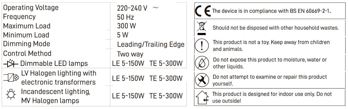
Warning!Certain light sources may not behave according to their power rating when used with a dimmer. An overlaad will result in the safety features switching the dimmer off. We always recommend to connect under the suggest laad.
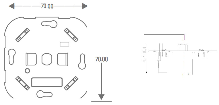
Dimension
INSTALLATION
READ THERE INSTRUCTIONS CAREFULLY. INCORRECT INSTALLATION MAY DAMAGE THE DIMMER BEYOND REPIRE.
- Switch off the mains supply before commencing the installation.
- If removing the existing switch, disconnect the wiring from the switch terminals at the rear and take note of the present wiring of the switch and the marking on the terminals.
- Ensure that any mounting box is free of plaster lumps or projecting screw heads. Most models can be fitted into a box with a minimum depth of 25mm. These dimmer switches can be installed in boxes with two mounting lugs only. Other mounting lugs need to be removed or bent flat.
- Terminate the dimmer switch in accordance with the diagrams in the Wiring Instructions section. Take care that no bare wires project out of the terminals. Keep wires together in a terminal if they were together in your old switch.
- After connecting the wires screw the dimmer switch gently into the wall box so that the front plate does not distort or crack. Do not trap the wiring between the rear of the dimmer and the back of the wall box.
- Once installation is complete, switch on the mains supply. When switching on the dimmer for the first time you might need to set up the min. brightness and max. brightness, dimming mode as well.
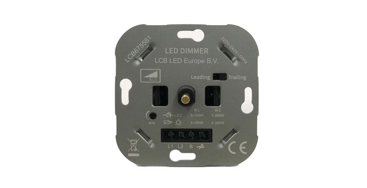
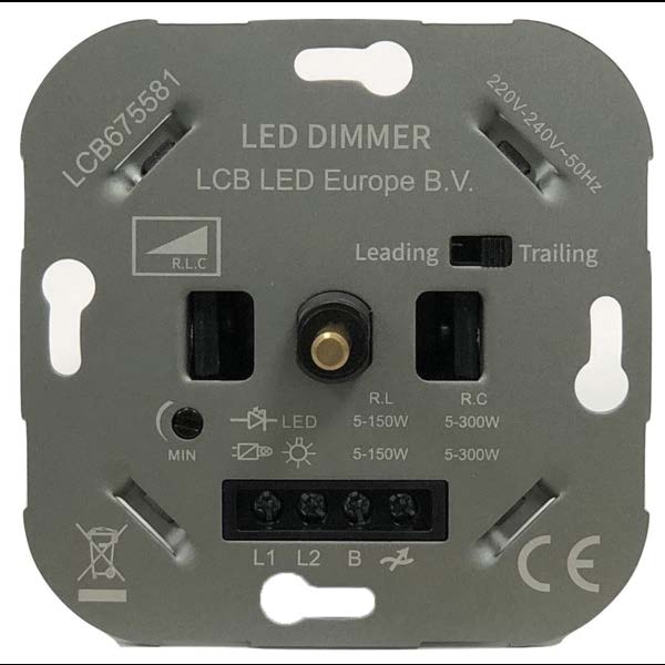
OPERATION
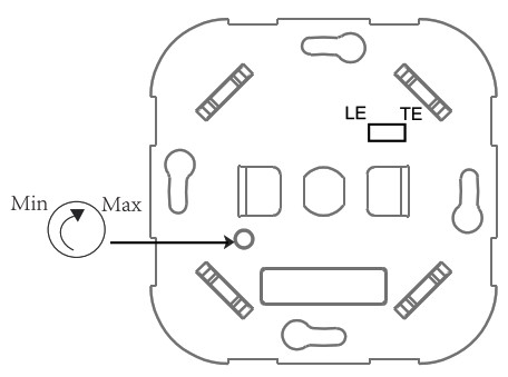
- Changing the Dimmer ModeThe dimming mode can be easily changed by a switch on the plate. Switch to the left means you are in Leading edge (LE) mode. Switch to the right means you are in trailing edge (TE) mode.
 Please remeber the leading edge mode connecting load should always be lower than trailing edge mode.
 - Adjust the min. & max. brightness level• Ensure the lamp module is switched OFF• Clockwise the VR ( Variable Resister) to increase the brightness at min. & max. point.• Anti-clockwise the VR to decrease the brightness at the min. & max. point.
 Please remeber the leading edge mode connecting load should always be lower than trailing edge mode.
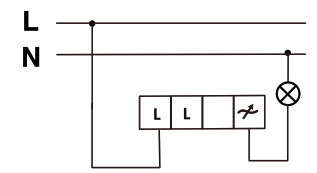
WIRINGThis dimmer switch is suitable for 1 or 2 way lighting circuits.There are three terminals per module.• 1-way CircuitsIn 1-way lighting circuits, each lamp is controlled by one dimmer switch.Follow the wiring in Figure 1.L live supply, ![]() load
load
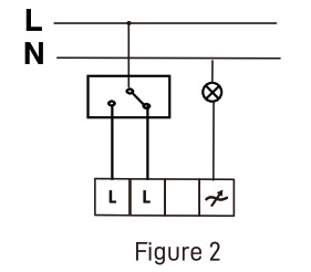
• 2-way CircuitsWhen controlling the load from two positions, it is only possible to have one dimmer switch. The other needs to be a 2 way switch 2-way lighting circuits have two switches turning the same lamps on and off from two different locations however only one of these can be a dimmer switch, the other must be a 2-way switch. Follow the wiring in Figure 2.L live supply, ![]() load
load
[xyz-ips snippet=”download-snippet”]