![]()
USER MANUALFixedWingFLightController + Pixel OSD
![]() Verv2.2FW 3.2+LeFeiRC2020/4/20
Verv2.2FW 3.2+LeFeiRC2020/4/20
WARING:Please strictly observe the relevant national laws and regulations for safe flight. We do not advocate flying high, flying far, experiencing the fun of the model airplane in a fully safe environment, and creating a good environment for model airplane sports! Before using flight control, you must fully understand the various safety details and deeply understand that the flight is risky. It is impossible to be completely reliable on the equipment and any electronic products on the aircraft. You should use the Sinan (SN_L) fixed-wing flight control to evaluate the product and use the system according to relevant regulations.The system provider does not use the product for any use. Responsible for direct or indirect losses and consequences.
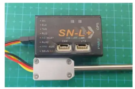
INTERFACE:
![]()
- POWER① VTX, CAM, is powered by PMU 12V② GPS, FC is powered by PMU 5V③ Servo and receiver are powered by external BEC
- LED
RED LED GPS GREEN LED RC OFF disconnect FLASH Lose control FLASH Satellite < 7 ON normal ON Satellite > 6 1 1 - CONNECTOR
AIL AIL servo ELE ELE servo THR ESC signal RUD RUD servo AS / AUX1 Airspeed connector/AUX1 AUX2 AUX2 PPM / AUX3 PPM connector/AUX3 SBUS SBUS VTX Video transmitter CAM camera GPS GPS/ upgrade FW / tune parameters - HOW TO CONNECT DIGITAL VIDEO TRANSMITTER
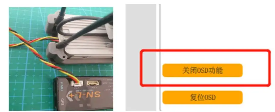
 GCS ver1.5.0If you do not use the OSD function, please close it by SN_GCS.Set telemetry port as <DJI> by OSD <MISC> or SN_GCS.
 - HOW TO CONNECT SN_GCS (GPS port baud:115200)Connect to GCS by our upgrade tool board or Bluetooth.
 GCS ver1.5.0If you do not use the OSD function, please close it by SN_GCS.Set telemetry port as <DJI> by OSD <MISC> or SN_GCS.
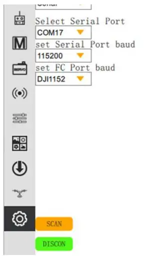
FLIGHT MODE:
| MANUAL | Remote control directly controls the aircraft |
| STAB | Auto level |
| HORIZON | ACRO mode + STAB mode |
| RTH | Return to home |
| HOVER | Altitude hold and cycle。 |
| ALTHOLD | Aircraft hold altitude and flight route ( with GPS ) |
| HEAD LOCK | Keep on the route |
| ACRO | Gyro mode |
| SUB-MODE | Switch mode to slave mode |
- RTH MODE① You need to set < CRUISING SPEED >, < CIRCLE RADIUS >, < RTH SAFE ALTITUDE > and < RTH ALTITUDE > in the RTH mode.< RTH SAFE ALTITUDE > refers to the height that the aircraft needs to maintain when returning home; for example, The aircraft begins to return home at an altitude of 2000 meters. At this time, when the < RTH SAFE ALTITUDE > is set to 500m, the aircraft will slowly descend to 500 meters and then return home; If the < RTH SAFE ALTITUDE >is less than 500 meters, the aircraft will climb to a height of 500 meters first.< RTH ALTITUDE > refers to the altitude when the plane is hovering
- ALTHOLD MODEFC will lock the route if GPS is connected. Otherwise only hold altitude. The throttle stick is placed in the middle position, meaning that the current speed is equal to the set speed. Move up or down to increase or decrease speed.
-
GEO-FENCE:Enter the OSD setting item < AUTO PARAMETER>: < GEOFENCE DISTANCE>: The aircraft will automatically switch to the home mode when flying over this distance. Cancel the home mode by quickly dialing the mode stick; ‘0’ means to close the radius fence limit.< GEOFENCE ALTITUDE>: If the aircraft exceeds this altitude, the altitude will be forcibly lowered; ‘0’ means to close the altitude limit.
SWITCH FLGHT MODE:
- HOW TO SET FLIGHT MODE① Set by SN_GCS• The stroke range covers the position of the switch.• Do not repeat the stroke range of different modes.• Only one mode is allowed to be in the valid range at a time.② Set by OSDExample:
| Position | Mode switch | SUB-Mode Switch |
| 1 | STAB | RTH |
| 2 | SUB-MODE | HOVER |
| 3 | ALTHOLD | MANUAL |
INSTALLATION:
- PMU MODULE
- INSTALL DIRECTION OF FC
4 install direction:<BASE FUNCTION> -> <AP DIRECTION>
0° Arrow point to head 180° Arrow point to the rear 90° Arrow point to the left side of the nose 270° Arrow point to the right side of the nose The FC installation should try to avoid the vibration source and keep away from the motor; try to install it near the center of gravity. Be sure to recalibrate the level after changing the installation direction - HOW TO CONNECT SERVO
Type / Interface AIL ELE THR RUD Wing SERVO 1 SERVO 2 THR RUD SERVO T tail AIL SERVO ELE SERVO THR V tail AIL SERVO ELE SERVO1 THR ELE SERVO2 How to configure the throttle differential: Just configure one of the AUX ports such as AUX1 as the <THR> function, the flight control will differentially control the throttle channel and the AUX1 channel; Note that the differential control map is the direction stick, please Confirm that the direction of the throttle differential is correct, and set the differential amount in < SERVO >-> < THRROTLE DIFF >. The greater the differential amount, the faster the flight turns, but it is easier to stall.
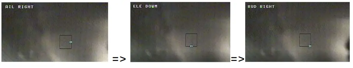
- CORRECT CONTROL SURFACES MOVEMENT
- CONNECT AIRSPEED*AUX1 channel set as <NONE>
- TELEMETRY PORTPort TX as telemetry port.TX port can be set as <MAVLINK57600> / <MAVLINK115200> / <DJI>.*If you set it as <MAVLINK57600>, the airspeed meter could not work normally.


 *AUX1 channel set as <NONE>
REMOTE CONTROLLER
- Set RC channel travel rangePlease set range at OSD or SN_GCS:Enter OSD menu <REMOTE>:CHANNEL MAX: select and pull throttle stick to the max position; hold throttle and exit.CHANNEL MID: select and exit.CHANNEL MIN: select and pull throttle stick to min position; hold and exit.
- Learn RCWhy should learn RC?To let FC learn channel direction and channel type (AETR or TAER).STEP1: power on FC.STEP2: pull RUD channel to max position (right or left) before OSD starts picture show.STEP3:
- FAILE SAFE① SBUS receiver can automatically identify the out-of-control, auto switch to RTH mode (when GPS satellite > 6).② PPM receiver cant auto-identify out of control, you should set failsafe mode by yourself.Check the fail-safe mode before takeoff
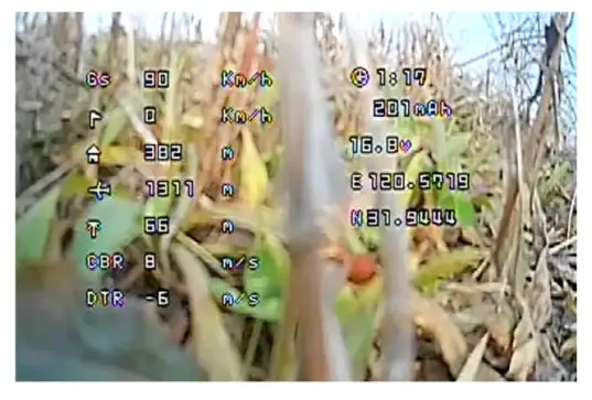
OSD:
- Flight SummaryAfter landing, the flight summary will be displayed.Quick switch flight mode to cancel summary window.
- How to enter the OSD menuQuick switch CH5. Cant enter the OSD menu when flying.
- How to select a menu
| enter the OSD menu item | AIL channel right |
| Exit OSD menu | AIL channel left |
| Move the cursor | ELE channel up or down |
PREFLIGHT CHECKLIST:
- Unlock throttle① Make sure you have set < MIN CHANNEL VALUE>② GPS Satellites fixed
- CHECK ACCEL HEALTH <OSD>-<SCOPE>-<HEALTH>① The vibration is in good condition. When the plane is lying flat, the vibration point is scattered within the two warning lines.② The vibration is large, and most of the vibration points fall outside the warning line, which easily leads to the FC can’t calculate the correct attitude
- CALIBRATE LEVEL<SENSOR>-<CALI LEVEL>① Ensure that the aircraft is level and static during horizontal calibration.② Horizontal calibration is required after changing the mounting direction.③ If you have not calibrated for a long time or the temperature difference has changed too much, you need to recalibrate.
-
SENSITIVITY ADJUSTMENT① <BASE FUNCTION>-<AIL BASE GAIN> -<ELE BASE GAIN> -<RUD BASE GAIN>: The larger the value, the faster the reaction speed and the excessive jitter.② < BASE FUNCTION >-<FEED FORWARD GAIN>: The larger the value, the faster the response joystick will be, and the jitter will be exceeded.③ Adjustment Steps:Step1:set <FEED FORWARD GAIN>, normally reduce the feed-forward gain to 45Step2:set the <AIL BASE GAIN> -<ELE BASE GAIN> -<RUD BASE GAIN>. You can fly by default, then increase or decrease the sensitivity according to the state of flight.④ PID speed FactorPRINCIPLE: the faster the speed, the smaller the rudder surface sensitivity should be. The greater the value, the greater the speed involved in PID control.EXAMPLE: when the speed of the aircraft is very fast, the aircraft begins to shake; then you can increase <ADVACE FUNC>-<STABGAIN>-<SPEED PID FACTOR>value.⑤ Altitude hold gain <ADVANCE FUNC>-<STAB GAIN>-<ALT HOLD GAIN> IN RTH,ALT-HOLD, WAY-POINT mode, if aircraft action like this in the pitch direction:

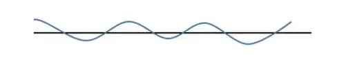 please decrease alt-hold gain.
FLIGHT & CONTROL
- AUTO TAKEOFF:① AltHold mode: Push the throttle to enough power and the aircraft will automatically climb to a height of 20m.② RTH mode:Way1: push the throttle channel away from the zero position, give plain a speed until the motor starts.Way2: push the throttle channel away from the zero position, shake the aircraft, until the motor starts. Aircraft will auto climb at 30m.
- SPEED CONTROL① Disconnect AirspeedSpeed is controlled by the ground speed, cruising speed set in <ADVANCE FUNCTION>-<CURISE SPEED>.② Connect AirspeedSpeed is determined by airspeed, Preventing the wind from flying in the head, causing the ground speed to be too small, please set <MINIMUM GROUND SPEED>.
FIRMWARE UPGRADE
***Get firmware and upgrade software: www.lefeirc.com or connect [email protected]
report this ad
- connect upgrade tool to computer, and install server if need.
- Connect to the right COM port.
- Click <open> button, and load firmware. do not power FC!!!
- Click <write> button, power on FC
- Wait until progress 100% complete.
References
[xyz-ips snippet=”download-snippet”]