Lenco Direct Drive Turntable with USB Recording User Manual

IMPORTANT SAFETY PRECAUTIONS
- Read Instructions All the safety and operating instructions should be read before this product is operated.
- Retain Instructions The safety and operating instructions should be retained for future reference.
- Heed Warnings All warnings on the appliance and in the operating instructions should be adhered to.
- Follow Instructions All operating and use instructions should be followed.
- Water and Moisture Do not use the appliance near water – for example, near a bathtub, washbowl, kitchen sink, laundry tub, in a wet basement, or near a swimming pool, and the like.
- Carts and Stands The appliance should be used only with a cart or stand that is recommended by the manufacturer. An appliance and cart combination should be moved with care. Quick stops, excessive force, and uneven surfaces may cause the appliance and cart combination to overturn.

- Wall or Ceiling Mounting The product should not be mounted to a wall or ceiling.
- Heat Appliance should be situated away from heat sources such as radiators, heat registers, stoves, or other appliances (including amplifiers) that produce heat.
- Power Sources This product should be operated only from the type of power source indicated on the rating label. If you are not sure of the type of power supply to your home, consult your product dealer or local power company. For products intended to operate from battery power, or other sources, refer the operating instructions.
- Grounding or Polarization This product may be equipped with a polarized alternation-current line plug (a plug having one blade wider than the other). This plug will fit into the power outlet only one way. This is a safety feature. If you are unable to insert the plug fully into the outlet, try reversing the plug. If the plug should still fail to fit, contact your electrician to replace your obsolete outlet. Do not defeat the safety purpose of the polarized plug.
- Power-Cord Protection Power-supply cords should be routed so that they are not likely to be walked on or pinched by items placed upon or against them, paying particular attention to the cord in correspondence of plugs, convenience receptacles, and the point where they exit from the appliance.
- Cleaning The appliance should be cleaned only as recommended by the manufacturer. Clean by wiping with a cloth slightly damp with water. Avoid getting water inside the appliance.
- For AC line powered units Before returning repaired unit to user, use an ohm-meter to measure from both AC plug blades to all exposed metallic parts. The resistance should be more than 100,000 ohms.
- Non-use Periods The power cord of the appliance should be unplugged from the outlet when left unused for a long period of time.
- Object and Liquid Entry Care should be taken so that objects do not fall and liquids are not spilled into the enclosure through openings.
- Damage Requiring Service The appliance should be serviced by qualified service personnel when:
- The power-supply cord or the plug has been damaged; or
- Objects have fallen, or liquid has been spilled into the appliance; or
- The appliance has been exposed to rain; or
- The appliance does not appear to operate normally or exhibits a marked change in performance; or
- The appliance has been dropped, or the enclosure damaged.
- Servicing The user should not attempt any service to the appliance beyond that described in the operating instructions. All other servicing should be referred to qualified service personnel.
- Ventilation Slots and openings in the cabinet are provided for ventilation and to ensure reliable operation of the product and to protect it from overheating, and these openings must not be blocked or covered. The openings should never be blocked by placing the product on a bed, sofa, rug, or other similar surface. This product should not be placed in a built- in installation such as a bookcase or rack unless proper ventilation is the manufacturer’s instructions have been adhered to.
- Attachments do not use attachments not recommended by the product manufacturer as they may cause hazards.
- Accessories Do not place this product on an unstable cart, stand, tripod, bracket, or table. The product may fall, causing serious injury to a child or adult, and serious damage to the product. Use only with a cart, stand, tripod, bracket, or table recommended by the manufacturer, or sold with the product. Any mounting of the product should follow the manufacturer’s instructions, and should use a mounting accessory recommended by the manufacturer.
- Lightning For added protection for this product during a lightning storm, or when it is left unattended and unused for long periods of time, unplug it from the wall outlet and disconnect the antenna or cable system. This will prevent damage to the product due to lightning and power-line surges.
- Replacement Parts When replacement parts are required, be sure the service technician has used replacement parts specified by the manufacturer or have the same characteristics as the original part. Unauthorized substitutions may result in fire, electric shock, or other hazards.
- Safety Check Upon completion of any service or repairs to this product, ask the service technician to perform safety checks to determine that the product is in proper operating condition.
SAFETY INSTRUCTIONS
CAUTION
![]() DO NOT OPEN RISK OF ELECTRIC SHOCK
DO NOT OPEN RISK OF ELECTRIC SHOCK
![]() CAUTION: To reduce the risk of electric shock, do not remove any cover. No user-serviceable parts inside. Refer servicing to qualified service personnel only.
CAUTION: To reduce the risk of electric shock, do not remove any cover. No user-serviceable parts inside. Refer servicing to qualified service personnel only.
![]() The lightning flash with arrowhead symbol within the equilateral triangle is intended to alert the use to the presence of un-insulated “dangerous voltage” within the product’s enclosure that may be of sufficient magnitude to constitute a risk of electric shock.
The lightning flash with arrowhead symbol within the equilateral triangle is intended to alert the use to the presence of un-insulated “dangerous voltage” within the product’s enclosure that may be of sufficient magnitude to constitute a risk of electric shock.
![]() The exclamation point within the equilateral triangle is intended to alert the user to the presence of important operation and maintenance (servicing) instructions in the literature accompanying this appliance.
The exclamation point within the equilateral triangle is intended to alert the user to the presence of important operation and maintenance (servicing) instructions in the literature accompanying this appliance.
CAUTIONTo prevent electric shock, do not use this polarized plug with an extension cord, receptacle or other outlet unless the blades can be fully inserted to prevent blade exposure.
QUICK-START
Turntable Quick-Start:
- Changing Platter SpeedUse the RPM selectors to change the platter speeds. The 33-rpm and 45-rpm speed selectors change the platter rotation respectively.
- Starting and Stopping the PlatterUse the START/STOP BUTTON to switch back and forth between platter rotation and pause modes.
- Pitch Control
- The pitch adjustment is a fine adjustment to the platter’s RPMs.
- The pitch adjustment is variable and may be adjusted between -10% and +10% of the platter-selected speed.
- The pitch is changed by sliding the Pitch Slider in an up and down motion.
- The STROBE INDICATORS on the rim of the PLATTER can be used to visual approximate the platter pitch. These indicators are lit by the STROBE INDICATOR PILOT LAMP as they pass by the POWER SWITCH. At different pitch levels each row of STROBE INDICATORS may appear stand still.
Note: The use of heavy fluorescent lighting directly above the turntable will defeat the STROBE LAMP PILOT LAMP affect indicator accuracy.
Product Service:
- Clean the stylus periodically with a soft brush to prevent the accumulation of dust.
- When sound becomes distorted or noisy, check the stylus. If the stylus is worn out, replace it with a new one.
- From time to time, the dust cover and turntable cabinet should be wiped down with a soft, dry cloth.
- Volatile materials should not be used, such as: alcohol, thinner, benzine etc. They may remove the paint or damage the luster.
SET-UP
Some assembly required before you can begin to use your new unit. Please follow the assembly instruction below before attempting to use you new turntable.
ASSEMBLY:
Before you begin assembly please be sure all parts and accessories have arrived intact.NOTES:
- Do not connect the AC power plug before assembly has been completed.
- Before turning the power on, make sure once again all the connections and power voltage settings are correct. Always turn off the power when connecting or disconnecting.
- Read this manual carefully before using the unit. Be sure to store the manual in a safe place for future reference.
- Attach a stylus cartridge to the HEADSHELL before assembling the turntable unit.
Headshell Assembly:
When installing a cartridge, refer to the operating instructions of that cartridge. During installation, attach the stylus protector to guard the stylus tip from damage. Connect the HEADSHELL lead wires to the cartridge terminals. The terminals of cartridges and the HEADSHELL lead wires are color coded. Connect each lead wire to the cartridge terminals of the same color.
| White (L+) | Left channel + |
| Blue (L-) | Left channel – |
| Red (R+) | Right channel + |
| Green (R-) | Right channel – |
Turntable Assembly:
- REMOVING FROM CARTON:Carefully remove the main unit with the packing material intact from the box. Remove the packing material once the unit has been removed from the shipping carton. Be sure to locate all the accessories located in the packing material.
- 45 ADAPTER:Locate and remove the 45-rpm adapter from the packing material and place it in the 45 adapter cutout on the top of the main unit
- TURNTABLE PLATTER:Remove the turntable platter from the packing material and gently insert the platter into the CENTER SPINDLE on the base of the turntable unit.
- SLIPMAT:Remove the black slipmat from the packaging and place it on the PLATTER.
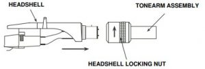
- HEADSHELL:Insert the HEADSHELL into the front end of the TONEARM ASSEMBLY. While holding HEADSHELL firmly into the front end of the tonearm assembly, turn the HEADSHELL LOCKING NUT counter- clockwise to firmly secure the HEADSHELL to TONEARM ASSEMBLY.
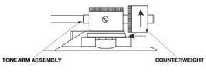
- COUNTERWEIGHT:Locate and remove the tonearm COUNTERWEIGHT from the packaging. Slide COUNTERWEIGHT onto the rear of the TONEARM ASSEMBLY. Turn it lightly and it will screw onto the rear shaft of the tonearm.
Turntable Connections:
Before connecting the unit it is advised that you also consult your current equipment instruction manual.IMPORTANT: Be sure to turn off the equipment before you make changes to the different connections.
- Connect the power cord to an AC outlet.
- Connect the RCA cable to the PHONO input of your AMPLIFIER when you set the PHONO/ LINE switch to PHONO position. You can also use a line input by setting the PHONO/ LINE switch at the rear of the turntable to LINE.
Output terminals Amplifier (Receiver) L (White) L Channel R (Red) R Channel - Connect PC via USB cord.

Turntable Installation:
- Do not place the unit in a location where it will be exposed to direct sunlight or near any type of heating appliance.
- Do not place the unit in a location where there is high humidity or a lot of dust.
- Cartridge may pick up slight sound pressure or vibrations of near by speakers. For best results, do not install this unit too close to speakers.
- Install this unit on a horizontal surface that is stable and vibration free.
- The rubber feet have been specially designed to isolate the unit from excess vibration. The feet may also be used to stabilize the main body horizontally. Adjust the height of the unit by turning the feet in a clockwise or counter-clockwise direction.
Tonearm Balance and Stylus Pressure:
Adjustment of horizontal zero balance and stylus pressure:
- Remove the stylus protective cover, if so equipped. Never touch the stylus tip during the adjustment.
- Lower the TONEARM LEVER.
- Release the tonearm clamp and release the tonearm from the arm rest.
- Set the ANTI-SKATE adjustment to zero.
- Rotate the COUNTERWEIGHT in either direction until the TONEARM is perfectly balanced horizontally(floats freely).
- Return the TONEARM to the arm rest and lock it in place
- Hold the COUNTERWEIGHT stationary with one hand and rotate only the stylus-pressure ring to bring thenumber “0” of the ring into alignment with the center line on the tonearm rear shaft.
- Rotate the COUNTERWEIGHT counterclockwise until the scale value corresponding to the recommendedstylus pressure.
Note: The recommended stylus pressure of the optional cartridge that may have been included with your unitis 2 grams. For all other cartridge systems please refer to the manufactures specification included with the cartridge.
Anti-Skate:
The anti-skate adjustment prevents the TONEARM ASSEMBLY from skipping across the record from the centrifugal force that is caused spinning rotation of the PLATTER. The ANTI-SKATING control knob should be set to the same value as the stylus pressure. For example if your COUNTERWEIGHT is set to 2.5 grams the ANTI-SKATE value should also be set to 2.5.
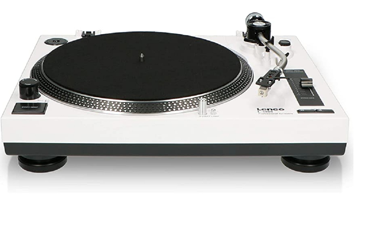
CONTROLS AND FUNCTIONS
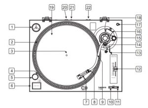
- EP ADAPTERThis adapter allows you to play standard 7″ EP vinyl records with large center holes. Place the adapter on the CENTER SPINDLE 7″ records.
- STROBE INDICATORSThe PLATTER has four rows of indicators. These indicators are used to visually detail various stages of pitch. The indicators are illuminated by the STROBE INDICATOR PILOT LAMP. Each row may appear to stand still at different pitch levels.Note: The use of heavy fluorescent lighting directly above the turntable will defeat the STROBE LAMP PILOT LAMP affect indicator accuracy.
- CENTER SPINDLEThis spindle holds the turntable PLATTER records stable and centered.
- STROBE INDICATOR PILOT LAMPThis is lamp specially designed to pulse a beam of light at the STROBE INDICATORS on the turntable PLATTER. This will give the illusion that indicators are not spinning at certain speeds.
- POWER SWITCHThis is a rotary power switch. To turn main power on turn the switch in a clockwise direction. To turn main power off turn the switch in counter-clockwise direction.
- START/STOP BUTTONThis over sized push button controls platter motion. When the unit is turned on the platter will not automatically begin to spin. Pressing the button once will engage the high torque motor and spin the platter, pressing this again will stop the platter.
- STYLUS HEADSHELLThe included HEADSHELL is used to connect your stylus with the tone arm.
- HEADSHELL LOCKING NUTAfter attaching the headshell to the tonearm, this locking nut will securely hold the headshell to the tonearm.
- S-SHAPED TONE ARMThe tonearm is the mechanism that holds the HEAD- SHELL and stylus allowing it to glide across a record.
- 33-RPM SPEED SELECTOR BUTTONEngaging this button will rotate the platter at 33 revolutions per a minute (RPMs). A function LED will glow when this function is activated.
- 45-RPM SPEED SELECTOR BUTTONSEngaging this button will rotate the platter at 45 RPMs A function LED will glow when this function is activated.
- PITCH ADJUST SLIDERThis slider is used to adjust the playback pitch percentage (platter speed).
- TONEARM LEVERThis lever is used to safely elevates the tone arm above a record surface without endangering a records surface.
- TONEARM CLAMP AND RESTUse this rest to safely hold the tonearm in position during non use and transportation
- ANTI-SKATE CONTROLThe anti-skate applies inward force to the tonearm to prevent outward skipping across the record due to the centrifugal force cause by platter rotation. The anti-skate value should be equally to that of the stylus counterweight pressure.
- COUNTERWEIGHTUse the counterweight to balance the tone arm and to adjust the stylus pressure.
- EXTRA STYLUS HOLDERThis cutout has been designed to safely store an extra stylus headshell.
- COUNTERWEIGHT SCALEThe counterweight scale must face toward the DJ.
- PLATTERThis platter connects directly to the center spindle. The platter and center spindle holds a vinyl record perfectly center. The platter also spins the record at a consistent speed.
- USB SOCKET(USB cable limit within 3m) After connecting the Turntable to the computer via USB, you can record your vinyl to your hard disk using software.
- PHONO/LINE SWITCHThis switch is used to change the mode of PHONO OUTPUT or LINE OUTPUT. When switch is selected as LINE OUTPUT, never connect to a Phono input. With the PRE-AMP switch at ON never connect to a Phono input. Audio will be strongly distorted then and there is a risk that Amplifier and/or speakers will be damaged.
- RCA OUTPUT JACKSThe output is switchable PHONO/LINE output. For example: These jacks are used to send a low voltage “phono” level output signal to a mixers “phono” input jacks. Turntables should be connected to “Phono” inputs on a mixer. The red colored RCA jack represents the right channel input and the white represents the left channel input.
AUDACITY SOFTWARE OVERVIEW
Audacity is free software, licensed under the GNU General Public License (GPL). More information as well as open source code can be found on the CD included or on the web at http://audacity.sourceforge.net/* Please ensure you have installed the software before starting.
Setting up your PC to work with Audacity
- Connect an input source to the unit.
- Connect the USB lead to your computer.
- Install the Audacity recording software.
- Open the Audacity program.
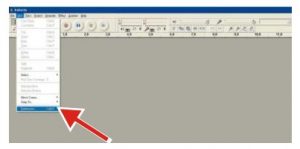
- Select Preference from the Edit tab in the Audacity Menu.
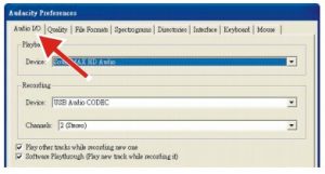
- Select Audio I/O tab at the top left.
- Under Playback, Device, select your internal sound card.
- Under Recording, Device, select USB Audio CODEC.
- Under Recording, Channels, select 2 (Stereo).
- Check the box marked Play other tracks while recording new one.
- Check the box marked Software Playthrough.
Recording Albums with Audacity
- Saving a project
- Audacity writes all the changed and recorded audio to a directory called Projectname_data, which is located right where you saved the project file itself.
- Thus, select Save Project as from your Audacity File tab and choose a location and filename for your project.
- Please note that when you startup Audacity fresh, only the “Save As…” menu option is available.
- How to record
- Set your USB turntable up to play the song or album you want to record.
- Click on the red Record button to begin recording
- Lower tone arm on USB turntable onto album and track you want to record.
- Click on the blue Pause button to pause the recording. Press it again to continue.
- Click on the yellow Stop button.
That’s it. You can now play around with your recording and explore the editing capabilities of Audacity. Remember that you can use the Undo function almost without limits while the project is open NOTE: CD’s cannot be burned directly from the Audacity application. Other CD burning applications should be used.
Remark: For advanced operation, refer instructions inside CD.
SPECIFICATIONS
| GENERAL | |
| Model | Digital USB Turntable |
| Dimensions | 450(W) x 350(D) x 139(H)mm |
| Weigh | 5.36Kg |
| Power supply: | AC 230V~ 50Hz (Netherlands); AC 240V~ 50Hz(U.K.) |
| Power consumption: | 11W |
| Standard test condition: | Ambient Temperature: 20 +/- 2 deg.C Relative Humidity: 65% +/- 5% |
| TURNTABLE SECTION: | |
| Type | 2-speed full manual |
| Motor | 8pole, 2phase,brushless DC motor |
| Driving Method | Direct drive |
| Turntable Platte | 332mm (Aluminum) |
| Speeds | 331 /3 and 45rpm |
| Wow and Flutte | Less than 0.15% WRMS (JIS WTD) with 331 /3 rpm |
| S/N Ratio | More than 55dB (DIN-B) |
| Pitch Controls | +/- 10% |
| Starting Torque | More than 1 kgf.cm |
| Braking System | Electronic brake |
| Starting Time | Less than 1 sec |
| Braking Time | Less than 1 sec |
| Time for Speed Change | Less than 1 sec. from 33 1/3 to 45 rpm. Less than 1 sec. from 45 to 331 /3 rpm |
| High of cue(first track) | 8~10.5 mm |
| Descend of cue | 1~3 sec |
| USB Function | USB rec. Function A/D, D/A 16BIT 44.1KHz or 48KHz USB SELECTABLE Computer interface: USB 1.1 compliant WINDOWS XP, Vista7/8 or MAC OSX |
| TONEARM SECTION | |
| Type | Static balanced straight shaped tone arm with cardan’s suspension |
| Effective Arm Length | 220mm |
| Overhang | 10mm |
| Tracking Error Angle | Less than 3 degree |
| Tracking Force Adjustment Range | 3-4g |
| Applicable Cartridge Weight | 3.5-8.5g |
| Phono Output Level | 1.5~3.6mV at 1KHz 5cm/sec (HP-4005) |
| Line Output Level | 90~216mV at 1KHz 5cm/sec (HP-4005) |
| Anti-skating Range | 0~4g |
| Channel Separation | More than 15 dB |
| Channel Balance | Within 2.5dB at 1KHz |
| EQ AMP | |
| Output | 150mV +/-4dB (IN: 2.5mV 1KHz) |
| RIAA (Frequency Response) | 20Hz~20KHz +1/-3dB (IN: 1.5mV 1KHz ) |
NOTE: Measurements can be carried out between 5 deg.C to 35 deg.C and 45% to 85% relative humidity.
SERVICE AND SUPPORT
- GuaranteeLenco offers service and warranty in accordance with the European law, which means that in case of repairs (both during and after the warranty period) you should contact your local dealer. Important note: It is not possible to send products that need repairs to Lenco directly. Important note: If this unit is opened or accessed by a non-official service center in any way, the warranty expires. This device is not suitable for professional use. In case of professional use, all warranty obligations of the manufacturer will be voided.
- DisclaimerUpdates to Firmware and/or hardware components are made regularly. Therefore some of the instruction, specifications and pictures in this documentation may differ slightly from your particular situation. All items described in this guide for illustration purposes only and may not apply to particular situation. No legal right or entitlements may be obtained from the description made in this manual.
- Disposal of the Old DeviceThis symbol indicates that the relevant electrical product or battery should not be disposed of as general household waste in Europe. To ensure the correct waste treatment of the product and battery, please dispose them in accordance to any applicable local laws of requirement for disposal of electrical equipment or batteries. In so doing, you will help to conserve natural resources and improve standards of environmental protection in treatment and disposal of electrical waste (Waste Electrical and Electronic Equipment Directive).
- CE MarkingProducts with the CE marking comply with the EMC Directive (2014/30/EU) and the Low Voltage Directive (2014/35/EU) issued by the Commission of the European Community. Hereby, Lenco Benelux BV, Thermiekstraat 1a, 6361 HB Nuth, The Netherlands, declares that this product is in compliance with the essential requirements and other relevant provisions of Directive 1999/5/EC.The declaration of conformity may be consulted via [email protected]
- ServiceFor more information and helpdesk support, please visit www.lenco.com Lenco Benelux BV, Thermiekstraat 1a, 6361 HB, The Netherlands.
References
[xyz-ips snippet=”download-snippet”]