
![]()
Lewmar V700 Vertical Windlass65001022 Issue 4Owner’s Manual

Introduction
Dear Customer,Thank you for choosing Lewmar. Lewmar products are world-renowned for their quality, technical innovation, and proven performance. With a Lewmar product, you will be provided with many years of outstanding service.Product supportLewmar products are supported by a worldwide network of distributors and Authorised Service Representatives.If you encounter any difficulties with this product, please contact your national distributor or your local Lewmar dealer.CE ApprovalsFor CE approval certificates contact Lewmar.Important information about this manualThroughout this manual, you will see safety and product damage warnings. You must follow these warnings carefully to avoid possible injury or damage.The type of warnings, what they look like, and how they are used in this manual are explained as follows:
⚠ WARNING!This is a warning against anything which may cause injury to people if the warning is ignored. You are informed about what you must or must not do in order to reduce the risk of injury to yourself and others.
![]() SAFETY SYMBOLWhen you see the safety symbol it means: “Do not…”; “Do not do this”; or “Do not let this happen”.
SAFETY SYMBOLWhen you see the safety symbol it means: “Do not…”; “Do not do this”; or “Do not let this happen”.
Safety Notice
IMPORTANT: Read these notes before continuing.⚠ WARNING!
Windlass general
Classification Societies and Lewmar require that a vessel at anchor must have its chain/rode held by a chain stopper or equivalent strong point at all timesAt all times it is the responsibility of the boat operator to ensure that the anchor and rode are properly stowed for the prevailing sea conditions. This is particularly important with high-speed powerboats because an anchor accidentally deploying while underway can cause considerable damage. An anchor windlass is mounted in the most exposed position on a vessel and is thus subject to severe atmospheric attack resulting in a possibility of corrosion in excess of that experienced with most other items of deck equipment. As the windlass may only be used infrequently, the risk of corrosion is further increased. It is essential that the windlass is regularly examined, operated, and given any necessary maintenance.Please ensure that you thoroughly understand the operation and safety requirements of the windlass before commencing the installation. Only persons who are completely familiar with the controls and those who have been fully made aware of the correct use of the windlass should be allowed to use it. If there is any doubt of how to install or operate this unit please seek advice from a suitably qualified engineer.
- Windlasses used incorrectly could cause harm to equipment or crew.
- Windlasses should be used with care and treated with respect.
- Boating, like many other activities, can be hazardous. Even the correct selection, maintenance, and use of proper equipment cannot eliminate the potential for danger, serious injury, or death.
- Lewmar windlasses are designed and supplied for anchor control in marine applications and are not to be used in conjunction with any other use.
- Keep limbs, fingers, clothing, and hair clear of the windlass, rode, and anchor during operation. Severe bodily harm could result.
- Ensure there are no swimmers or divers nearby when dropping anchor.
- Windlasses must not be used as the sole means of securing the anchor to the bow fitting especially under storm conditions. Anchors should be independently secured to prevent accidental release.
- Classification Societies require that a vessel lying at anchor must have its anchor rope/chain secured to a chain stopper or other suitable independent strong point.
- A windlass should never be used as a mooring bollard, the anchor rode MUST be secured to a mooring cleat, chain stopper or other designated strong point. Using the windlass to secure the road will damage the windlass.
- Do not use windlass for ANY purpose other than deployment and recovery of the anchor.
- The circuit breaker in this product must never be deactivated or otherwise bypassed, it is intended to protect the motor and cables from overheating and damage.
- Always switch off this windlass at the circuit breaker/isolator when not in use.
- It is the unavoidable responsibility of the owner, master or another responsible party to assess the risk of any operation on the vessel.
- Windlass must not be operated whilst under the influence of alcohol or drugs.
Fitting
- This equipment must be installed and operated in accordance with the instructions contained in this manual.Failure to do so could result in poor product performance, personal injury, and/or damage to your boat.
- Consult the boat manufacturer if you have any doubt about the strength or suitability of the mounting location.
Electrical
- Make sure that the boat’s battery power supply has been switched off before starting the installation.
- This product requires installation by a suitably qualified electrical engineer.
Specifications
Gypsy Specifications
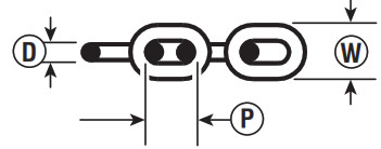
Gypsies fitted to the V700 range of windlasses are ideally suited to handling our factory-made Rope/Chain combination rodes, which consist of rope spliced to a chain tail.Ropes used must be windlass grade, medium lay nylon. Ropes from different manufacturers have wide variations in stretch and consistency in diameter. Therefore, rope and chain from other manufacturers may require some experimentation to determine the optimum size.Should you have difficulty in matching a gypsy to your chain please consult your local agent or our international network of distributors.
 |
 |
 |
 |
|||||
| D (mm) | D (Inch) | P (mm) | P (Inch) | W (mm) | W (Inch) | |||
| 680010246 -7 m – ‘A’Gypsy kit | 12 mm Or)3 Strand and 8 Plait | 6mm DIN 7666 mm ISO 65657 mm DIN 766Yr ACCO ISO GO (GO34: ACCO BBB (3B) | 66777.14 | 0.236 0.236 0.276 0.276 0.281 | 18.5182221.322.1 | 0.728 0.709 0.866 0.840 0.870 | 20.4 21.6 23.9 26.4 25.2 | 0.803 0.850 0.937 0.962 0.992 |
V700 Specifications
| MOTORSUPPLY | MOTORPOWER | MAX. PULL | MAX. LITESPEED | MAX. LITESPEED | TYPICAL LINE SPEED | NORMAL CURRENTDRAW | CIRCUITBREAKER | WEIGHT | |||||
| Voltage | Watt | kg | lb | kg | lb | m/min | ft/min | m/min | ft/min | Amp | Amp | kg | lb |
| 12 | 320 | 320 | 700 | 79 | 175 | 25 | 82 | 15 | 50 | 45 | 35 | 6.5 | 14 |
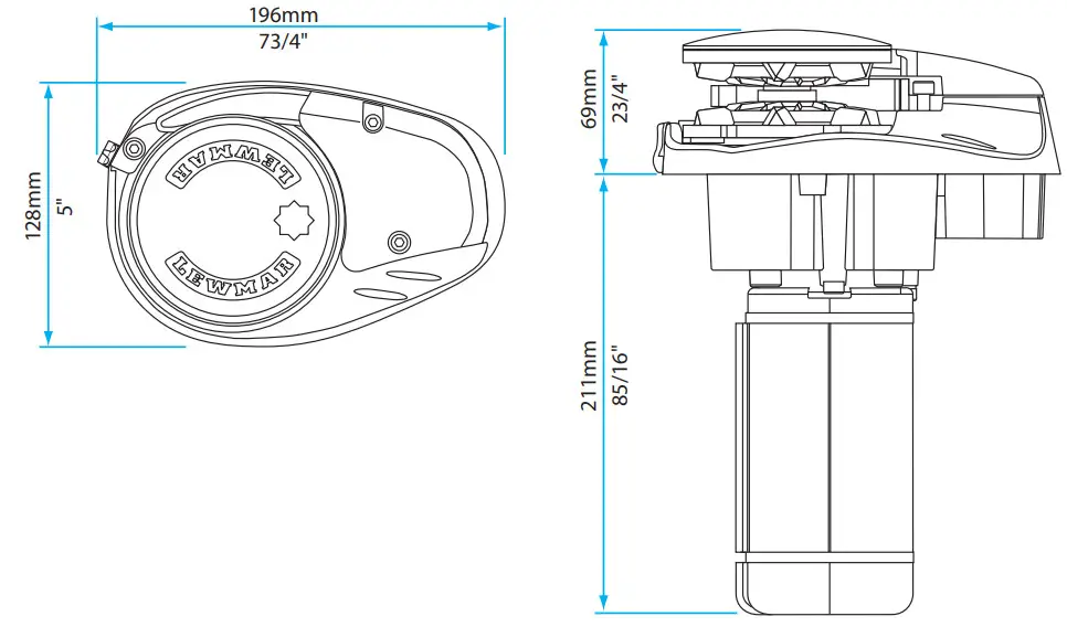
Dimensions Diagram
Installation
Basic requirements
Each installation requires the following tools:Windlass InstallationAn appropriate marine sealant and the following:
- 9.5 mm (3/8”) Drill
- 65 mm (2 1/2”) Hole Saw
- 115 mm (4 1/2”) Hole Saw
- Hack saw
Wiring Installation
- Crimping Pliers / Wire Stripper
- Suitable electrical cable and crimp terminals
Accessories
Use only genuine Lewmar parts and accessories to ensure top performance and eliminate the risk of voiding your warranty.
Fitting the windlass to the deck
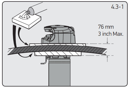
- If the deck is not fl at, a suitable mounting pad may be required to take up camber or sheer. Decks that are thin, or of foam or balsa laminate construction, will require reinforcement in order to spread the loads that will be applied to the deck while the windlass is in use. The standard 8 mm (5/16”) threaded mounting studs supplied suit deck and packing thickness of up to 76 mm (3”). These are adequate for most installations.

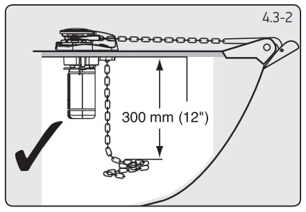
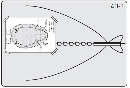
- Place the windlass on the deck and decide upon a position for it with reference to the vessel’s bow roller (Fig. 4.3-2) and the chain locker below. Rode lead from the roller should ideally be fed horizontally back to the top of the gypsy and along its centerline (Fig. 4.3-3).There must be sufficient vertical fall for the chain or rope, even with a full locker, to draw the rode from the gypsy when hauling in.
- Place the mounting template on the deck or mounting pad in the desired position for the windlass and hold it in place using adhesive tape.NOTE: Check the scale of the template matches the winch.
- Using a 10 mm (3/8”) diameter drill, make the three holes for the mounting studs. With a 65 mm (21/2”) diameter hole saw, make the hole for the rod to pass through with a 115 mm (4 1/2”) diameter hole saw, make a hole for the motor gearbox to pass through.When all the holes have been made, remove the template. To help avoid water absorption by the deck, apply an appropriate marine sealant to the freshly cut hole edges.
- Fully screw the three mounting studs into the base of the windlass. This can be done, quite simply, using the multi-tool wrench supplied. Screw the studs into the base finger tight, with the flats towards the base as shown (Fig 4.3-5).
- Next, using the wrench on the flats, tighten the studs until they bottom out in their holes. Do this to each of the studs in turn.7. Place the base mat in position on the deck, optionally, apply a suitable sealant to the base of the windlass, any mounting pad or around the studs.As a rule of thumb, if the flats on the studs are visible below the deck, the deck and/or any packing is likely to be too thin to offer adequate support when the windlass is under load.NOTE: If using silicone or another rubbery type sealant, it is advisable to allow curing of the sealant before final tightening of the mounting nuts. Trim the studs back to 6 mm (1/4”) below the fully tightened nuts.

 7. Place the base mat in position on the deck, optionally, apply a suitable sealant to the base of the windlass, any mounting pad or around the studs.As a rule of thumb, if the flats on the studs are visible below the deck, the deck and/or any packing is likely to be too thin to offer adequate support when the windlass is under load.NOTE: If using silicone or another rubbery type sealant, it is advisable to allow curing of the sealant before final tightening of the mounting nuts. Trim the studs back to 6 mm (1/4”) below the fully tightened nuts.
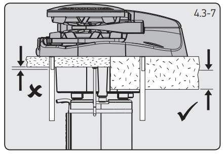
Electrical wiring
Electric cable selection
Lewmar recommends the installer source and installs cable that meets the requirements of the standards and regulations relevant to the installation and codes of practice. The cable table gives recommended cable sizes based on the total length of cable required, from the battery, following the route of the cables.Windlass performance is directly related to cable size and length. The voltage drop over the complete wiring run must not exceed 10%.DO NOT confuse cable length with the length of the vessel
![]() DO NOT confuse cable length with the length of the vessel
DO NOT confuse cable length with the length of the vessel
| CABLE SIZING FOR LENGTH OF CABLE RUN | |||||
| 0 – 10 m | 0 – 33 ft | 11 – 18 m | 34 – 60 ft | 19 – 24 m | 61 – 80 ft |
| 10 mm2 | 8 AWG | 16 mm2 | 6 AWG | 25 mm2 | 4 AWG |
Wiring
Plan the installation to suit the controls and give the operator a full view of the windlass. The wiring system should be of the fully insulated type, which avoids possible electrolytic corrosion problems. We recommend the use of type III stranded, tinned copper wire with copper crimp terminals. Most modern installations are negative returns (negative ground) but polarity should be checked.Overload protection, in the form of the circuit breaker/fuse supplied, must be built into the windlass wiring circuit.⚠ WARNING!NOTE: The circuit breaker should be positioned close to the battery in a dry, readily accessible place. The breaker must be manually reset should an overload occur that causes it to trip to the off position. If you are not sure you understand these guidelines, seek professional help. Ensure that the installation complies with USCG, ABYC, NMMA, or other local regulations.
Control switch installation
Follow the mounting instructions supplied with the switch.NOTE: In a multi-station installation all switches must be wired in a parallel circuit.
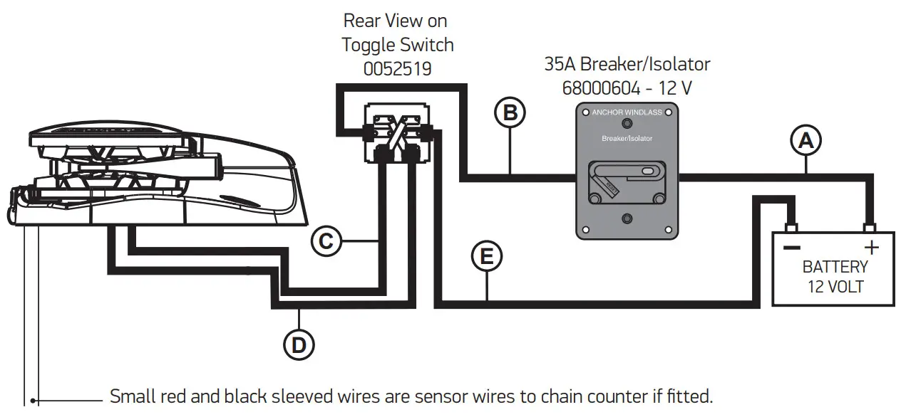
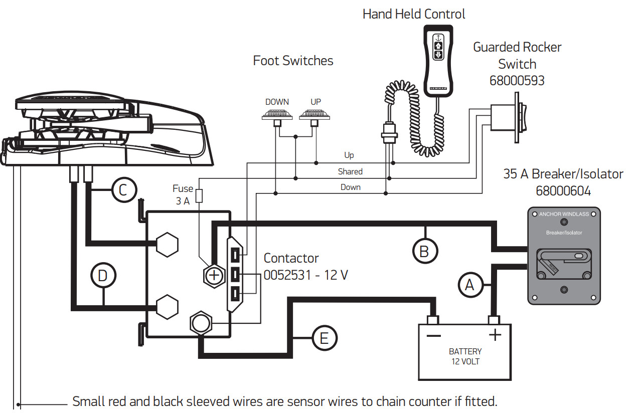
V700 Wiring diagram (toggle switch)
Choice of cable thickness depends on total cable length:A + B + C + D + E =Battery to the windlass, windlass to the battery.
V700 Wiring diagram (contactor)
Operation
Operating tips
Vessels at anchor will snub on the rode and this can cause slippage or apply excessive loads to the windlass.
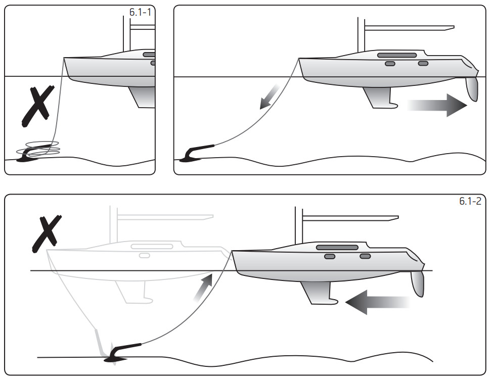
1. When anchoring, power rode out allowing the vessel to take up stern away preventing the rode tangling with an anchor. Use this method for mooring stern first to a jetty.2. To aid recovery, under power, move vessel towards anchor but not over and beyond, as this can cause damage to the topside.
- As the anchor approaches the vessel, use careful adjustments of controls to avoid damaging the vessel.
- Scope: As a guide, it is recommended that the depth of chain to rope is 7 to 1 at anchor.
![]() The rode should be secured directly to a bollard, Sampson post, or cleat and chain secured by a chain stopper.
The rode should be secured directly to a bollard, Sampson post, or cleat and chain secured by a chain stopper.![]() When retrieving anchors do not overload or stall in the windlass.
When retrieving anchors do not overload or stall in the windlass.
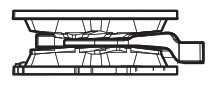
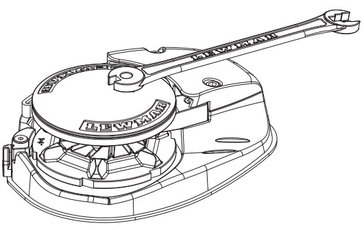
Use of clutch
To tighten the clutch – using the clutch lever supplied, rotate the gypsy drive cap (31) clockwise, this will grip the gypsy, effectively locking it to the windlass geartrain.To slacken the clutch – turn the gypsy drive cap anti-clockwise, this will free the gypsy allowing it to turn independently of the windlass geartrain.⚠ Always remove the handle after use.
Letting go under gravity
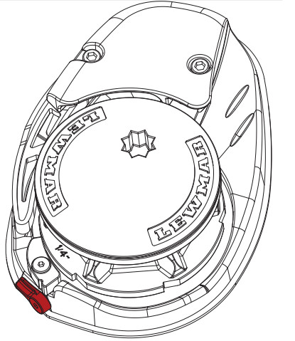
⚠ Always check the fallsafe pawl (32) is disengaged from the gypsy and held clear of it by the fallsafe lever (34).Insert the clutch lever into the gypsy drive cap (31) and turn it clockwise to ensure that the clutch is tight. Release any independent anchor locks. If it is safe to do so, pull back on the clutch lever until the anchor and rode begin to payout. Control the rate of descent of the anchor by pushing the clutch lever forwards. When sufficient rode has been paid out, fully tighten the gypsy drive cap once again.
![]() For maximum safety and to prevent damage, the fallsafe pawl MUST NOT be left to take the entire force from the anchor rode while at anchor. The rode should be made fast directly to a bollard, Sampson post, or cleat.
For maximum safety and to prevent damage, the fallsafe pawl MUST NOT be left to take the entire force from the anchor rode while at anchor. The rode should be made fast directly to a bollard, Sampson post, or cleat.
Letting go under power
Release any independent anchor locks.If it is safe to do so, let go under power by operating a ‘Down’ control. Release the control when sufficient rode has been paid out.
Lying to anchor safely
Vessels at anchor will snub on the rode and this can cause slippage or apply excessive loads to the windlass.
Hauling in
Untie the bridle or replace the rode in the gypsy.If it is safe to do so, operate an ‘Up’ control.The fallsafe pawl (32) does not need to be disengaged during retrieval as it will act as a ratchet. When the anchor has been retrieved and is stowed in the bow roller, the fallsafe pawl should be left engaged in the gypsy to prevent accidental deployment of the anchor whilst underway.REMEMBER – The fallsafe pawl DOES need to be disengaged from the gypsy before the anchor can be let go again.Having retrieved the anchor, ensure it is independently secured to prevent its accidental release.
Manual recovery
Insert clutch lever supplied into gypsy drive cap (31) and turn clockwise to haul in the anchor.
Operating tips
When anchoring, it is best to power the rode out, allowing the vessel to take up stern way before the full scope is let out. This helps prevent the rode from becoming tangled on top of your anchor on the seabed.To aid anchor recovery, we recommend that the vessel’s engine be used to assist by moving the vessel towards the anchor. We do not recommend that the vessel be motored over and beyond the anchor, as this can cause the rode to damage your topsides.As the anchor approaches the stemhead, the last few feet of rode should be inched in by judicious use of controls to avoid damage to the vessel.Having retrieved the anchor, ensure the fallsafe pawl is engaged in the gypsy to lock it and prevent accidental deployment of the anchor whilst underway.When mooring stern-to, at a suitable distance from the jetty, deploy the anchor to prevent the bow from swinging. Gently pay out the rode under the influence of the stern way of the vessel as it approaches the jetty.Make fast your vessel with warps from the stern.
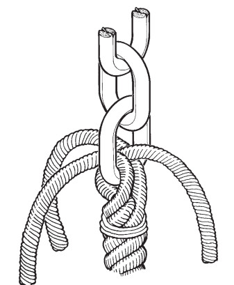
Joining rope to chain
When splicing rope to chain, select a length of chain that will avoid having the splice positioned in the gypsy when the anchor comes over the stemhead. Furthermore, ensure that the splice is no tighter than the rope.A hard splice is not desired.
- With whipping twine or similar, seize your rope 200 mm (8”) from the rope’s end and unlay the strands.
- Pass one strand through the chain link from one side and the other two strands from the opposite side. Remove seizing and complete a back splice in the normal manner for four full tucks.
- With a hot knife pare down the three strands by one-half of their diameter and continue with two further tucks.
- With a hot knife, carefully melt the ends back into the line.Because of wide variations in rope type and construction, some experimentation may be required.
- Whip the line with permanent whipping at the beginning of the taper.
- The method of joining illustrated is designed to minimize chafe between the rope and chain but as a matter of prudent seamanship, the splice should be checked regularly and remade if there is any evidence of wear.
Servicing
⚠ WARNING! Ensure rode is adequately secured to an independent strong point.⚠ WARNING! Isolate the windlass using a circuit breaker/isolator.
Servicing schedule
Regularly:
- Wash down the windlass using freshwater.
- Examine all electrical connections for corrosion, clean, and lightly grease.
- Check anchor locker drain to avoid water damage to motor/gearbox.
- If the anchor locker fills with water, check the motor is dry and free of rust.
- Check anchor rode splice for wear.
- Check gypsy as it is a high wear item and will last longer if properly used. When re-assembling the cone and gypsy, add a small smear of grease to the contact surfaces.
- Check mounting studs after the first two or three recoveries and regularly thereafter.
Annually:
- Check electric cables for damage. Repair/renew as required.
- Strip the above deck components, clean and lightly grease.
- Check motor/gearbox for corrosion, clean, and repaint with a suitable marine-grade oil-based enamel paint.
- Remove electric motor cover and blow dust away from brushes using a foot pump or similar taking care not to breathe any dust.
Gypsy replacement/service
- Remove the Gypsy Drive Cap (31), anti-clockwise using the clutch operating lever.
- Withdraw the Drive washer (21)
- Remove the Socket Head Cap Screw (40) that retains the Strapper using a (5mm) Allen Wrench.
- Pull the Control Arm (30) back to clear the Gypsy
- Remove the Gypsy Assembly (37).
- To replace the Gypsy, reverse the above procedure.
Control arm replacement
- This should be carried out with the Gypsy (37) removed as detailed above.
- To remove the Control Arm (30): unscrew the Control Arm Shoulder Screw (24) using a (4 mm) Allen Wrench and remove the screw.
- Remove the Control Arm (30) and Torsion (12) Spring from the base plate.
- To replace the Control Arm, reverse the above procedure.
Main shaft lubrication
Note: The gear train and its bearings have been lubricated for you with SFG 100 grease and should require no regular attention. SFG is a white synthetic grease containing PTFE. Use grease of a similar specification throughout.
- It is recommended that the external Drive Shaft components be stripped, cleaned, and re-greased at least annually.
- To do this, the Gypsy Assembly (37) should be removed as detailed above.
- Inspect the Main Shaft (20) and Gypsy (37) for damage before reassembly.
Fall safe pawl replacement
- This should be carried out with the Gypsy (37) removed as detailed above.
- Turn the fall safe lever (34) so it is horizontal.
- Remove fall safe shoulder screw (35) using Allen wrench.
- Liftoff fall safe pawl (32). Remove fail-safe spring (36).
- Replace the new part by reversing the above procedure.
Fall safe lever replacement
- Turn fall safe lever (34) so it is horizontal.
- Remove socket screw (6) using Allen wrench.
- Remove fall safe lever (34).
- To refit use thread lock on the socket screw (6).
- Screw down screw (6) finger tight and leave to cure before operating fall safe lever (34).
Troubleshooting
Electric windlass
- Anchor rode pays out independently while windlass is not in use.This problem is a result of not securing the anchor rode combined with the gypsy drive cap being slack. Tighten the gypsy drive cap using the winch handle and always secure the anchor rode independently of the windlass when not in use.
- Failure to operate or sluggish operation.• The majority of these problems are electrical in nature. It is essential that the proper voltage be maintained. The proper voltage on a 12 Volt system is 13.5 Volts (24 Volt system is 26.5 Volts), constant low voltage will damage the motor.• Ensure electrical cable size is large enough to handle the current draw and keep voltage drop within acceptable limits.• Check control switches, connections, battery condition, isolator switch, fuse, and motor for operation failure.
| Failure to Operate Troubleshoot Chart: Reversing Toggle Control Switch (Part No. 0052519) | |
| Is there voltage at the input terminal (positive) to the control switch? | If no voltage is present, the battery isolation switch is OFF, the breaker is tripped or a fuse has blown. The battery may also have been dead or disconnected. |
| YES ▼ | NO ▶ |
| Check voltage at the output terminals of the control switch with the switch on forward then reverse.Is there voltage at either output terminal for forward then reverse.? | The control switch is defective. |
| YES ▼ | NO ▶ |
| Replace motor. | |
| Sluggish Operation Troubleshoot Chart | |
| Is windlass overloaded? | Ease the load and ensure the battery is well charged. |
| YES ▼ | NO ▶ |
| Check the voltage across the motor leads with the windlass on. (Proper voltage is 13.5 V. Constant low voltage will destroy the motor).Is the voltage low? (Below 11.0 V on a 12 V system). | There is a severe voltage drop in the circuit.Check for undersized cables, poor connections, or corroded connections. Also check for resistance across the battery, isolation switch, or solenoid. (Feel them see if they are heating up). |
| YES ▼ | NO ▶ |
| Is the voltage correct?(Above 11.0 V and anchor is not fouled). | |
| YES ▶ | The motor is defective. Replace the motor. |
Part list
 report this ad
Service kits
| KIT NO. | KIT DESCRIPTION | ITEMS INCLUDED (QTY) |
| 66000099 | Clutch Lever | Clutch Lever (1) |
| 66000600 | Control Arm Kit | 12(1).24(1).30(1) |
| 66000601 | Gypsy Cap Kit | 21(1). 31(1) |
| 66000602 | Mounting Kit 5116″ USA | 18(1).26a(1), 33(1), 38(1) |
| 66000603 | Gypsy RC 1/4″G4 82 7mm Kit | 37a(1). 40(1) |
| 66000604 | Gypsy RC 6 mm DIN 76616t | 37b(1).40(1) |
| 66000605 | Mounting Kit Metric | 18(1). 26b0). 33(1). 38(1) |
| 66000606 | Chain Pipe Cover | 29(1). 40(2) |
| 66000607 | Fall Safe Kit | 60). 320). 34(1). 350). 360) |
| 66000608 | Bearing/Seal Kit | 3(1). 4(1).5(1). 7(1). 13(2). 16(1). 17(1). 19(1) |
| 66000609 | Driveshaft Kit | 1(3). 8(1). 110). 16(1), 20(1), 21(1) |
| 66000610 | Motor Kit | 6(3).9(2). 16(1). 25(1).27(1) |
| 66000611 | Gearcase Complete | 2(3). 30). 130). 14(1). 160). 170). 230). 41(3) |
| 66000612 | Gear Set | 1(3).8(1). 10(1). 15(1). 16(1).22(1) |
| 66000613 | Compound Gear Assy. | 16(1). 22(1) |
| 66000614 | 1st Compound Gear | 15(1). 16(1) |
| 66000615 | Magnet (E0 Sensor Kit | 39(1) |
Parts list key
| ITEM | DESCRIPTION |
| 1 | SS Roller |
| 2 | M6 Spring Washer |
| 3 | Needle Roller Bearing |
| 4 | Roller Clutch |
| 5 | Ball Bearing |
| 6 | M5 x 12 CSK Socket Screw |
| 7 | Internal Circlip |
| 8 | External Circlip |
| 9 | Black Nylon Cable Tie 200 mm |
| 10 | Mainshaft Gear 48 Teeth |
| 11 | Mainshaft Spacer |
| 12 | Control Arm Torsion Spring |
| 13 | Needle Roller Bearing |
| 14 | Gearcase |
| 15 | 1st Compound Gear |
| 16 | Gear Case Gasket |
| 17 | Needle Roller Bearing |
| 18 | Clamping Plate |
| 19 | Wiper Seal |
| 20 | Mainshaft |
| 21 | Drive Washer |
| 22 | 2nd Compound Gear Assy. |
| 23 | Bush 6 x 12 |
| 24 | Control Arm Shoulder Screw |
| 25 | Motor Cover |
| 26a | Mounting Studs 5/16″ (USA) |
| 26b | Mounting Studs Metric M8 |
| 27 | IP67 Motor, 320 W |
| 28 | Baseplate |
| 29 | Chain pipe Cover |
| 30 | Control Arm |
| 31 | Gypsy Drive Cap |
| 32 | Fall Safe Pawl |
| 33 | Chain Pipe Sleeve |
| 34 | Fall Safe Lever |
| 35 | Fall Safe Shoulder Screw |
| 36 | Fall Safe Spring |
| 37a | Gypsy RC 1/4″G4 & 7 mm DIN766 |
| 37b | Gypsy RC 6 mm DIN 766 |
| 38 | Basement |
| 39 | Magnet D Sensor Kit |
| 40 | M6 x 20 mm SKT HD Cap Screw |
| 41 | M6 x 60 mm SHT HD Cap Screw |
[xyz-ips snippet=”download-snippet”]