![]() Lewmar 3 & 5 Button Wireless Remote Control66300103 Issue 1
Lewmar 3 & 5 Button Wireless Remote Control66300103 Issue 1

Owner’s Installation![]() WARNING! This manual forms part of the product and MUST BE kept with boat documents.To the best of our knowledge, the information in this manual was correct when it went to press. However, Lewmar cannot accept liability for any inaccuracies or omissions it may contain. In addition, our policy of continuous product improvement may change specifications without notice. As a result, Lewmar cannot accept liability for any differences between the product and the manual.
WARNING! This manual forms part of the product and MUST BE kept with boat documents.To the best of our knowledge, the information in this manual was correct when it went to press. However, Lewmar cannot accept liability for any inaccuracies or omissions it may contain. In addition, our policy of continuous product improvement may change specifications without notice. As a result, Lewmar cannot accept liability for any differences between the product and the manual.
Introduction
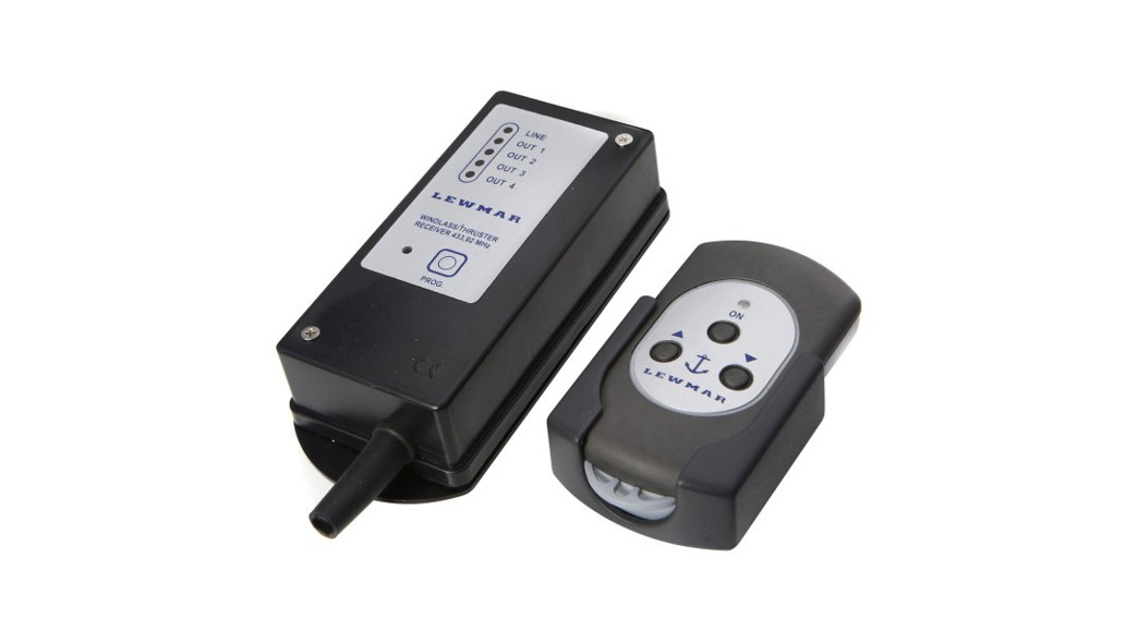
Thank you for purchasing a Lewmar Wireless remote control kit
- Simple to Install in new installations and retro-fit.
- Compatible with all Windlasses operated by a contractor.
- Compatible with TT Thruster installations.
- Watertight key-fob Transmitter unit Control from multiple transmitter units.
1.1 Product supportLewmar products are supported by a worldwide network of distributors and Authorised Service Representatives. If you encounter any difficulties with this product, please contact your national distributor or your local Lewmar dealer.1.2 CE & FCC ApprovalsFor CE approval certificates contact Lewmar. This device complies with part 15 of the FCC Rules. Operation is subject to the following two conditions:
- This device may not cause harmful interference.
- This device must accept any interference received, including interference that may cause undesired operation.
1.3 Important information about this manualThroughout this manual, you will see safety and product damage warnings. You must follow these warnings carefully to avoid possible injury or damage. The type of warnings, what they look like, and how they are used in this manual are explained as follows:![]() WARNING! This is a warning against anything which may cause injury to people if the warning is ignored. You are informed about what you must or must not do in order to reduce the risk of injury to yourself and others.
WARNING! This is a warning against anything which may cause injury to people if the warning is ignored. You are informed about what you must or must not do in order to reduce the risk of injury to yourself and others.![]() SAFETY SYMBOL. When you see the safety symbol it means: “Do not…”; “Do not do this”; or “Do not let this happen”.
SAFETY SYMBOL. When you see the safety symbol it means: “Do not…”; “Do not do this”; or “Do not let this happen”.
Safety Notices
![]() WARNING!IMPORTANT: Read these notes before continuing.2.1 Wireless remote generalPlease ensure that you thoroughly understand the operation and safety requirements of the wireless remote control system and the units operated before commencing the installation. Windlasses and Thrusters are powerful devices. Accidental or improper operation can cause personal injury or damage to the boat and property.Please read the following precautions to limit the risk of accidental operation.
WARNING!IMPORTANT: Read these notes before continuing.2.1 Wireless remote generalPlease ensure that you thoroughly understand the operation and safety requirements of the wireless remote control system and the units operated before commencing the installation. Windlasses and Thrusters are powerful devices. Accidental or improper operation can cause personal injury or damage to the boat and property.Please read the following precautions to limit the risk of accidental operation.
- The operator should always have a clear view of the windlass when operating.
- Ensure all people on board are at a safe distance from the Windlass, rode, and anchor before operating.
- The wireless transmitter should be kept in its cradle or another protected place when not in use. The transmitter should never be placed in a pocket or other location where accidental unintended operation is possible.
- Windlass and Thruster system should always be switched off at the breaker panel or isolator when not in use to prevent unintended operation.
- Do not operate if under the influence of drugs or alcohol. · Consult your Windlass and Thruster manual for other operational precautions.
![]() DO NOT use the wireless remote control system for any other purpose than those described in this manual.
DO NOT use the wireless remote control system for any other purpose than those described in this manual.
Installation
3.1 Basic requirementsEach installation requires:TRANSMITTER AND RECEIVERThe following tools:
- Power drill with 2mm (5/64″) drill
- Pozidriv screwdriver
WIRING
- Crimping Pliers/Wire Stripper
- Suitable electrical cable and crimp terminals
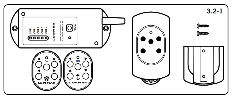
3.2 Components
 |
 |
- NOTE: Wireless remote will only work with Lewmar products fitted with a contractor.
1. 68000968 – 5 button wireless remote kit
- 4 channel radio control unit supplied pre-programmed to the receiver unit.
- Transmitter supplied with 2 x 1.5V AAA alkaline batteries.
- Adhesive labels for thruster or windlass function.
- Support kit for the transmitter.
- 2 x 3.5 x 13mm screws.
- Instruction manual.
2. 68000967 – 3 button wireless remote kit
- 2 channel radio control unit supplied pre-programmed to the receiver unit.
- Transmitter supplied with 2 x 1.5V AAA alkaline batteries.
- Support kit for the transmitter.
- 2 x 3.5 x 13mm screws.
- Instruction manual.
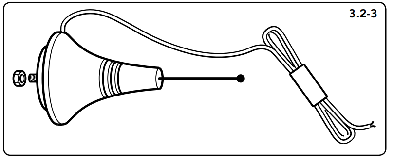
3. Remote antenna kit
- 68000969 – Antenna with 10m cable.Spare Transmitters
- 3 buttons – 68001005
- 5 buttons – 68001006
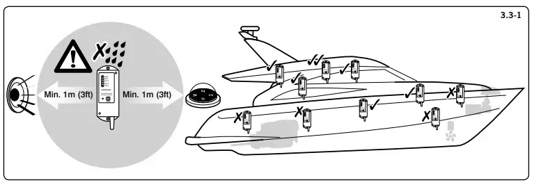
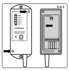
3.3 Locating receiver![]() WARNING! Disconnect or isolatethe battery before installation.In both windlass and thruster installations, it is recommended that the wireless control system is not the sole control medium foreach product. The windlass should also have deck/rocker switches installed as per the windlass installation manual. The thrustershould also have at least one TT control panel installed as per the Thruster installation manual.
WARNING! Disconnect or isolatethe battery before installation.In both windlass and thruster installations, it is recommended that the wireless control system is not the sole control medium foreach product. The windlass should also have deck/rocker switches installed as per the windlass installation manual. The thrustershould also have at least one TT control panel installed as per the Thruster installation manual.
- Position the receiver with the following precautions:• In a dry, accessible location.• As high up in the vessel as possible.• As far as possible from large metal masses, electrical motors, or windlass.• At least 1m (3ft) away from electrical wiring, navigational and radio equipment.
 |
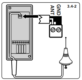 |
3.4 Connecting the optional external antenna
- Position the antenna in a suitable location on the vessel with the same precautions as the receiver.1. Open the receiver and remove the internal antenna from the terminal board.2. Run the cable in the same space as the internal antenna and connect to the terminal box:
- Cable radio signal wire to ANT.
- Cable shield to GND.
Electrical Wiring
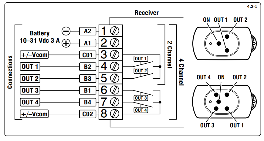
4.1 Electric cable selectionLewmar recommends the installer source and installs cable that meets the requirements of the standards and regulations relevant to the installation and codes of practice.4.2 Receiver wiring diagram![]() WARNING! Connect only to a DC power supply
WARNING! Connect only to a DC power supply
- Figure 4.2-1 shows a typical installation wiring diagram.
- The receiver is supplied with 2 or 4 relay outputs with one or two common contacts. Common contact must be connected to the positive or negative pole, according to the polarity of the load connected.•To avoid an overload due to a short circuit a 3A fuse must be fitted.
| Receiver /Transmitter | Supply | Frequency | ProtectionRating | OperatingTemperature | Maximum Load10 – 30 V DC |
| 2 & 4 Channel | 10 to 30 Vdc | 433.92 MHz | IP65 | 0 to +70 °C32 to 158 °F | 3:00 AM |
| 6800100568001006 | 2 x 1.5 V AAAAlkaline | 433.92 MHz | IP66 | – |
Operation
![]() WARNING! Operate equipment only when in direct sight.
WARNING! Operate equipment only when in direct sight.![]() WARNING! Trapping, crushing, or entanglement danger whilst operating windlass manually or under power.5.1 Transmitter function
WARNING! Trapping, crushing, or entanglement danger whilst operating windlass manually or under power.5.1 Transmitter function
- NOTE: Transmitters supplied in the kit are already pre-programmed to the receivers.
- Press the ON button for 2 seconds, the LED will light. Release the button and the LED will blink slowly indicating the transmitter is operational but not transmitting a signal.
- When an operation button is pressed the LED will blink quickly indicating it is sending a signal. When released the LED will blink slowly.
- Transferring from one operating button to the opposite (UP to DOWN or LEFT to RIGHT) has a standard 1.5-second delay. Simultaneous use of NONopposite buttons is allowed (4 channel unit only).
- The transmitter will switch off automatically after 2 minutes if not used.
5.2 Receiver function
- When power is applied, the green LINE LED lights up. After 1 second the red PROG LED lights up as well.
- The red PROG LED keeps lit for 15 seconds. This is the time the receiver is ready to accept a new transmitter code and memorize it.
- When an operation button on the transmitter is pressed a yellow OUT LED on the receiver will light up corresponding to the action requested.
 report this ad
5.3 Programming additional transmitters to the receiver•To add a new transmitter to a device you already use follow these steps:
- Apply power to the receiver, press the PROG button until the red LED lights and release, you will have 15 seconds to program to receiver
- Press the new transmitter ON button for 2 seconds until the LED blinks.
- Press the bottom left (OUT 1) button and hold.
- Press the receiver PROG button.
- Release the button on the transmitter.
- If the code has been accepted the receiver’s red PROG LED will blink 4 times and then turns off to confirm programming.
- Check the new transmitter functions correctly.
•It is possible to store up to 5 transmitters at the same time, when the memory is full any additional transmitters will overwrite the first code the receiver had programmed in its memory.5.4 Battery replacement![]() WARNING! Isolate the windlass/thruster using a circuit breaker/isolator.
WARNING! Isolate the windlass/thruster using a circuit breaker/isolator.
- Unscrew the 6 screws on the transmitter’s rear cover and carefully remove them.
- Replace batteries with 2 x 1.5V AAA Alkaline batteries taking care not to drop the circuit board and batteries. Check the battery’s polarity match the + and markings on the board.
- Reposition the rear cover and screw tight taking care, not to over tighten the screws.
5.5 TroubleshootingWindlass/thruster not working.
- Is the transmitter switched?
- Does the transmitter blink when the operation button is pressed? If not change the batteries.
- Move the transmitter closer to the receiver.
- Check installation.
- Follow troubleshooting instructions in the windlass/thruster manual.
Discover other anchors & docking on our website.
[xyz-ips snippet=”download-snippet”]