INSTALLATIONInstallation Overview
Please read the following installation instructions first after purchasing this product or transporting it to another location.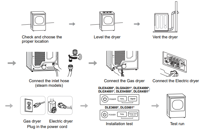
Product Specifications
The appearance and specifications listed in this manual may vary due to constant product improvements.
| Dryer Models | DLE3600*,OLG3601* | DLEX4000*,DLGX4001* | DLEX4200*,DLGX4201* | DLEX4500t, DLGX4501* |
| Description | Non-steam Dryer | Steam Dryer | Steam Dryer | |
| Electrical requirements | Please refer to the rating label for detailed information. | |||
| Gas requirements | NG: 4 – 10.5-inch (10.2 – 26.7 cm) WC LP: 8 – 13-inch (20.4 – 33.1 cm) WC | |||
| Dimensions | 27″ (W) X 301/8″ (D) X 39″ (H), 51 3/8″ (D with door open)68.6 cm (W) X 76.5 cm (D) X 99 an (H), 130.5 cm (D with door open) | 27″ (VV) X 30′ (D) X 39″ (H), 51′ (D with door open)68.6 an (W) X 76.1 an (D) X 99 cm (H), 129.7 cm (D with door open) | ||
| Net weight | Gas : 136.03 lb (61.7kg) – 139.34 lb (63.2kg) Electric :121.9 lb (55.3kg) – 125.3 lb (56.8kg) | Gas :140.4 lb (63.7 kg) Electric : 133.4 lb (60.5 kg) | ||
| Drying capacity | Steam Cyde | – | I IEC 7.4 cull (8 lb/3.6 kg) | |
| Normal Cycle | 1EC 7.4 cu.ft. (22.5 lb/10.2 kg) |
NOTEModel numbers can be found on the cabinet inside the door.
Installation Location Requirements
![]() WARNING
WARNING
- Read all installation instructions completely before installing and operating your dryer. It is important that you review this entire manual before installing and using your dryer. Detailed instructions concerning electrical connections, gas connections and exhaust requirements are provided on the following pages.
![]() WARNINGTo reduce the risk of serious injury or death, follow basic precautions, including the following:
WARNINGTo reduce the risk of serious injury or death, follow basic precautions, including the following:
- Use long-sleeved gloves and safety glasses.
- The appliance is heavy. Two or more people are required when installing the dryer.
The installation requires:
- A location that allows for proper exhaust installation. A gas dryer must be exhausted from the outdoors. See Venting the Dryer.
- A grounded electrical outlet is located within 2 ft. (61 cm) of either side of the dryer. See Connecting Electric Dryers.
- A sturdy floor to support the total dryer weight of 200 lb (90.7 kg). The combined weight of a companion appliance should also be considered.
- No other fuel-burning appliance can be installed in the same closet as a dryer.
- Additional clearances might be required for wall, door, and floor moldings.
- Companion appliance spacing should also be considered.
NOTE
- The floor must be level, with a maximum slope of 1 inch (2.5 cm) under the entire dryer. Clothes may not tumble properly, and automatic sensor cycles may not operate correctly if the dryer is not level.
- For garage installation, you will need to place the dryer at least 18 inches (45.7 cm) above the floor. The standard pedestal height is 15 inches (38 cm). You will need 18 inches (45.7 cm) from the garage floor to the bottom of the dryer.
- Do not operate your dryer at temperatures below 45 °F (7 °C). At lower temperatures, the dryer might not shut off at the end of an automatic cycle. This can result in longer drying times.
- The dryer must not be installed or stored in an area where it will be exposed to water and/or weather.
- Check code requirements that limit, or do not permit, installation of the dryer in garages, closets, mobile homes, or sleeping quarters. Contact your local building inspector.
Clearances![]()
Installation Spacing for Recessed Area or Closet Installation
The following clearances are recommended for this dryer. This dryer has been tested for clearances of 1 inch (2.5 cm) on the sides and rear. Recommended clearances should be considered for the following reasons:
- Additional clearances should be considered for ease of installation and servicing.
- Additional clearances should be considered on all sides of the dryer to reduce noise transfer. For closet installation, with a door, minimum ventilation openings in the top and bottom of the door are required. Louvered doors with equivalent ventilation openings are acceptable.
- Closet Ventilation RequirementsClosets with doors must have both an upper and lower vent to prevent heat and moisture buildup in the closet.One upper vent opening with a minimum opening of 48 sq. in. (310 cm2) must be installed no lower than 6 feet above the floor. One lower vent opening with a minimum opening of 24 sq. in. (155 cm2) must be installed no more than one foot above the floor. Install vent grilles in the door or cut down the door at the top and bottom to form openings. Louvered doors with equivalent ventilation openings are also acceptable.NOTE
- There should be at least a little space around the dryer (or any other appliance) to eliminate the transfer of vibration from one appliance to another. If there is enough vibration, it could cause appliances to make noise or come into contact, causing paint damage and further increasing noise.
Installation Spacing for Recessed Area or Closet, with Stacked Washer and Dryer
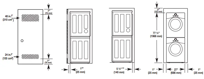
* Required spacing** For side or bottom venting, 2-inch (5.1 cm) of spacing is allowed.Installation Spacing for CabinetFor cabinet installation with a door, minimum ventilation openings in the top of the cabinet are required.* Required spacing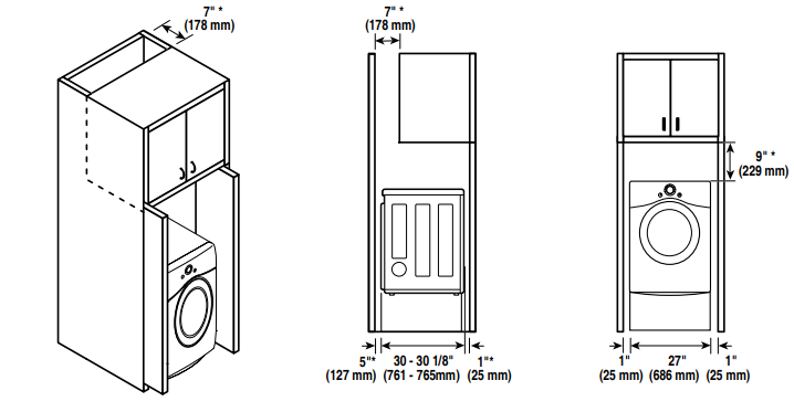
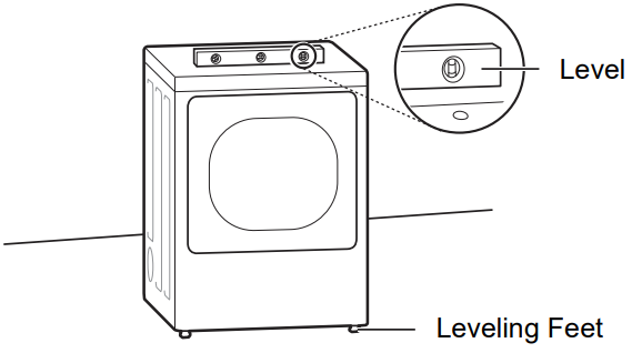
Leveling the Dryer
NOTE
- Adjust the leveling feet only as far as necessary to level the dryer. Extending the leveling feet more than necessary may cause the dryer to vibrate.
- To ensure that the dryer provides optimal drying performance, it must be level. To minimize vibration, noise, and unwanted movement, the floor must be a perfectly level, solid surface.
- Position the dryer in the final location. Place a level across the top of the dryer.
 • All four leveling feet must rest solidly on the floor. Gently push on the top corners of the dryer to make sure that the dryer does not rock from corner to corner.NOTE• If you are installing the dryer on the optional pedestal, you must use the leveling feet on the pedestal to level the dryer. The dryer leveling feet should be fully retracted.
 - Use an adjustable wrench to turn the leveling feet. Unscrew the legs to raise the dryer or screw in the legs to lower it. Adjust the leveling feet until the dryer is level from side to side and front to back. Make sure that all four leveling feet are in firm contact with the floor.
 • All four leveling feet must rest solidly on the floor. Gently push on the top corners of the dryer to make sure that the dryer does not rock from corner to corner.NOTE• If you are installing the dryer on the optional pedestal, you must use the leveling feet on the pedestal to level the dryer. The dryer leveling feet should be fully retracted.
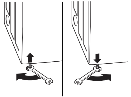
Reversing the Door
Tools Required
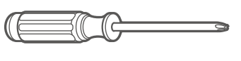
- Phillips screwdriver
- Large flat-blade screwdriver (recommended for hinge screws if they are tight or your Phillips screwdriver is worn)
- Small flat-blade screwdriver (for lifting out parts)
![]() WARNING
WARNING
To reduce the risk of damage to the dryer, property damage, or personal injury, follow basic precautions, including the following:
- Support the door with a stool or box that fits under the door, or have an assistant support the weight of the door.
- Avoid dropping the door.
- Unplug the dryer or turn off the power at the main circuit breaker before beginning door reversal.
- Always reverse the door BEFORE stacking the dryer on top of the washer.
Door Reversal InstructionsThe instructions here are for changing the door swing from a right to a left side hinge. If the door has been reversed, and it is necessary to change it back, use care when following these instructions. Some of the illustrations and the left/right references will be reversed, and you will need to read the instructions carefully.
![]() WARNING
WARNING
- Be sure to support the weight of the door before removing the hinge screws.
-
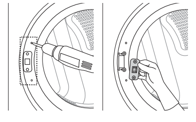
- Open the door and remove the two decorative screws, two latch screws, and the latch on the catch side with a screwdriver. Save these for step 4.
- Open the door and remove the two decorative screws, two latch screws, and the latch on the catch side with a screwdriver. Save these for step 4.
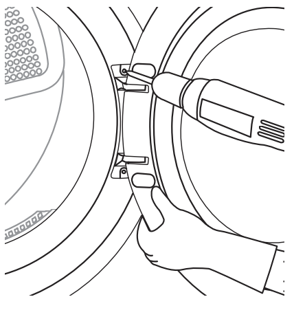
- While supporting the door, remove the 2 screws on the door hinge. Remove the door.
- Turn the door upside down and line up the holes in the hinge with the holes on the opposite side of the cabinet. Reinstall the door with the screws removed in step 2. WARNING• Be sure to support the weight of the door before installing the hinge screws.
- Install the two decorative screws, the latch, and two latch screws removed in step 1 on the opposite side from which they were removed.
- Check that the door closes properly.

Installing the Side Vent Kit
![]() WARNINGTo reduce the risk of serious injury, death or property damage, follow basic precautions, including the following:
WARNINGTo reduce the risk of serious injury, death or property damage, follow basic precautions, including the following:
- Use long-sleeved gloves and safety glasses.
- Use a heavy metal vent.
- Do not use plastic or thin foil ducts.
- Clean old ducts before installing this dryer.
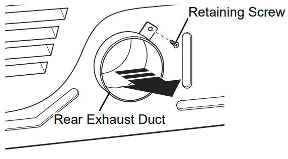
Your new dryer is configured to vent to the rear. It can also vent to the bottom or side (right-side venting is not available on gas models).An adapter kit, part number 383EEL9001B, may be purchased from your LG retailer. This kit contains duct components necessary to change the dryer vent location.
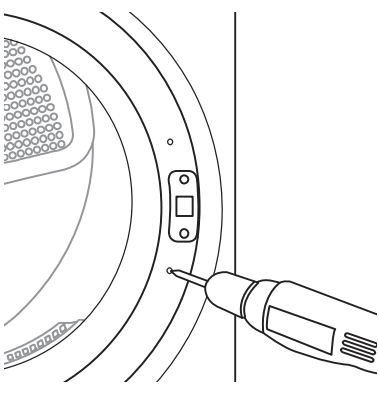
- Remove the rear exhaust duct retaining screw.Pull out the exhaust duct. Option 1: Side Venting
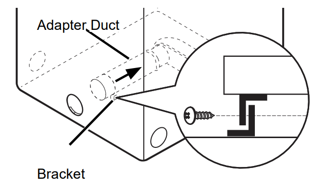
- Press the tabs on the knockout and carefully remove the knockout for the desired vent opening (right-side venting is not available ongas models). Press the adapter duct onto the blower housing and secure it to the base of the dryer as shown.
 Option 1: Side Venting
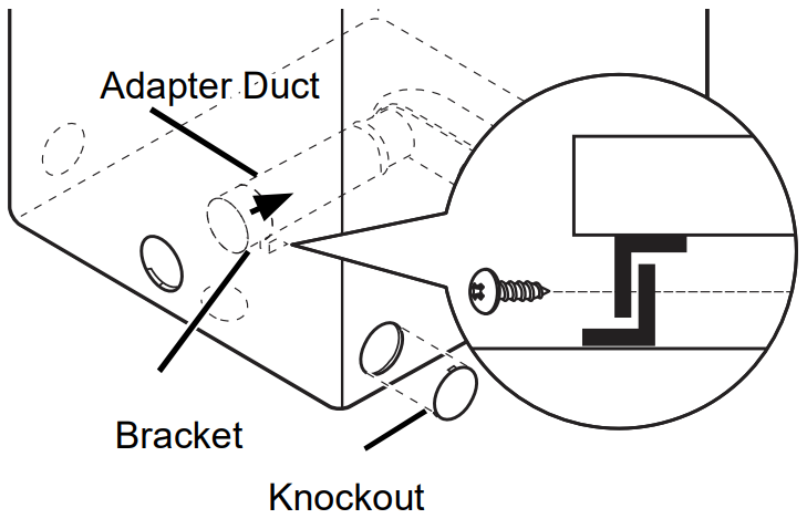
Preassemble a 4-inch (10.2 cm) elbow to the next 4-inch (10.2 cm) duct section, and secure all joints with duct tape. Be sure that the male end of the elbow faces AWAY from the dryer. Insert the elbow/duct assembly through the side opening and press it onto the adapter duct. Secure it in place with duct tape. Be sure that the male end of the duct protrudes 1.5 inches (3.8 cm) to connect the remaining ductwork. Attach the cover plate to the back of the dryer with the included screw.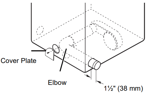
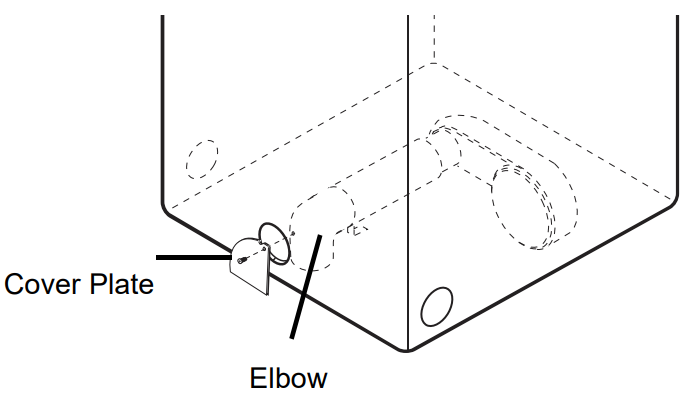
Option 2: Bottom Venting
- Press the adapter duct onto the blower housing and secure it to the base of the dryer as shown.
- Insert the 4-inch (10.2 cm) elbow through the rear opening and press it onto the adapter duct. Be sure that the male end of the elbow faces down through the hole in the bottom of the dryer. Secure it in place with duct tape. Attach the cover plate to the back of the dryer with the included screw.
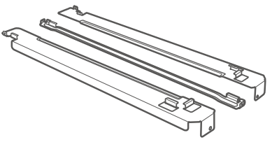
Stacking the DryerStacking Kit InstallationThis stacking kit includes:
- Two (2) side rails
- One (1) front rail
- Four (4) screws
Tools Needed for Installation:
- Phillips screwdriver
WARNINGTo reduce the risk of electrical shock, fire, explosion, property damage, serious injury, or death, follow basic precautions, including the following:
- The weight of the dryer and the height of installation make this stacking procedure too risky for one person. Two or more people arerequired when installing the stacking kit.
- Do not use the stacking kit with a gas dryer in potentially unstable conditions such as a mobile home.
- Place the washer on a solid, stable, level floor capable of supporting the weight of both appliances.
- Do not stack the washer on top of the dryer.
- If appliances are already installed, disconnect them from all power, water, or gas lines and from draining or venting connections.
To ensure safe and secure installation, please observe the following instructions.
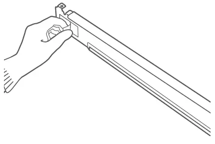
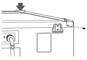
- Make sure the surface of the washer is clean and dry. Remove paper backing from the tape on one of the stacking kit side brackets.
- Fit the side bracket to the side of the washer top as shown in the below illustration. Firmly press the adhesive area of the bracket to the washer surface. Secure the side bracket to the washer with a screw on the backside of the bracket.Repeat steps 1 and 2 to attach the other side bracket.
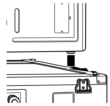
- Place the dryer on top of the washer, fitting the dryer feet into the side brackets as illustrated. Avoid finger injuries; do not allow fingers to be pinched between the washer and dryer.Slowly slide the dryer toward the back of the washer until the side bracket stoppers catch the dryer feet.
Insert the front rail between the bottom of the dryer and the top of the washer. Push the front rail toward the back of the washer until it comes in contact with the side rail stoppers.Install the two retaining screws to secure the front rail to the side rails.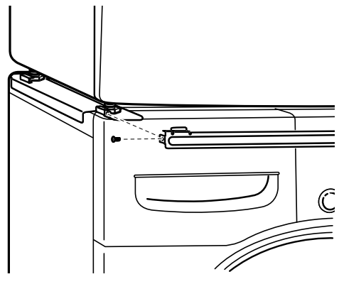 Venting the Dryer
![]() WARNINGTo reduce the risk of fire or explosion, electric shock, property damage, injury to persons or death when using this appliance, follow basic safety precautions, including the following:
WARNINGTo reduce the risk of fire or explosion, electric shock, property damage, injury to persons or death when using this appliance, follow basic safety precautions, including the following:
- Do not crush or collapse ductwork.
- Do not allow ductwork to rest on or contact sharp objects.
- If connecting to existing ductwork, make sure it is suitable and clean before installing the dryer.
- Venting must conform to local building codes.
- Gas dryers MUST exhaust the outdoors.
- Use only 4-inch (10.2 cm) rigid, semi-rigid or flexible metal ductwork inside the dryer cabinet and for venting outside.
- To reduce the risk of fire, combustion, or accumulation of combustible gases, DO NOT exhaust dryer air into an enclosed andunventilated area, such as an attic, wall, ceiling, crawl space, chimney, gas vent, or concealed space of a building.
- To reduce the risk of fire, DO NOT exhaust the dryer with plastic or thin foil ducting.
- The exhaust duct must be 4-inch (10.2 cm) in diameter with no obstructions. The exhaust duct should be kept as short as possible. Make sure to clean any old ducts before installing your new dryer.
- Rigid, semi-rigid or flexible metal ducting is recommended for use between the dryer and the wall. All non-rigid metal transition ducts must be UL-listed. The use of other materials for transition ducts could affect drying time.
- DO NOT use sheet metal screws or other fasteners which extend into the duct that could catch lint and reduce the efficiency of the exhaust system. Secure all joints with duct tape.
- Do not exceed the recommended duct length limitations noted in the chart. Failure to follow these instructions may result in extended drying times, fire or death.
![]() WARNING
WARNING
- Ductwork is not provided with the dryer. You should obtain the necessary ductwork locally. The vent hood should have hinged dampers to prevent backdraft when the dryer is not in use.
- The total length of the flexible metal duct must not exceed 8 ft. (2.4 m).
Ductwork
| Wall Cap Type | Numberof 90°Elbows | Maximumlength of 4-inchdiameter rigidmetal duct |
Recommended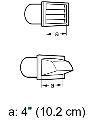 |
0 | 65 ft.(19.8 m) |
| 1 | 55 ft.(16.8 m) | |
| 2 | 47 ft.(14.3 m) | |
| 3 | 36 ft.(11.0 m) | |
| 4 | 28 ft.(8.5 m) | |
Use only for shortrun installations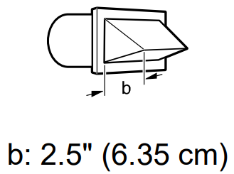 |
0 | 55 ft.(16.8 m) |
| 1 | 47 ft.(14.3 m) | |
| 2 | 41 ft.(12.5 m) | |
| 3 | 30 ft.(9.1 m) | |
| 4 | 22 ft.(6.7 m) |
NOTE
- Deduct 6 ft. (1.8 m) for each additional elbow. Do not use more than four 90° elbows.
- In Canada, only those foil-type flexible ducts, if any, specifically identified for use with the appliance by the manufacturer should be used. In the United States, only those foil-type flexible ducts, if any, specifically identified for use with the appliance by the manufacturer and that comply with the Outline for Clothes Dryer Transition Duct, Subject 2158A should be used.
Routing and Connecting Ductwork
NOTEFollow the guidelines below to maximize drying performance and reduce lint buildup and condensation in the ductwork. Ductwork and fittings are NOT included and must be purchased separately.
- Use 4-inch (10.2 cm) diameter rigid, semi-rigid, or flexible metal ductwork.
- The exhaust duct run should be as short as possible.
- Use as few elbow joints as possible.
- The male end of each section of the exhaust duct must point away from the dryer.
- Use duct tape on all duct joints.
- Insulate ductwork that runs through unheated areas Inc in order to reduce condensation and lint buildup on duct surfaces.
- Incorrect or inadequate exhaust systems are not covered by the dryer warranty. Dryer failures or services required because of such exhaust systems will not be covered by the dryer warranty.
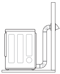
Correct VentingIncorrect Venting
 Incorrect Venting
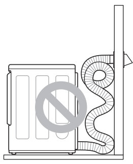
Connecting the Inlet Hose (Steam Models)
The dryer must be connected to the cold water tap using the new water supply hose. Do not reuse old hoses.
NOTE
- Water supply pressure must be between 20 and 120 psi (138—827 kPa).
- Do not strip or cross-thread when connecting the inlet hose to the valve.
- If the water supply pressure is more than 800 kPa, a pressure-reducing valve should be installed.
- Periodically check the condition of the hose and replace the hose if necessary.
- Replace inlet hoses after 5 years of use to reduce the risk of hose failure.
- Record hose installation or replacement dates on the hoses for future reference.
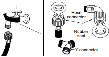
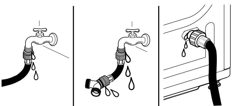
- Check the rubber seal at each end of the inlet hoses.Two ru ber seals are supplied with each inlet hose.They are used for preventing water leaks. Make sure the connection to the cold water tap is tight.
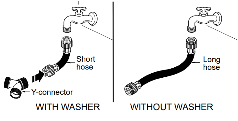
- Check the installation type.Connect all water supply hoses tightly by hand and then tighten another 2/3 turn with pliers.WITH WASHER: When connecting the dryer to the same faucet as a washer.a. Shut off the cold water tap and remove the washer hose.b. Connect the short hose to the Y-connector using one of the rubber seals.c. Connect the other end of the short hose to the cold water faucet.d. Connect the long dryer hose to one side of the Y-connector and connect the washer hose to the other side.WITHOUT WASHER: If the dryer does not share the cold water tap with a washer.a. Connect the straight end of the long hose to the cold water faucet.NOTE• Before connecting the water line to the dryer, flush several gallons of water into a drain or bucket. This will help prevent foreign particles such as sand and scale from clogging the dryer inlet valve.• Do not overtighten. Damage to the coupling may result.
- Connect the hose to the dryer. Connect the water supply hose to the dryer inlet valve tightly by hand and then tighten another 2/3 turn with pliers.Make sure that there are no kinks in the hoses and that they are not crushed.
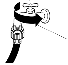
- Turn on the cold water faucet.
- Check for leaks at the Y-connector (if used) and in all hoses.
 Connect all water supply hoses tightly by hand and then tighten another 2/3 turn with pliers.WITH WASHER: When connecting the dryer to the same faucet as a washer.a. Shut off the cold water tap and remove the washer hose.b. Connect the short hose to the Y-connector using one of the rubber seals.c. Connect the other end of the short hose to the cold water faucet.d. Connect the long dryer hose to one side of the Y-connector and connect the washer hose to the other side.WITHOUT WASHER: If the dryer does not share the cold water tap with a washer.a. Connect the straight end of the long hose to the cold water faucet.NOTE• Before connecting the water line to the dryer, flush several gallons of water into a drain or bucket. This will help prevent foreign particles such as sand and scale from clogging the dryer inlet valve.• Do not overtighten. Damage to the coupling may result.
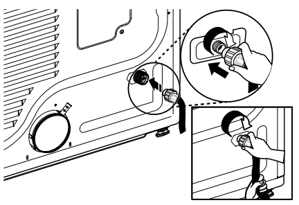
NOTE
- If any leaks are found, shut off the water faucet, remove the hose, and check the condition of the rubber seal.
Connecting Gas Dryers
WARNINGTo reduce the risk of fire or explosion, electric shock, property damage, injury to persons, or death when using this appliance, follow requirements including the following:Electrical Requirements for Gas Models Only
- Do not, under any circumstances, cut or remove the third (ground) prong from the power cord.
- For personal safety, this dryer must be properly grounded.
- This dryer must be plugged into a 120-VAC, 60-Hz. grounded outlet protected by a 15-ampere fuse or circuit breaker.
- Where a standard 2-prong wall outlet is encountered, it is your personal responsibility and obligation to have it replaced with a properly grounded 3-prong wall outlet.
ELECTRIC SHOCK HAZARDFailure to follow safety warnings could result in serious injury
- This dryer is equipped with a three-prong grounding plug for protection against shock hazards and should be plugged directly into aproperly grounded three-prong receptacle. Do not cut or remove the grounding prong from this plug.
Gas Supply Requirements
- As shipped from the factory, this dryer is configured for use with natural gas (NG). It can be converted for use with propane (LP) gas.Gas pressure must not exceed 8-inch (20.4 cm) water column for NG, or 13-inch (33.1 cm) water column for LP.
- A qualified service or gas company technician must connect the dryer to the gas service.
- Isolate the dryer from the gas supply system by closing its individual manual shutoff valve during any pressure testing of the gas supply.
- DO NOT attempt any disassembly of the dryer; disassembly requires the attention and tools of an authorized and qualified service technician or company.
- Securely tighten all gas connections.
- Connect the dryer to the type of gas shown on the nameplate.
![]() WARNINGGas Supply Requirements (continued)
WARNINGGas Supply Requirements (continued)
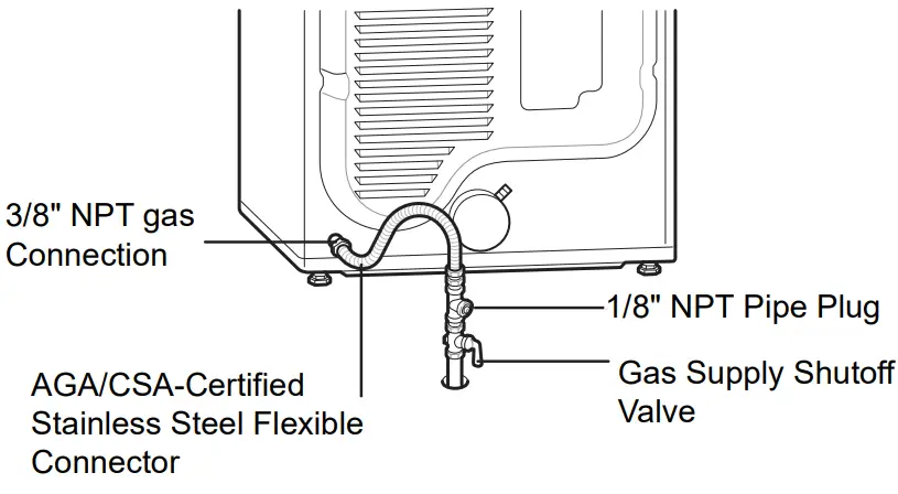
- Supply line requirements: Your laundry room must have a rigid gas supply line to your dryer. In the United States, an individual manual shutoff valve MUST be installed within at least 6 ft. (1.8 m) of the dryer, in accordance with the National Fuel Gas Code ANSI Z223.1 or Canadian gas installation code CSA B149.1. A 1/8-inch NPT pipe plug must be installed.
- If using a rigid pipe, the rigid pipe should be 0.5-inch IPS. If acceptable under local codes and ordinances and when acceptable to your gas supplier, 3/8-inch approved tubing may be used where lengths are less than 20 ft. (6.1 m). Larger tubing should be used for lengths in excess of 20 ft. (6.1 m).
- To prevent contamination of the gas valve, purge the gas supply of air and sediment before connecting the gas supply to the dryer. Before tightening the connection between the gas supply and the dryer, purge the remaining air until the odor of gas is detected.
- DO NOT use an open flame to inspect for gas leaks. Use a noncorrosive leak detection fluid.
- Use only a new AGA- or CSA-certified gas supply line with flexible stainless steel connectors.
- Use Teflon tape or a pipe-joint compound that is insoluble in propane (LP) gas on all pipe threads.
Connecting the Gas Supply
- Installation and service must be performed by a qualified installer, service agency, or gas supplier.
- Use only a new stainless steel flexible connector and a new AGA-certified connector.
- A gas shutoff valve must be installed within 6 ft. (1.8 m) of the dryer.
- The dryer is configured for natural gas when shipped from the factory. Make sure that the dryer is equipped with the correct burner nozzle for the type of gas being used (natural gas or propane gas).
- If necessary, the correct nozzle (for the LP nozzle kit, order part number 383EEL3002D) should be installed by a qualified technician and the change should be noted on the dryer. All connections must be in accordance with local codes and regulations. Gas dryers MUST exhaust the outdoors.
NOTE
- In the Commonwealth of Massachusetts: This product must be installed by a licensed plumber or gas fitter. When using ball-type gas shut-off valves, they shall be T-handle-type. A flexible gas connector, when used, must not exceed 3 feet.
This dryer is configured from the factory for natural gas (NG). If the dryer is to be used with propane (LP) gas, it must be converted by a qualified service technician.
- Make sure that the gas supply to the laundry room is turned OFF and the dryer is unplugged. Confirm that the type of gas available in your laundry room is appropriate for the dryer.
- Remove the shipping cap from the gas fitting at the back of the dryer. Be careful not to damage the threads of the gas connector when removing the shipping cap.
- Connect the dryer to your laundry room’s gas supply using a new flexible stainless steel connector with a 3/8-inch NPT fitting.NOTE• DO NOT use old connectors.
- Securely tighten all connections between thedryer and your laundry room’s gas supply.
- Turn on your laundry room’s gas supply.
- Check all pipe connections (both internal and external) for gas leaks with a noncorrosive leak-detection fluid.
- Proceed to Vent the Dryer.
High-Altitude InstallationsThe BTU rating of this dryer is AGA-certified for elevations below 10,000 feet.If your gas dryer is being installed at an elevation above 10,000 feet, it must be derated by a qualified technician or gas supplier.
Connecting Electric Dryers
 WARNINGTo reduce the risk of fire or explosion, electric shock, property damage, injury to persons, or death when using this appliance, followrequirements including the following:Electrical Requirements forElectric Models Only
- The wiring and grounding must conform to the latest edition of the National Electrical Code, ANSI/NFPA 70 and all applicable localregulations. Please contact a qualified electrician to check your home’s wiring and fuses to ensure that your home has adequate electrical power to operate the dryer.
- This dryer must be connected to a grounded metal, permanent wiring system, or an equipment-grounding conductor must be run with the circuit conductors and connected to the equipment-grounding terminal or lead on the dryer.
- The dryer has its own terminal block that must be connected to a separate 230 VAC, 60-Hertz, single-phase circuit, fused at 30 amperes (the circuit must be fused on both sides of the line).ELECTRICAL SERVICE FOR THE DRYER SHOULD BE OF THE MAXIMUM RATED VOLTAGE LISTED ON THE NAMEPLATE. DO NOT CONNECT THE DRYER TO THE 110-, 115-, OR 120-VOLT CIRCUIT.
- If the branch circuit to the dryer is 15 ft. (4.5 m) or less in length, use UL (Underwriters Laboratories) listed No.-10 AWG wire (copperwire only), or as required by local codes. If over 15 ft. (4.5 m), use UL-listed No.-8 AWG wire (copper wire only), or as required by local codes.Allow sufficient slack in the wiring so the dryer can be moved from its normal location when necessary.
- The power cord (pigtail) connection between the wall receptacle and the dryer terminal block IS NOT supplied with the dryer. Type of pigtail and gauge of wire must conform to local codes and with instructions on the following pages.
WARNING
- A 4-wire connection is required for all mobile and manufactured home installations, as well as all new construction after January 1, 1996. A 4-wire connection must be used where local codes do not permit grounding through the neutral wire.
- Do not modify the plug and internal wire provided with the dryer.
- The dryer should be connected to a 4-hole outlet.
- If the plug does not fit the outlet, a proper outlet will need to be installed by a qualified electrician.
- Connect the power cord to the terminal block.Each colored wire should be connected to the same color screw. The wire color indicated on the manual is connected to the same color screw in the block.
- Grounding through the neutral conductor is prohibited for (1) new branch-circuit installations, (2) mobile homes, (3) recreational vehicles, and (4) areas where local codes prohibit grounding through the neutral conductor.
- This dryer is supplied with the neutral wire grounded. This white ground wire MUST BE MOVED to the neutral terminal when a 4-wire cord is to be used, or where grounding through the neutral conductor is prohibited.
NOTE
- For electrical requirements for mobile or manufactured homes, see Special Electrical Requirements.
Special Electrical Requirements
(For Mobile or Manufactured Homes)
- Any installation in a manufactured or mobile home must comply with the Manufactured Home Construction and Safety Standards Title 24 CFR, Part 3280 or Standard CAN/ CSA 2240 MH and local codes and ordinances If you are uncertain whether your proposed installation will comply with these standards, please contact service and installation professional for assistance.
- A 4-wire connection is required for all mobile and manufactured home installations, as well as all new construction after January 1, 1996.
- A gas dryer must be permanently attached to the floor
- The electrical connection for an electric dryer must be a 4-wire connection. More detailed information concerning the electrical connection is provided in the section Connecting Electric Dryers.
- To reduce the risk of combustion and fire, the dryer must be vented to the outside.
- DO NOT vent the dryer under a manufactured home or mobile home.
- Electric dryers may be vented to the outside using the back, left, right, or bottom panel.
- Gas dryers may be vented to the outside using the back, left, or bottom panel. Gas dryers may not be vented to the outside using the right-side panel because of the burner housing.
- The dryer exhaust duct must be affixed securely to the manufactured or mobile home structure, and the exhaust duct must be made of a material that will resist fire and combustion. It is recommended that you use a rigid, semi-rigid, or flexible metal duct.
- DO NOT connect the dryer exhaust duct to any other duct, vent, chimney, or exhaust duct.
- Make sure the dryer has adequate access to outside fresh air to ensure proper operation. The opening for outside fresh air must be at least 25 sq. in (163 cm2).
- It is important that the clearance of the duct from any combustible construction be at least 2 inches (5 cm), and when venting the dryer to the outdoors, the dryer should be installed with a clearance of at least 1 inch (2.5 cm) at the sides and back of the
- Please be aware that venting materials are not supplied with the dryer. You must obtain the venting materials necessary for proper installation.
Final Installation CheckOnce you have completed the installation of the dryer and it is in its final location, confirm proper operation with the following tests and Installation Test (Duct Check).
Testing Dryer HeatingGAS MODELSClose the dryer door and press the Power button to turn the dryer on. Press the Time Dry and Start/ Pause buttons to start the test. When the dryer starts, the igniter should ignite the main burner.NOTE
- If all air is not purged from the gas line, the gas igniter may turn off before the main burner ignites. If this happens, the igniter will reattempt gas ignition after approximately two minutes.
ELECTRIC MODELSClose the dryer door and press the Power button to turn the dryer on. Press the Time Dry and Start/ Pause buttons to start the test. The exhaust air should be warm after the dryer has been operating for 3 minutes.Checking AirflowEffective dryer operation requires proper airflow.The adequacy of the airflow can be measured by evaluating the static pressure. Static pressure in the exhaust duct can be measured with a manometer, placed on the exhaust duct approximately 2 ft. (60.9 cm) from the dryer. Static pressure in the exhaust duct should not exceed 0.6 inches (1.5 cm).The dryer should be checked while the dryer is running with no load.
Checking LevelnessOnce the dryer is in its final location, recheck the dryer to be sure it is level. Make sure it is level front to back and side to side, and that all four leveling feet are in firm contact with the floor.
Installation Test (Duct Check)
Once you have completed the installation of the dryer, use this test to make sure the condition of the exhaust system is adequate for the proper operation of the dryer. This test should be performed to alert you to any serious problems in the exhaust system of your home.Your dryer features Flow Sense™, an innovative sensing system that automatically detects blockages and restrictions in dryer ductwork.Keeping ductwork clean of lint buildup and free of restrictions allows clothes to dry faster and reduces energy use.
NOTE
- The dryer should be cool before starting this test. If the dryer was warmed up during installation, run the Air Dry cycle for a few minutes to reduce the interior temperature.
 report this ad
Activating the Installation Test
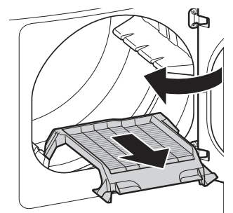
- Remove the drying rack and literature, and then close the door.Do not load anything in the drum for this test, as it may affect the accuracy of the results.
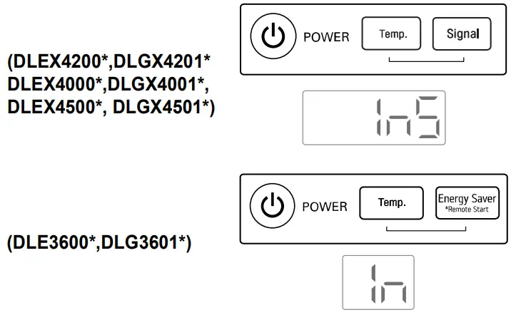
- (DLEX4200*, DLGX4201*, DLEX4000*, DLGX4001*, DLEX4500*, DLGX4501*) Press and hold Signal and Temp.(DLE3600*, DLG3601*) Press and hold Energy Saver and Temp.Then press the Power button.(On models with a glass touch control panel, press the Power button then IMMEDIATELY press and hold the other 2 buttons.This button sequence activates the installation test. The code will display if the activation is successful.
- Press the START/PAUSE button.The dryer will start the test, which will last a few minutes. The heat will be turned on and the temperatures in the drum will be measured.
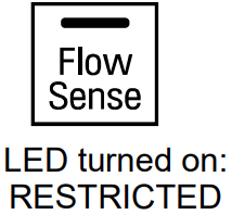
- Check the display for results.(DLEX4200*,DLGX4201*, DLEX4000*, DLGX4001*, DLEX4500*, DLGX4501*)During the test cycle, monitor the Flow Sense™display on the control panel. If the Flow Sense™LED has not turned on, when the cycle ends, the exhaust system is adequate. If the exhaust system is severely restricted, the Flow Sense™ LED will turn on. Other problems may also be shown with error codes. See the chart on the next page for error code details and solutions.The Flow Sense™ LED indicates that the exhaust system is severely restricted. Have the system checked immediately, as performance will be poor.(DLE3600*,DLG3601*)During the test cycle, monitor the Flow Sense™ display on the control panel. If no bars are displayed, when the cycle ends, the exhaust system is adequate. If the exhaust system is severely restricted, the display will show four bars. Other problems may also be shown with error codes. Refer to the next page for error code details and solutions.Four bars indicate that the exhaust system is severely restricted. Have the system checked immediately, as performance will be poor.
- End of cycle.(DLEX4200*,DLGX4201*, DLEX4000*, DLGX4001*, DLEX4500*, DLGX4501*)At the end of the test cycle, will display.The test cycle will end and the dryer will shut off automatically after a short delay.(DLE3600*,DLG3601*)At the end of the test cycle, will display. The test cycle will end and the dryer will shut off automatically after a short delay.
 The Flow Sense™ LED indicates that the exhaust system is severely restricted. Have the system checked immediately, as performance will be poor.(DLE3600*,DLG3601*)During the test cycle, monitor the Flow Sense™ display on the control panel. If no bars are displayed, when the cycle ends, the exhaust system is adequate. If the exhaust system is severely restricted, the display will show four bars. Other problems may also be shown with error codes. Refer to the next page for error code details and solutions.
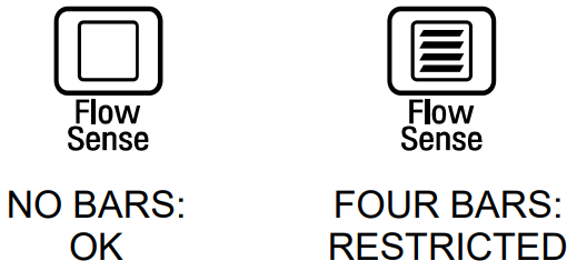 Four bars indicate that the exhaust system is severely restricted. Have the system checked immediately, as performance will be poor.
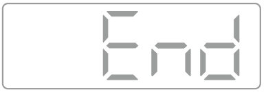 (DLE3600*,DLG3601*)At the end of the test cycle,
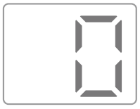
[xyz-ips snippet=”download-snippet”]