LG LCD Network Monitor User Manual
Chapter 1 Safety Precautions
Electricity is used to perform many useful functions, but it can also cause personal injuries and property damage if improperly handled. This product has been engineered and manufactured with the highest priority on safety. However, improper use can result in electric shock and/or fire. In order to prevent potential danger, please observe the following instructions when installing, operating and cleaning the product. To ensure your safety and prolong the service life of your LCD product, please read the following precautions carefully before using the product.
- Read instructions — All operating instructions must be read and understood before the product is operated.
- Keep this manual in a safe place — These safety and operating instructions must be kept in a safe place for future reference.
- Observe warnings — All warnings on the product and in the instructions must be observed closely.
- Follow instructions — All operating instructions must be followed.
- Attachments–Do not use attachments not recommended by the manufacturer. Use of inadequate attachments can result in accidents
- Power connection — The monitor is equipped with a three-pronged grounded plug, a plug with a third (grounding) pin. This plug will fit only into a grounded power outlet as a safety feature. If your outlet does not accommodate the three-wire plug, have an electrician install the correct outlet, or use an adapter to ground the appliance safely. Do not defeat the safety purpose of the grounded plug.
- Power cord protection–The power cords must be routed properly to prevent people from stepping on them or objects from resting on them. Check the cords at the plugs and product.
- Servicing — Do not attempt to service the product yourself. Removing covers can expose you to high voltage and other dangerous conditions. Request a qualified service person to perform servicing.
- Replacement parts — In case the product needs replacement parts, make sure that the service person uses replacement parts specified by the manufacturer, or those with the same characteristics and performance as the original parts. Use of unauthorized parts can result in fire, electric shock and/or other danger.
- Wall mounting — When mounting the product on a wall, be sure to install the product according to the method recommended by the manufacturer.
- Cleaning — Unplug the power cord from the AC outlet before cleaning the product. Use a dry cloth to clean the product. Do not use liquid cleaners or aerosol cleaners.
- Please unplug AC power cord when the device is not used for long time.
- Do not place the monitor on an unstable cart, stand, tripod, bracket, or table.
- Ventilation –The vents and other openings in the cabinet are designed for ventilation. Do not cover or block these vents and openings since insufficient ventilation can cause overheating and/or shorten the life of the product. Do not place the product on a sofa, rug or other similar surface, since they can block ventilation openings. Do not place the product in an enclosed place such as a bookcase or rack, unless proper ventilation is provided or the manufacturer’s instructions are followed.
- When relocating the product placed on a cart, it must be moved with utmost care. Sudden stops, excessive force and uneven floor surface can cause the product drop from the cart.
- Heat sources — Keep the product away from heat sources such as radiators, heaters, stoves and other heat-generating products (including amplifiers).
- Switch on-off time interval should not be less than 3 seconds.
Chapter 2 Packing Content
Upon receipt, please verify that the package contents include the following.
- LCD Monitor
- User Manual
- QC Pass Card
- AC Power supply
- IR remote controllerKind note: when you find the package contents is not corresponding to packing list, please supplier in time. contact the
Chapter 3 Port Interface and Control Modular Instruction
Port:
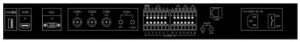
- USB/ (Play): USB port, which can play multimedia files in U disk, and also can do firmware upgrade to LCD network monitor.
- HDMI: HD digital multimedia port, can be compatible with DVI signal VGA.
- It can connect to the computer and other image signal output terminals.
- AV1, AV2: input port for composite video signals.
- AV-OUT: Output port for composite video signals.
- Audio in: PC signals and cvbs corresponding audio input port.
- RS485: Keyboard port for monitor.
- ALARM IN: Alarm input port
- NO NC: Alarm output ports, total 4 pairs
- Audio in out: Audio input and output for video management
- LAN: Network port for video management
- Power: AC power port and switch
Control Modular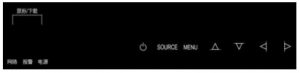
- POWER: Power switch
- SOURCE: Selection of input signal source (for main screen)
- MENU: On& Off OSD menu or in OSD menu, escape current OSD menu control
 In OSD menu, up arrow selection to control
- In OSD menu, down arrow selection to control
- In OSD menu, left arrow selection to control
- In OSD menu, right arrow selection to control or go sub menu page, which equivalent to ENTER button
- Indication LED Monitors running indication light, including network status, running status and alarm status
- USB port: Connect to USB mouse or USB storage device for download and record.
Chapter 4 Remote Controller Instruction
Buttons on remote controller:
| POWER | Power On/Off button |
| MUTE | Mute button |
| ENTER | Enter button |
| EXIT | Exit button |
| SOURCE | Input signal source selection button |
| upward selection | |
| downward selection | |
| rightward selection | |
| leftward selection | |
| MENU | Menu button |
| VGA | VGA(PC) shortcut selection |
| YPbPr | YPbPr signal shortcut selection |
| HDMI | HDMI signal shortcut selection |
| AV | AV signal shortcut selection |
| USB | multimedia USB play |
| DVI | shortcut selection for video management screen
Special Note: pressing |
Chapter 5 OSD Adjustment
Main menu You can adjust all settings of LCD network monitor via OSD menu.
- Press MENU button and show main menu as follows
- Video
- Sound
- Time
- Set
2. Adjust corresponding items according to the instruction
| Item | Function | Range | Remark |
| VIDEO | |||
| Contrast | Adjust difference between light and shade | 0 ~ 100 | |
| Brightness | Adjust balance between light and shade | 0~ 100
|
|
| Color temperature adjustment | To select from “standard”, “warm color”, “cold color”, “SRG” 4 preset modes and “individual set”. When choosing individual setting mode, you can set and adjust red, green and blue respectively. | Only effective for computer mode | |
| Image mode | To select from “standard”, “movement”, “soft” 3 preset modes and “individual set”. When select individual set mode, you can adjust to difference image sets | Only effective for computer and DVI mode | |
| Scaling mode | Select image display ratio (W:H) | Standard 14:9 Full screen Scaling 1 Scaling 2 | |
| Noise Reduction | With 3D processing mode, adjust different level to reduce signal images’ noise interference, to improve image’s sharpness | High/ Medium/ Low/ Off | |
| SOUND | |||
| Equalizer | Adjust the sound equalization in different frequency bands | 120Hz/ 500Hz 1500Hz 5000Hz 10000Hz | |
| Sound mode | Selection from Standard, Movie, Music 3 preset mode and Individual mode. When choosing individual mode, you can make adjustment for different sound frequency | ||
| Surround | Stereo sound output | On/off | |
| Balance | Adjust sound balance | -50 ~ +50 | |
| Auto sound contro | Auto control VOL during switch | On/off | |
| TIME | |||
| Shut down time | shut down time can be set freely | Every day/ Once / Mon~Sat/ Mon~ Fri/ Sun | It can set to Hour and Minute |
| Start up time | Start up time can be set freely | Every day/ Once / Mon~Sat/ Mon~ Fri/ Sun | It can set to Hour and Minute |
| Sleep timing | Sleep time can be set | 10min, 20min, 30min, 60min, 90min | |
| Auto sleep | When auto sleep mode is on, it will automatically enter sleep status according to the sleep time set | ON/ OFF | |
| SET | |||
| Menu language | OSD menu language set | Chinese/English | |
| Backlight mode | It can adjust backlight brightness as per different mode | Backlight mode 1~3 optional | |
| Display time | Adjust the time on screen | 5.10.15 | |
| Menu transparency | Set the transparency of menu background | Low/medium/ high | |
| Factory default | Restore all settings to the original status of factory | ||
| Frame color | Set frame color to sub screens | screens Blue/black | |
| Sound channel | set the current sound from main screen or sub screen | Main screen/ sub screen | |
| Screen switch | t will switch between main screen and sub screen | ||
Chapter 6 Software Operation
Start up &shutdown Start up
- Step plug in power supply;
- Step Device tart up, power indicates on, and device show starting up image.
LoginThe user needs to login when system start up, otherwise, it can not do other operation just except doing image switch, change image’s preview mode, begin/close looping. There are 2 default users in system; User name: admin Password: 123456, User name: user Password: 123456 The rights for the 2 users are different.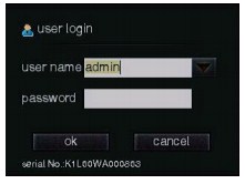 Logout
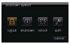
When switching the login users, please click “shutdown system” — “logout”, then it will popup user login interface. ShutdownSoft shutdown
- Step Click “shutdown system” icon in menu, and choose shutdown, then the screen will popup a window of confirming shutdown;
- Step choose “OK”, the device will automatically power off
- Step plug out power supply. Kind note: when the device is in normal shutdown, the system will prompt “the system is shutting down “, at this time, please do not plug out the power, otherwise, it will cause the monitor not working normal.Hardware shutdown Plug out the power cable directly when device is running.
 Hardware shutdown Plug out the power cable directly when device is running.
Reboot
Menu reboot: Step 1: click shutdown system icon, and choose reboot, the screen will popup the window of confirming shutdown; Step 2: Click “OK”, the device will automatically reboot. Kind note: when the device normal reboots, the system will prompt “the system is rebooting…. “, then please do not plug out the power cable at this time, otherwise, it will cause the monitor abnormal working.
Configuration wizard
When the network monitor is first used or upgraded, the user log in, it will popup the configuration wizard. Then you can set general parameters and network parameters. Step 1: General parameter setting. Set the device name, number, date format, system date/time and whether open wizard for next boot, Step 2: Network parameter setting. It can configure IP or PPPOE parameters.
Decode configuration
Decode configuration instructionDecoder usually has two modes: Active and Passive decode modes. Active decoding has four methods of direct-connected device, stream media server, auto redundancy(device priority) and auto redundancy (stream media priority)
- Direct-connected device: it means the decoder actively apply for the media date from IPC, NVR and DVR, and do corresponding decode and display for the data.
- Stream server: it means decoder get the media data of IPC, NVR, DVR from stream media server. This method can reduce the capacity pressure of front-end devices.
- Auto redundancy(device priority): It means streaming from device in priority, when device streaming failed, it will stream from stream server.
- Auto redundancy(stream server priority): It means streaming from stream media in priority, when stream media streaming failed, it will stream from device. Passive decoding mode is that after decoder is connected to the platform through RTSP protocol, platform will inform decoder according to it’s own looping display schedule and display mode, and transmit the media data to the decoder end, then decoder will receive the data and decode them.
Active decoding
Go to decode configuration interface (menu-display-decode config), and the default is active decode mode.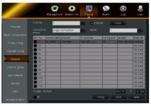 Before networking, each channels status shows not configured, and the preview is all black. After networking, if the devices are smoothly connected, the preview will show images, and channel status shows enabled; If the channel already add the device, but the preview has no image, just showing NO NETWORK VIDEO, then the channel status still shows enabled.
Add device by manual In decode configuration interface, select a decoding channel, click config, or through preview interface, choose “digital channel” on upper left free-floating toolbar, to enter “Add Device”, like the right figure. Click “search”, it will come out all online IPC/ DVR/ NVR/ Decoder information, which includes type, model, IP address, etc. If there are too many online device, you can turn over with clicking icons ![]() Decode channel support adding IPC, NVR, DVR and other device. You also can select decoding channel, channel connection serial number and enable/disable the channel device in this interface.
Decode channel support adding IPC, NVR, DVR and other device. You also can select decoding channel, channel connection serial number and enable/disable the channel device in this interface.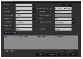
Double click the device in list, the device will be added to the channel, and click “save” to finish adding device operation. You can click “Test” to check whether the added device is successfully connected. Failure test will be of following reasons:
- Device’s username, password, or config port is wrong;
- Network connection timeout: the added device’s internet is disconnected (restart or power off)
- Network connection timeout: the network monitor decoder disconnected. Clear Channel In “channel”. click the chosen channel, and click “clear”, then it will clear the device, you can manually re-add device or do self-networking.
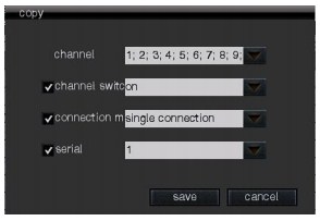
Connection mode Decode config’s active decoding mode support connection mode choice, including single connection and multiple connection. When choosing single connection mode, the serial number is 1. Single connection mode provides the choice of connection serial number. The preview screen will display the image of the device added under the selected serial number. Multiple connection mode provides looping time set. Through related looping configuration, channel can loop all connected device. Copy configuration In Add Device page, click the “Copy” to copy the current configuration to each of the other channels. The user can select the copied parameters according to the actual needs, as figure below:In decode config page, click “copy”, it can copy channel switch, connection mode to each other channels, as figure below.
Self-networkingIs the device is first-time used, it is suggested to use self-networking function. Enter self-networking interface(menu-display management-self-networking), the device will automatically search the online IPC/DVR/NVR/Decoder, and sort the device according to the device name. The page will show device’s protocol type, device name, IP address and other information, as figure below.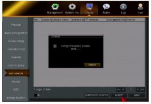 In self-network, choose the searched device and click “save”, this device will be automatically distributed to the specific channel serial number. The rule of distributing channel is default from channel 1 to channel 96. And the rule of distributing serial is that the device will be added to the serial 1, when serial 1 already has other device, then it will be added to serial 2, and so on. It support single /all choose, page turning function. Single channel is configured up to first 32 items. The monitor can max allow 12288 (96x32x4)CH 1080P IPC access. Note: only a few monitor items can support 96 channels. Please prevail in kind. According to the real requirement, the use also can select the specific device, and click “Distribute channel”, then the chosen device will automatically distributed in sort to the channel 1, channel 2, channel 3, and so on.
 The user also can click drop-down list at the channel, to distribute channel for the specific device. Choose the related channel– click Save, then it finished channel distribution, as figure below.
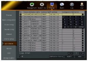 Preview
Preview introduction
After decode configuration self-networking or manual added device gets connection, the preview image will be displayed. In preview interface, move the mouse to the channel upper left, free-floating toolbar will come out. The user can directly do the operation of digital zoom, PTZ control, on/off audio, add/modify device, instant replay or replay by channel, etc .Move the mouse to the button of the monitor, it will show the menu bar. The user can do the operation of main menu, image selection, begin/end looping, alarm management, replay, shut down the monitor, etc.
Icons instruction:
| Icon | Function |
 |
Digital zoom |
 |
PTZ control |
 |
Turn on/off current sound |
 |
Go to digital channel and add device |
 |
Instant replay |
 |
Channel quick replay |
 |
go to one point to view |
 |
Start the channel splicing to video wall |
 |
menu bar display |
 |
go to main menu |
 |
Previous / Next |

|
Begin/end looping |
 |
Start associated channel splicing to video wall |
 |
Group preview |
 |
Channel roaming |
 |
Alarm management, including trigger and clear |
 |
Device playback |
 |
Shutdown system, including logout, shut down and reboot |
 |
Check alarm information |

Preview configuration
Enter “Preview Configuration” interface (main menu– display management– preview configuration), the user can do the operation of alarm screen switch delay, turning on/off audio preview, choosing preview display mode, choosing screen split mode, etc. Alarm screen switch delay can be set 1~10 seconds. When the alarm triggered “pop-up screen”, the preview interface will pop up the associated channel screen. Preview display mode can select stretching mode, smart mode and isometric mode. It is default smart mode, this feature is mainly used to solve IPC display problems in corridor.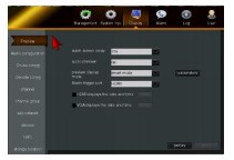 Select the screen split mode, and choose the channel needs to be split, for channel order editing. Select the sub-window, click “X” , the corresponding channel will not display the video. The user can also turn on / off the sub-window audio. For preview patrol, the user can choose fixed screen patrol or multi-screen patrol. If multi-screen patrol, additional tour plan will be needed. It can configure different split mode in different time based on the requirements. Click “start touring(patrol)” in menu, each channels will preview in turn according to the setting of patrol time/choice.
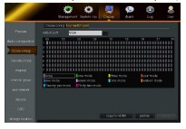 Instruction for patrol:
- It supports the decode and patrol under following preview modes: single screen, three split, four split, five split, seven split, seven split, nine split, sixteen split, twenty-five split, thirty-six split, forty-nine split and sixty-four split; Note: some mode are only suitable for part of items. Please prevail in kind.
- Support 16 channels configuration. Each channel supports different parameter config, including connection mode (single/multiple connection), patrol time config, and channel enable/disable;
- When decoding and patrolling, it supports alarm linkage, that is, when alarm occurs during decoding and patrolling, it can immediately connect and pop up the alarm linkage of the remote device, and record the log;
- When each channel configures remote connection, it supports search, add and connection;
- When beyond the performance, it will prompt “beyond the system’s performance”;
- It does not support configuration of platform connection during patrolling;
- When multiple remote connections are configured in the same channel, the same connection can be configured; When the configured connection is continuous and identical, do not disconnect the connection;
- During patrolling, when configuration is modified (cancel/add remote connection), please restart patrol;
- In different preview mode, it support different audio channel.
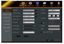
General Parameter
Go to “General Parameter” (Main menu–system management–general parameter), for parameters setting.
- Resolution
- Device name, device number
- Transparency, mouse speed
- Menu standby time
- Date format, system time
- NTP timing, including time zone choice, timing interval, server address In addition to the above parameters, you can also open the configuration wizard on this page. For the configuration wizard, refer to section 3.2 for details. No more details will be given here.
Large screen splicing
Large screen splicing can make free combination of multiple decoders, so that single channel video can be displayed a complete video screen on multiple display terminals. It can be set and operated with the mouse on the local display menu of the decoder, and can be controlled remotely by the decoder WEB interface and platform management software. Large screen splicing configuration Go to “Large screen spicing” (Main menu–System Management–Screen splicing), to set the parameters below. Output resolution: to set the resolution of spliced screed. Multiple resolution are for choice, max support 1920×1080. Splicing mode: multiple splicing mode for choice, max support 4×4 mode. Splicing name: to set the name of video wall. Decoding strategy: it can set smooth or in real time. Associated channel:Button of starting video wall combination in preview menu. This is default to be on. After the parameters is finished setting, click “search” and add the monitor to create video wall. After the large screen splicing is completed, you can double-click the added stitching screen and do modification, as figure right.
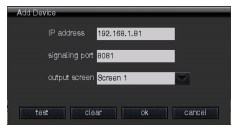 Preview splicing After the video wall is combined, in preview page, click “screen splicing”, and enable associated channel’s screen splicing, or click “start stitching” in channel floating toolbar ICONS, startup screen splicing at any channels.
Network configuration
IP address and DNS address
Go to “Network Configuration” (Main menu–System management–Network config), set network card type, configure device IP address and DNS address. According to the actual working environment, users can manually configure static IP address and DNS address, and also can obtain the dynamic IP address and DNS address through automatic acquisition. The obtained IP address can be checked in the network status (Path: Main Menu-> System Information-> Network Status).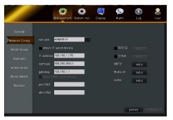
Smart Mouse
Smart mouse, that is, network virtual mouse network, is a technology of other monitors in the network can be controlled by the mouse in one monitor. It can reduce mouse switching operation and improve efficiency, so as to facilitate the management of multiple monitoring devices.
Work Station Set
Enter “intelligent control” (path: the main menu – > system – > intelligent control) interface, click enable, choose the work mode of “workstation”, set up the master server address, master server port, the standby server address and standby server port. When the device is configured as a workstation, the corresponding master server will automatically enable the intelligent control and operate the mouse on the configured master server, so it can achieve the control of the current device.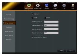 Note: 1. When the main server is normally used, the standby server is equivalent to the workstation. 2. The mouse on the standby server can control the other workstation only when the main server isnot online or crashed.
Server Set
Enter “intelligent control” (path: the main menu – > system – > intelligent control) interface, click enable, choose the work mode “server”, set the port, heartbeat interval, choice of master/standby server, the server address and port, as well as display mode.The server is another working mode relative to the workstation. When the device is configured as a server, you can choose whether to specify the standby server; When configured as a standby server, you must specify the primary server. When abnormal condition happens on master server, such as intelligent control disabled, network off or power off, that is, master server can not intelligent control the work station, then the standby server will be rapid response, switch to a server and control the workstation by virtual mouse. realize the virtual mouse control of the workstation. When uniform patrol is enabled, if the current device’s preview patrol is on or off, then other connected work station’s preview patrol will be on or off uniformly. It is recommended that the user connects the display device to display port with serial no. 1 and then the following configuration. When the user first uses the device, the device will automatically network into a smart control network. The display interface with serial no. 1 is the default server. If the workstation IP address is modified, the user can click “one-click networking” on the server to network device into a smart control network.If the workstation and server is not in the same network segment, the mouse cannot control workstations, so it is suggested that the user go to network configuration, select related network card, to configure workstation IP address.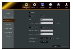
Display Mode Set
When the monitor decoder is configured as server, click “config” next to “common display mode” to enter the display mode configuration interface. It can configure screen display mode, search device, show device list, set workstation and add device, etc.Common display mode For display mode, there are two-screen, three-screen, four screen, nine screen, ect. Beside these, the users can also choose custom mode. Custom mode max support 30 screens.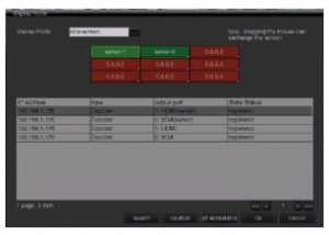 Search Click “search”, the device will automatically search the online DVR/NVR/Decoder, and show the device information in priority which is in the same segment with NVR, including IP address, product type, status and so on. If there are too many online device, you can check with clicking
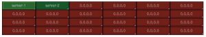
 ![]() First searched device status is “not registered”, click and choose the display box which is not configured, that is, the red area in above figure, and then double-click the device in list, it will add the search device to the
First searched device status is “not registered”, click and choose the display box which is not configured, that is, the red area in above figure, and then double-click the device in list, it will add the search device to the
display box; Or double-click the unconfigured display box to fill in the IP address by manual.
Set as Workstation In list of devices that are searched out, select an unregistered device and click “set workstation”, input the correct username and password, and click “OK”, and click “apply” in smart control interface. Then enter the config interface in common display mode again, the device status has been changed from “unregistered” to “registered”, and the red display box will become green. Only the searched device is registered (that is, set as workstation) and fills in the display box, then the workstation device can be controlled by the mouse on the server device.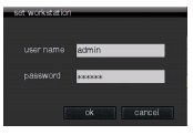
Location In the device list, click the registered device and click “location” to locate the registered device on the server. The located device by server will have an interface prompt.
Device List Management
When the device is registered, it will be added to the list; when the device is offline, it will be removed from the list; When the device does not receive heartbeat for a period of time, it will be removed from the list.The display mode has two screens in row, three screens in row, four screens in row, four screens, nine screens, sixteen screens and twenty-four screens for option.
- Under two screens in row mode, it support to choose 2 device;
- Under three screens in row mode, it support to choose 3 device;
- Under four screens in row mode, it support to choose 4 device;
- Under four-screen mode, it support 2×2 device;
- Under nine-screen mode, it support 3×3 device; Under sixteen-screen mode, it support 4×4 device; Under twenty four-screen mode, it support 4×6 device.
Cursor style
The device support cursor type choice. In Smart Control Server interface, click cursor and choose cursor style. The style includes 32×32 white, 64×64 white/red/yellow/blue/green and 128×128 white /red /yellow/ blue/green.The workstation records the moving status of the net mouse. When net mouse moves in, the cursor will be displayed. And when net mouse moves out, it will be hidden. while the net mouse moves out, the local mouse on the workstation will be displayed normally, but when the local mouse does not operated for a period of time, the cursor will be hidden.When the device is configured as a server, click “Set” next to the “cursor” to configure the cursor style. There are 11 different sizes and colors for selection. After the cursor style on server is modified, the workstation’s cursor style will be displayed synchronously.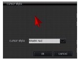
Chapter 7 Troubleshooting
- Why IP monitor can not control PTZ camera? A: It will have two conditions.
- When IP monitor control NVR or IP PTZ, it requires to input correct username and password, otherwise itcan not control.
- It does not support to control the IP PTZ which connects to NVR/DVR.
- When IP monitor previews IPC, why screen is visible for multiple images, but black for single image?
- first, IPC has multiple code streams, each of which can be independently configured. Secondly, the IPmonitor connects to IPC, the sub-stream is used by default for multiple images. And main stream is used by default for single image. So please check whether IPC support High Profile and Main Profile coding. When IPC’s main stream has the code that IP monitor does not support, it will cause the single screen showing black.
[xyz-ips snippet=”download-snippet”]