LG U IoT Switch User Manual
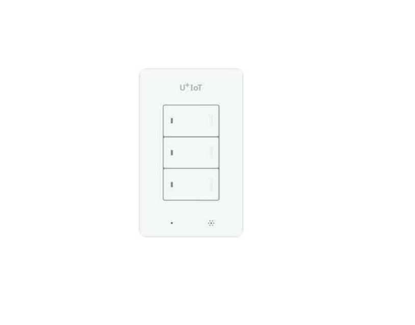
U + IOT Switch
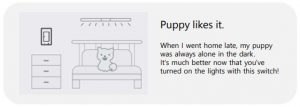
Even if you leave the lights on or leave the house empty for a long time, you’ll feel safe. You can see where your home’s Lights are on or off anytime, anywhere.
Turn on and off on your smartphone Scheduling
 Voice Control
 Concurrent Control
 Automatic Operation

Key Features
Turn off and turn on with your smartphoneAnytime, anywhere, with the smart phone app You can turn off and turn on the lights in the house.SchedulingYou can turn off and turn on the lights automatically at any time. You can use it like an alarm if you set it in time for the weather.Voice ControlThe switch can be controlled by voice using AI Speaker.Auto OperationIf one of the reserved devices runs, The lights in the house are off and on.Temperature/humidity measurementYou can check the temperature and humidity of the location where the switch is installed in real time through the smartphone app.Switch over-temperature shutIf the switch overheats, the switch will automatically turn off for safety. This can occur if the product is over-qualified or if the temperature exceeds the recommended installable temperature. After checking the environment, turn off the switch for a while and then use it again.If this occurs continuously, please contact the customer center at 101 without any country number.
Product Components
Before installation, please check the components. Please keep the warranty statement in the manual for A/S.
IoT Switch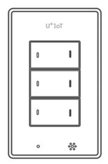 User’s Manual
 Installation Guide
 Fastening screw
Product Name
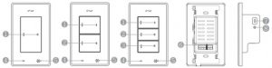
- Turn off and turn on the light connected to button 1
- Turn off and turn on the light connected to button 2
- Turn off and turn on the light connected to button 3
- Reset Button: Reset Device
- Temperature/humidity sensor: Measurement of temperature and humidity values at the place where the switch is installed
- Wire connection terminal: terminal connecting the electric light wires
- Terminal 1 (Gradle 1) : Connection of the electric light wires to switch 1.
- Terminal 2 (2) : Connection of the electric light wires to switch 2.
- Terminal 3 (3 phrases): Connecting electrical wires to switch 3.
- Common (COM) : Common Line Connection
 This product is dedicated to the Gyeongdong line and has a mask length of 12mm.
- Charging port : 5-pin USB only charging port
- Charge indication LED: Green light when charging is complete (required for charging before installation)
 This product is dedicated to the Gyeongdong line and has a mask length of 12mm.
Device Specifications
|
Category |
Specification |
| Size | 122.5 × 75.0 × 43(mm) |
| Power | 220V~,60Hz, 600W(SSD-105)/1200W(SSD-205)/1800W(SSD-305) |
| Recommended installable temperature | -10℃ ~ 45℃ |
Recommended electric capacity: Based on electric power consumption
- One of the switches must be connected to a lamp with a light capacity of 8W or higher.
|
Sortation |
Light No. 1 |
No. 2 light |
No. 3 light |
maximum capacity |
| 1 button switch | 8~600W | 600W | ||
| 2 button switch | 8~600W | ~600W | 1200W | |
| 3 button switch | 8~600W | ~600W | ~600W | 1800W |
- The above light capacity may vary depending on the installation environment and the condition of the lamp.
- The combined power consumption of the connected lamp must not be greater than the maximum amount.
- This device may be radio-borne while in use, and may receive harmful confusions from other devices.
Using the IoT Switch


How to use
- Once the IoT switch is installed and the app is connected, the following functions are available
Turn off and turn on the light (press button to the right)When the light is off, the LED light on the left side of the button turns on. The LED lamp turns off when the light is on.
Connecting and Disconnecting DevicesPress and hold the bottom button of the switch button for at least 5 seconds.
- If the red LED lamp on the left side of the button flashes 6 times, release your hand.
- After approximately 30 seconds, the connection or release is complete.
Initializing the product (Product
- Press the bottom button of the IoT switch for more than 10 seconds. After 5 seconds, keep pressing the button even if the red LED lamp blinks.
- After 10 seconds, the flashing of the red LED lamp pauses for a while, then when it flashes again, it releases its hands.
- When the instrument is initialized, all lights connected to the IoT switch are switched off and all green LED lamps on the left side of the button are turned on.
Using the app
You can view the list of registered switches and their status at a glance on the Home screen.
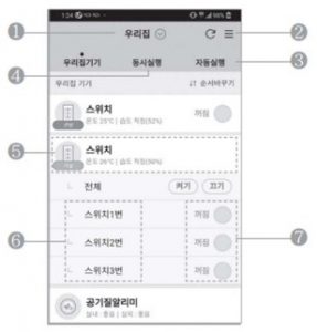
- Location: You can register and change places using the IoT switch.
- Menu: You can manage your ID and device.
- Automatic execution: When one IoT device is executed, other IoT devices can be automatically turned off or turned on.
- Simultaneous execution: Multiple IoT devices can be turned on and off at a time.
- Temperature/humidity information: You can check the temperature/humidity information at the place where the IoT switch is installed.
- Details page : You can schedule the time to turn on or off by switch button, and check the history of use, etc.
- Operation button: You can turn off and turn on the light power connected to the switch.
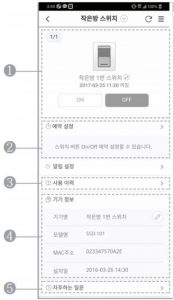
Using the app
On the Switch Details page, you can set the schedule to run by button and check the usage, and so on
- Check/control the status of the unit: The status of the current switch can be checked and the associated lights can be turned on or off.
- Schedule Settings : Switch on/off can be set by time/day.
- History of use: You can view the history of switch usage over the last 1 month.
- Device information: Shows the device name, model name, and installation date.
- Frequently Asked Questions: You can solve your questions by checking the questions and answers you frequently ask.
Safety Rules
- If you do not comply with the following, you may be at risk of serious injury or death. Be sure to read it.
Be sure to turn off the power supply before installing the product. Wrap the unused wires with an insulated tape to prevent them from flowing. Be careful not to come into contact with the exposed terminals. When the breaker shuts down the power supply, be sure to correct the cause before connecting the power again. For more information, please refer to the website (www. Uplus.co.kr) or contact the customer center (No. 101).
Product Guarantee StatementThe warranty period for this product is one year based on the date of purchase. Warranty details are as follows:If a failure occurs within the warranty period, we will repair it free of charge. If the following causes occur, the labor and parts costs will be charged as actual expenses.
- Failure due to customer handling negligence
- Failure due to natural disasters such as flood, earthquake and lightning, etc.
- If a product is modified or repaired arbitrarilyPersonal and material damages caused by the user’s random modification of parts and wiring lamps are not warranted.
| Name of the product | IoT switch (electronic switch) |
| Model | SSD-105 / SSD-205 / SSD-305 |
| Warranty period | Year month date |
| Manufacturer /Production | DaWonDNS/made in Vietnam |
- This product is produced by DaWon DNS and sold by LG U+
Command Class
- ROLE TYPE : LSS(Listening Sleeping Slave)-ZWAVEPLUS_INFO_REPORT_ROLE_TYPE_SLAVE_SLEEPING_LISTENING
- DEVICE TYPE : On/Off Power Switch Generic GENERIC_TYPE_SWITCH_BINARY Specific : SPECIFIC_TYPE_POWER_SWITCH_BINARY
- NODE TYPE : Z-Wave plus
- Command Class Support/Control
| COMMAND_CLASS_ZWAVEPLUS_INFO V2 |
| COMMAND_CLASS_BASIC V1 |
| COMMAND_CLASS_BATTERY V1 |
| COMMAND_CLASS_VERSION V2 |
| COMMAND_CLASS_MANUFACTURER_SPECIFIC V2 |
| COMMAND_CLASS_SECURITY |
| COMMAND_CLASS_SECURITY2 |
| COMMAND_CLASS_SWITCH_BINARY V1 (Security) |
| COMMAND_CLASS_ASSOCIATION V2 (Security) |
| COMMAND_CLASS_ALARM (Security) |
| COMMAND_CLASS_MULTI_CHANNEL_ASSOCIATION V2 (Security) |
| COMMAND_CLASS_MULTI_CHANNEL V3 (Security) |
| COMMAND_CLASS_ASSOCIATION_GRP_INFO V1 (Security) |
| COMMAND_CLASS_DEVICE_RESET_LOCALLY V1 (Security) |
| COMMAND_CLASS_CONFIGURATION V1 (Security) |
| COMMNAD_CLASS_SENSOR_MULTILEVEL V5 (Security) |
| COMMAND_CLASS_POWERLEVEL V1 (Security) |
| COMMAND_CLASS_FIRMWARE_UPDATE_MD_V2 |
Configuration Parameter Information
|
Number |
Size |
Operation |
|
1 |
2 |
Description : Change report cycle(Temperature Humidity Reporting period Setting Default Value : 0x0258 ( integer 600 -> 10min)) Possible values : 0x3C~E10 |
|
2 |
1 |
Description : Report value due to temperature change rate (Temperature Variation / 0x14 (integer 20 -> 2.0C)In the receiving part, divide this value by 10 and treat it as one decimal place.) Default Value : 0x14Possible values : 0x0A~0x1E |
|
3 |
1 |
Description : Report value due to humidity change rate (Humidity Variation / 0x0A (integer 10 -> 10%)) Default Value : 0x0A Possible values : 0x05~0x14 |
- Operation of Configuration CC based on LGU + Software specification.
- – If setting values are out of range (when setting these values by using CONFIGURARION_SET command), setting values are ignored. (CONFIGURARION_SET command is valid if input parameters meet above condition.)
Association Group Information
|
Group ID |
Maximum Nodes |
Description |
Model Name |
||
|
1 |
5 |
Z-wave Plus Line |
SSD-105 |
SSD-205 |
SSD-305 |
|
2 |
5 |
OnOff Noti EP 1 (button 1) | |||
|
3 |
5 |
OnOff Noti EP 2 (button 2) | |||
|
4 |
5 |
OnOff Noti EP 3 (button 3) |
- Association Command Class supports 4 groups.
- – Group ID 1 is for Z-Wave Plus Lifeline
- – Group ID 2/3/4 are used for reporting On/Off Notification EndPoint.
- – Maximum nodes in each group is 5.
- This product can be included and operated in any Z-Wave network with other Z-Wave certified devices from other manufacturers and/or other applications by applying the inclusion method explained above.
Command Class Information
- Multi Channel Command Class
- – Multi Channel CC is used to control light (from Controller) and report light status to controller
- – Controlling light from Controller
- – Used MULTI_CHANNEL_CMD_ENCAP command.
- – Destination endpoint (1, 2 and 3) is mapped to 3 light buttons.
- – Control light using BASIC_SET command of BASIC CC.
- – Reporting light status to Controller.
- – Used MULTI_CHANNEL_CMD_ENCAP command .
- – Destination endpoint (1, 2 and 3) is mapped to 3 light buttons.
- – Used notification command class. . – Used NOTIFICATION_REPORT command to report light status.
- Sensor Multilevel Command Class
- – Sensor Multilevel CC is used to report report temperature and humidity value status to controller.
- – Sensor Type 0x01 (Temperature) / 0x05 (Humidity)
- – Level Size : 0x02 (Temperature) / 0x01(Humidity)
- – Scale : 0x00
- – Precision : 0x01 (Temperature) / 0x00(Humidity)
- – Sensor Value
- Temperature
- For positive temperature : 0x0000 to 0x7ffe ex) For 23.5, transmit to 0x00eb
- For negative temperature:.– For -0.1 degrees: 0xffff,.– For -0.2 degrees: 0xfffe.– For -1.0degrees: 0xfff6,.– For -20.0 degrees: 0xff38
- 0x7fff is transmitted when abnormal data out of the normal temperature range (-20 ° ~ 100 °) occurs consecutively.
- Humidity
- value : 0x0 to 0xff ex) 56 (%) to transmit at 0x38
* Oxff is transmitted when abnormal data occurs continuously.
Command Class Information
- Notification Command Class– Notification CC is used to report light status to controller when controlling the light at once.– (Unsolicited) Reporting light status to Controller .– Used NOTIFICATION_REPORT command .– Notification type is 0x08 .– All light is on, then “Event” value is 0x03. All is off, then “Event” value is 0x02.– (Unsolicited) Reporting System status to Controller– Used NOTIFICATION_REPORT command . – Notification type is 0x09 (System) .– (When the terminal is rebooted, it reports to the controller.)Event : 0x04 (System Software failure) Sequence 0x00 Reserved : Not Used Event Parameters Length : 0x0AEvent Parameter 1 : 00 (none), 01 (HW reboot), 02 (SW reboot)Event Parameter 2 : count of relay 1 on/off (MSB)Event Parameter 3 : count of relay 1 on/off Event Parameter 4 : count of relay 1 on/off (LSB)Event Parameter 5 : count of relay2 on/off (MSB)Event Parameter 6 : count of relay2 on/off Event Parameter 7 : count of relay2 on/off (LSB)Event Parameter 8 : count of relay 3 on/off (MSB)Event Parameter 9 : count of relay 3 on/off Event Parameter 10 : count of relay 3 on/off (LSB)Sense Multilevel Command Class
Key Features
- Inclusion/Exclusion by button (Press and hold the button for 5 seconds until Red-Led flashes, and release the button if it flashes. / The button is the last button for each model.)
- Switch On/Off manually (Press the button shortly)
- Switch Binary Set Command : Relay On Value : 0xff, Relay Off Value : 0x00 Ack : Notification 0x03 : RelayOn, 0x02 : RelayOff
- LED color : Relay On LED off, Relay Off Green Color
- Grouping identifier : Association Group support is only 1.
- Maximum number of devices that can be added to the group : The maximum number of node supports up to 5.
- Description of how the association group is used and/or triggered by the product : This product’s Association Group are used by Life Line of products. (refer to next page)
- Product Reset by button (Press and hold the button for 10 seconds until Red-Led flashes, and release the button if it flashes) Please use this procedure(Product Reset) only in the event that the network primary controller is missing or otherwise inoperable Use this procedure only in the event that the network primary controller is missing or otherwise inoperable.”
- This Device is a Security Enabled Z-Wave Plus Product. S2, Security Enabled Z-Wave Controller must be used in order to fully utilize the product.
| Root Device |
| Group 1: Lifeline |
| Group 2: OnOff Noti EP 1 |
| Root Device |
| Group 1: Lifeline |
| Group 2: OnOff Noti EP 1 |
| Group 3: OnOff Noti EP 2 |
| Root Device |
| Group 1: Lifeline |
| Group 2: OnOff Noti EP 1 |
| Group 3: OnOff Noti EP 2 |
| Group 4: OnOff Noti EP 3 |
- 6 (SO) Power Switch Binary
- Root Device (Endpoint 0)
- Group 1 (Lifeline)
- Nodes (1)
- ProffileProfile General = 0 x 00Profile General Lifeline = 0 x 01
- Command ClassDevice Reset Locally NotificationNotification ReportMultilevel sensor reportVersion ReportConfiguration reportBattery Report
- Group 2 (onff Noti EP1)
- ProfileProfile Notification = 0 x 710 x 08
- Command ClassesNotification Report
- Group 3 (on off Noti EP2)
- ProfileProfile Notification = 0 x 710 x 08
- Command ClassesNotification Report
- Group 4 (on off Noti EP3)
- ProfileProfile Notification = 0 x 71
- Command ClassesNotification Report
References
[xyz-ips snippet=”download-snippet”]