![]() A family and Employee Owned Company
A family and Employee Owned Company
Installation Manual7386000M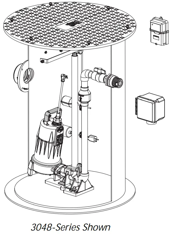
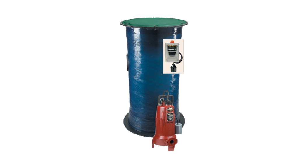
Simplex Grinder Systems
2 4 4 8 – Ser i es
- 24″ D X 48″ H Fiberglass Basin
3 0 3 6 – Ser i es
- 30″ D X 36″ H Fiberglass Basin
3 0 4 8 – Ser i es
- · 30″ D X 48″ H Fiberglass Basin
Features
- LSG202M Grinder Pump (2 hp, 208/ 230V)– or
- LSGX202M Grinder Pump (2 hp, 208230V)
- GR20 Guide Rail System
- Plugger Box
- Alarm
IMPORTANT: All Liberty Pumps products are supplied with their own separate Installation/ Operation/ Maintenance manuals. Ensure receipt of these manuals, and that they are read and understood prior to installation. For questions, call Liberty Pumps customer service at 800-543-2550.
7000 Apple Tree AvenueBergen, NY 14416ph: 800-543-2550fax: 585-494-1839www.LibertyPumps.com
Keep this manual handy for future reference.For replacement manual, visit LibertyPumps.com, or contact Liberty Pumps at 800-543-2550.Retain dated sales receipt for warranty.
![]() Installer: Manual must remain with owner or system operator/ maintainer.
Installer: Manual must remain with owner or system operator/ maintainer.
Prior to installation, record information from the pump nameplate for future reference:
System:—————————-Model(s):————————–Serial(s):————————–Control Panel:——————-M FG Date:———————Install Date:———————
Safety Guidelines
 |
This safety alert symbol is used in the manual and on the pump to alert of potential risk for serious injury or death. |
 |
This safety alert symbol identifies the risk of electric shock. It is accompanied by an instruction intended to minimize the potential risk of electric shock. |
 |
This safety alert symbol identifies the risk of fire. It is accompanied by an instruction intended to minimize the potential risk of fire. |
 |
This safety alert symbol identifies the risk of serious injury or death. It is accompanied by an instruction intended to minimize the potential risk of injury or death. |
| Warns of hazards which if not avoided will result in serious injury or death. | |
| Warns of hazards which if not avoided could result in serious injury or death. | |
| Warns of hazards which if not avoided could result in minor or moderate injury. | |
|
Signals and important instructions related to the pump. Failure to follow these instructions could result in pump failure or property damage. |
|
|
Read every supplied manual before using the pump system. Follow all the safety instructions in manual(s) and on the pump. Failure to do so could result in serious injury or death. |
Safety Precautions
![]() RISK OF ELECTRIC SHOCK
RISK OF ELECTRIC SHOCK
- Accidental contact with electrically live parts, items, fluid, or water can cause serious injury or death.
- Always disconnect pump(s) from a power source(s) before handling or making any adjustments to either the pump(s), the pump system, or the control panel.
- All installation and maintenance of pumps, controls, protection devices, and general wiring shall be done by qualified personnel.
- All electrical and safety practices shall be in accordance with the National Electrical Code®, the Occupational Safety and Health Administration, or applicable local codes and ordinances.
- Do not remove cord and strain relief, and do not connect conduit to pump.
- The pump shall be properly grounded using its supplied grounding conductor. Do not bypass grounding wires or remove the ground prongs from attachment plugs. Failure to properly ground the pump system can cause all metal portions of the pump and its surroundings to become energized.
- Do not handle or unplug the pump with wet hands, when standing on damp surfaces, or in water unless wearing Personal Protective Equipment.
- Always wear dielectric rubber boots and other applicable Personal Protective Equipment (PPE) when water is on the floor and an energized pump system must be serviced, as submerged electrical connections can energize the water. Do not enter the water if the water level is higher than the PPE protection or if the PPE is not watertight.
- Do not lift or carry a pump or a float assembly by its power cord. This will damage the power cord and could expose the electrically live wires inside the power cord.
- The electrical power supply shall be located within the length limitations of the pump power cord, and for below-grade installations, it shall be at least 4 ft (1.22 m) above floor level.
- Do not use this product in applications where human contact with the pumped fluid is common (such as swimming pools, fountains, marine areas, etc.).
- Protect the power and control cords from the environment. Unprotected power and control (switch) cords can allow water to wick through ends into pump or switch housings, causing surroundings to become energized.
- Single-phase 208/ 230V pumps shall only be operated without the float switch by using the circuit breaker or panel disco neat.
- Some products may have internal capacitors that could cause shock. Avoid contact with plug ends after removing from the energy source.
![]() RISK OF FIRE
RISK OF FIRE
- Do not use an extension cord to power the product. Extension cords can overload both the product and extension cord supply wires. Overloaded wires will get very hot and can catch on fire.
- This product requires a separate, properly fused, and grounded branch circuit, sized for the voltage and amperage requirements of the pump, as noted on the nameplate. Overloaded branch circuit wires will get very hot and can catch on fire. When used, electrical outlets shall be simplex of the appropriate rating.
- Do not use this product with or near flammable or explosive fluids such as gasoline, fuel oil, kerosene, etc. If rotating elements inside the pump strike any foreign object, sparks
- Sewage and effluent systems produce and may contain flammable and explosive gases. Prevent the introduction of foreign objects into the basin as sparks could ignite these gases. Exercise caution using tools and do not use electronic devices or have life, exposed electrical circuits in or around basins, open covers, and vents.
- These pumps are not to be installed in locations classified as hazardous in accordance with the National Electric Code®, ANSI/NFPA 70.
![]() RISK OF SERIOUS INJURY OR DEATH
RISK OF SERIOUS INJURY OR DEATH
- Energizing the control panel or breaker for the first time is potentially dangerous. Licensed electrical personnel should be present when the panel or breaker is energized for the first time. If faults caused by damage or poor installation practices have not been detected, serious damage, injury or death can result when power is applied.
- Do not modify the pump/pump system in any way. Modifications may affect seals, change the electrical loading of the pump, or damage the pump and its components.
- All pump/pump system installations shall be in compliance with all applicable Federal, State, and Local codes and ordinances.
- Do not allow children to play with the pump system.
- Do not allow any person who is unqualified to have contact with this pump system. Any person who is unaware of the dangers of this pump system, or has not read this manual, can easily be injured by the pump system.
- In 208/230V installations, one side of the line going to the pump is always “hot”, whether the float switch is on or off. To avoid hazards, install a double pole disconnect near the pump installation.
- Vent basin in accordance with local code. Proper venting of sewer and effluent gases alleviates the poisonous gas buildup and reduces the risk of explosion and fire from these flammable gases.
- Wear adequate Personal Protective Equipment when working on pumps or piping that have been exposed to wastewater. Sump and sewage pumps often handle materials that can transmit illness or disease upon contact with skin and other tissues.
- Do not enter a pump basin after it has been used. Sewage and effluent can emit several gases that are poisonous.
- Do not remove any tags or labels from the pump or its cord.
- Keep clear of suction and discharge openings. To prevent injury, never insert fingers into the pump while it is connected to a power source.
- Do not use this product with flammable, explosive, or corrosive fluids. Do not use in a flammable and/or explosive atmosphere as serious injury or death could result.
- This product contains chemicals known to the State of California to cause cancer and birth defects or other reproductive harm. www.p65warnings.ca.gov.
- A grinder pump contains metal parts that rotate at high speeds. Be careful around the pump base while power is connected. Make sure that the pump is either in the tank orclear from people and wires when in operation.
![]()
- Verify a Redundant Check Valve Assembly (curb stop and check valve) is installed between the pump discharge and the street main, as close to the public right-of-way as possible, on all installations to protect from system pressures.
- Do not dispose of materials such as paint thinner or other chemicals down drains. Doing so could chemically attack and damage pump system components and cause product malfunction or failure.
- Do not use these pumps with fluid over 140°F (60°C). Operating the pump in fluid above this temperature can overheat the pump, resulting in pump failure.
- Do not use a pump system with mud, sand, cement, hydrocarbons, grease, or chemicals. Pump and system components can be damaged from these items causing product malfunction or failure. Additionally, flooding can occur if these items jam the impeller or piping.
- Do not run dry.
- The Uniform Plumbing Code®states that sewage systems shall have an audio and visual alarm that signals a malfunction of the system, to reduce the potential for property damage.
- Do not exert heavy pressure or run heavy equipment on the backfill material as this could cause the tank to collapse.
Introduction
Pump, alarm, and plugger boxes are supplied with their own separate Installation/Operation/Maintenance manuals. Ensure receipt of these manuals, and that they are read and understood prior to installing and using this system. Familiarity with the pump, alarm, and plugger box is critical.
This manual provides a brief overview of the system and deals mainly with the inspection and installation of the basin. It does not cover the specifics of the pump, alarm, and plugger box operation. For questions, call Liberty Pumps customer service at 800-543-2550.
Identification
Information about the system can be found on a tag located on the basin cover. This identifies the system model number as well as the horsepower, voltage, and amp draw for the pump. Pump tags are located on the pump. Duplicate pump tags are packaged with the system. These should be mounted on the basin cover orat the plugger box for accessibility and specific pump information.
Inspection
Inspect the system upon arrival to ensure that there is no shipping damage. Pay careful attention to the condition of the fiberglass basin, control floats, pump guide rail brackets, and plugger box. Notify the carrier immediately if there is any damage. Read all instructions and become familiar with the system’s operation prior to proceeding with the installation.
Model Specifications
For a complete listing of pump models and their specifications, refer to http://www.LibertyPumps.com/About/Engineering-Specs. The pump nameplate provides a record of specific pump information.
Basin Installation
This is a brief reference to the recommended methods and procedures for installing Liberty Pumps basins to ensure that damage or premature failure of the basin does not occur.
This section is not intended to serve as a basic instructional guide. The installation of Liberty Pumps sump and sewage basins is a specialized skill and is assumed that the individuals who install our products and refer to this section will have a basic understanding of such procedures as excavating, backfilling, pipefitting, and electrical work. No amount of written instruction by the manufacturer or regulatory agency will convert an inexperienced, under-supervised laborer into a skilled, experienced mechanic. The ability to recognize and correctly respond to abnormal conditions during a basin installation requires field experience as well as mechanical aptitude. Figure 1 is provided for reference. In addition to proper system engineering and competent manufacturing, the use of basin installers who have both practical experience and integrity to assist that the basin is installed properly constitutes the greatest protection from catastrophic basin failure and liability exposure.
Basin Handling
General HandlingAlthough the exterior surfaces of the fiberglass basins are designed to withstand normal handling, they can be damaged during transportation and installation. Basins must not be dropped, dragged, or handled with sharp objects, and with the exception of the minimal movement involved in a visual inspection, must not be rolled.
Unloading, Lifting, and Lowering
- Under no circumstances is the use of chains or cables around the basin shell permitted.
The proper way to move a basin is by lifting it, using chains or cables with the optional lifting lugs (not more than a 30° angle), or by using a non-marring sling around the basin. Before any attempt is made to move a basin, verify that all equipment and accessories have sufficient capacity and reach to lift and lower the basin without dragging and/or dropping. Maneuver the basin with guide ropes attached to the sides.
Pre-Installation Inspection
Confirm adherence to the project’s specifications before installation. Physically and visually inspected basin, pumps, valves, equipment, and piping materials before installation. Notify the carrier immediately if there is any damage. If the basin or any of its internal components are damaged, suspend installation until a determination of the extent of damage can be made by Liberty Pumps or its agent. Any repairs must be first authorized in writing by Liberty Pumps and then be done in accordance with Liberty Pumps instructions.
Storage
Store the basin in a secure, controlled area where the potential for accidental damage or vandalism will be minimized. The storage area must be free from sharp objects, rocks, and any other foreign solutions or materials that could cause damage to the basin. Chock the basin until it is needed for installation and, if windy conditions are possible, secure the basin with non-marring restraints of size and number adequate for securing the basin. Excavation
- Locate all overhead and underground utilities before excavating.
Excavation Considerations
The excavation must provide adequate space for the basin, piping, and other buried equipment, and for the replacement and compaction of backfill materials particularly around the basin walls. The size, shape, and wall slope of the excavation should be determined by soil conditions, depth of excavation, shoring requirements, and if workers are required to enter the excavation, safety considerations, and federal, state, county, and municipal regulations.
Excavation Location
Excavation for an underground basin must be made with due care to avoid undermining foundations of existing structures and contact with underground utilities. In the absence of building codes or regulations, maintain a minimum distance of 5 feet plus a slope of 45° from the bottom of the compacted sub-base to the bottom of the adjacent structures, foundations, footings, and property lines. Additional distances may be required to ensure that any loading carried or created by the foundations and supports cannot be transferred to the basin.
Maximum Basin Burial Depth
If burial depth is greater than the basin height, contact Liberty Pumps to determine if additional wall reinforcement is required and secure written authorization.
Excavated Materials Handling
Carefully store excavated materials, that cannot be removed from the job site, as far from the edge of the basin excavation as possible. Unless approved for use as a backfill, securely store excavation materials separate from the approved backfill materials.
Work Area SafetySafe installation procedures are the sole responsibility of the basin installer. Work safety requirements are defined in US Department of Labor 29 CFR 1926, Subpart P: Excavations.
Backfill
Careful selection, placement, and compaction of approved backfill material are critical to a successful basin installation. Among the common problems associated with basin leaks and premature failures are:
- Use of incorrect backfill material
- Inadequate or improper placement or compaction
- Rocks, clods, or debris left in the excavation or basin
- Voids under or around the perimeter of the basin
- Failure to prevent the migration of backfill materials
Basin Placement
- Placement of a basin on a concrete pad or compacted sub-base smaller than the total basin bottom area or on intermediate supports (saddles) will cause uneven distributionof loads. This may contribute to structural failure and is never permitted.
Cover the bottom of the basin excavation with suitably graded, leveled, and compacted backfill material to a depth of at least 12” (compacted sub-base). If a concrete hold-down/anti-flotation pad is required, this bedding can be reduced to a depth of at least 6”. Carefully lower the basin into the excavated area and center on the compacted backfill or concrete pad.
Backfill MaterialEnsure backfill material is clean, well granulated, free-flowing, non-corrosive, and inert; free of ice, snow, debris, rock, or organic material, all of which could damage the basin and interfere with the compaction of the backfill material. The largest particles shall not be larger than 3/4”. Not more than 3% (by weight) should pass through a #8 sieve, and the backfill material must conform to ASTM C-33, Paragraph 9.1 requirements. Approved backfill materials include:
- Pea gravel, naturally rounded particles, with a minimum diameter of 1/8” and a maximum diameter of 3/4”
- Crushed rock, washed and free-flowing angular particles between 1/8” and 1/2” in size
Backfill Placement and Compaction
![]()
- Do not exert heavy pressure or run heavy equipment on the backfill material as this could cause the tank to collapse.
Compaction of backfill materials must be adequate to ensure the support of the basin and to prevent movement or settlement. Place backfill materials in 12” lifts and compact to a minimum soil modulus of 700 pounds per square foot.
Support Piping, Equipment, and Accessories
- Using the basin to support any loading carried or created by piping, equipment, cribbing, bracing, or blocking is never permitted.
Provide support for piping, equipment, and other accessories during backfilling. During backfilling, temporary support must be carefully installed and removed to prevent damage to the basin, piping, and/or equipment.
Anchorage
When basin installations are located in areas subject to high water tables or flooding, make provisions to prevent the basin, either empty or filled, from floating. The buoyancy force to be offset is determined primarily by the volume of the basin. The principle offsetting factors include:
- Backfill materials
- Concrete hold-down pad
- Friction between the basin, backfill materials, and surrounding soil
Anchorage Methods
All methods of anchoring the basin use the weight of the backfill materials to offset the buoyancy forces. The use of supplemental mechanical anchoring methods (i.e., a concrete hold-down pad) increases the amount of backfill ballast that is mechanically attached to the basin. The recommended method of attachment is to pour concrete grout over the basin’s anti-flotation flange and concrete hold-down pad. Anchorage Requirements
- Use “submerged” material weights when calculating anchorage requirements.
Requirements of anchorage, the thickness of concrete hold-down pads, as well as the size of anchors and reinforcement, must be calculated for each installation based on the environmental conditions of the specific installation.
Example: weight of concrete (150 pounds per cubic foot) minus the weight of the water (62.4 pounds per cubic foot) equals a “submerged” weight of 87.6 pounds per cubic foot.

NOTE: The intent of these installation instructions and illustrations is to ensure that damage or premature failure to the basin does not occur. These installation instructions and illustrations are not intended to preclude normal safety procedures that should be followed to prevent injury to personnel.
SAFE INSTALLATION PROCEDURES ARE ENTIRELY THE RESPONSIBILITY OF THE INSTALLER
Figure 1. Basin Installation Reference
Installation
![]() RISK OF ELECTRIC SHOCK
RISK OF ELECTRIC SHOCK
- All installation and maintenance of pumps, controls, protection devices, and general wiring shall be done by qualified personnel.
- All electrical and safety practices shall be in accordance with the National Electrical Code®, the Occupational Safety and Health Administration, or applicable local codes and ordinances.
Electrical Connections
With main power disconnected, complete pump and plugger box connections per plugger box wiring diagrams. Verify connections. When complete, check all wires for unintentional ground.
Discharge Line
Connect schedule 80 PVC pipes to pump discharge. Do not increase discharge piping to larger than 2”. Do not reduce discharge to below the pump outlet size. The remainder of the discharge line should be as short as possible with a minimum number of turns to minimize friction head loss.
Alarm and Plugger Box
Connect the alarm panel and plugger box per their own Installation manuals.Connect pump and float switch leads to the plugger box in accordance with the instructions included with the unit.
Inlet Line
Connect the inlet line to the inlet hub per the engineer’s specifications.
Vent
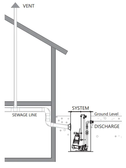
The basin must be completely sealed and properly vented per local health and plumbing code requirements. The system is designed to be vented through the inlet to an existing building vent stack. In order to accomplish this, there must be no traps between the system inlet and the nearest building vent stack connection. If this is not possible or desirable per the application, a vent flange or grommet can be installed in a hole cut into the cover.
Float Switches
Float switches are pre-mounted on a QuickTree®. For QuickTree removal, loosen the cord nut, locking clamp, and pull the QuickTree straight out of the basin.
The pump cycle is preset at the factory. The pump cycle can be adjusted by loosening the cord grip and moving the ON/OFF float up or down. Adjustments of more than 3″ in either direction are not recommended—call customer service if the pump cycle needs to be adjusted beyond this recommended level. The preset pump levels are provided in Table 1.
Table 1. Factory Set Float Switch Levels
| System | OFF | ON | ALARM |
| 2448 | 9-1/2” | 16-1/2” | 21” |
| 3036 | 9-1/2” | 16-1/2” | 21” |
| 3048 | 9-1/2” | 16-1/2” | 21” |
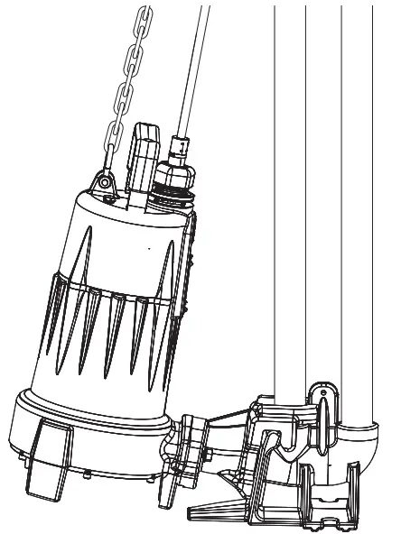
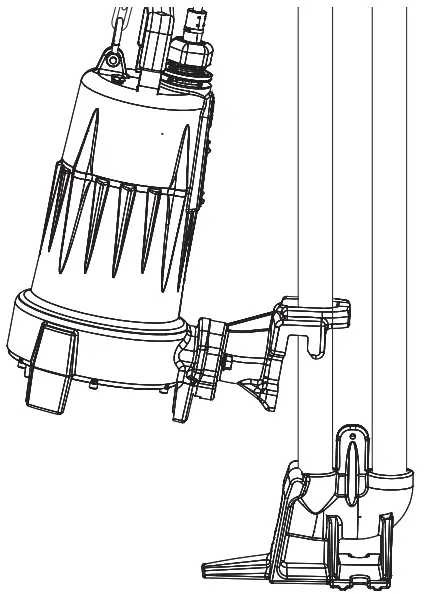
GR-Series Guide Rail System
The GR20 quick-disconnect assembly guide rail system provided with the system is designed to allow easy installation and removal of the pump. When installed correctly, it will seal and provide a means to lift the pump without disconnecting any of the discharge piping. Ensure installation is done as shown.
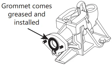 |
 |
|
Guide Rail Base |
Grommet Location |
 |
 |
|
Operating Position |
Disconnected Position |
The operation, Maintenance, and Troubleshooting
Refer to supplied pump, alarm, and plugger box manuals. For further questions, contact customer service at 800-543-2550 or [email protected].
Warranty
Liberty Pumps Wholesale Products Limited Warranty
Liberty Pumps, Inc. warrants that Liberty Pumps wholesale products are free from all factory defects in material and workmanship for a period of three (3) years from the date of purchase (excluding batteries). The date of purchase shall be determined by a dated sales receipt noting the model and a serial number of the pump. The dated sales receipt must accompany the returned pump if the date of return is more than three years from the date of manufacture noted on the pump nameplate.
The manufacturer’s sole obligation under this Warranty shall be limited to the repair or replacement of any parts found by the manufacturer to be defective provided the part or assembly is returned freight prepaid to the manufacturer or its authorized service center, and provided that none of the following warranty-voiding characteristics are evident:
The manufacturer shall not be liable under this Warranty if the product has not been properly installed, operated, or maintained per manufacturer instructions; if it has been disassembled, modified, abused, or tampered with; if the electrical cord has been cut, damaged, or spliced; if the pump discharge has been reduced in size; if the pump has been used in water temperatures above the advertised rating; if the pump has been used in water containing sand, lime, cement, gravel, or other abrasives; if the product has been used to pump chemicals, grease, or hydrocarbons; if a non-submersible motor has been subjected to moisture; or if the label bearing the model and the serial number has been removed.
Liberty Pumps, Inc. shall not be liable for any loss, damage, or expenses resulting from installation or use of its products, or for indirect, incidental, and consequential damages, including costs of removal, reinstallation, or transportation.
There is no other express warranty. All implied warranties, including those of merchantability and fitness for a particular purpose, are limited to three years from the date of purchase. This Warranty contains the exclusive remedy of the purchaser, and, where permitted, liability for consequential or incidental damages under any and all warranties are excluded.
 report this ad
![]()
7000 Apple Tree AvenueBergen, NY 14416ph: 800-543-2550fax: 585-494-1839www.LibertyPumps.comCopyright © Liberty Pumps, Inc. 2020 All rights reserved.7386000M
References
[xyz-ips snippet=”download-snippet”]