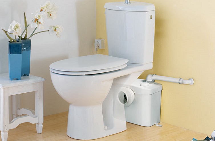
Liberty Pumps Ascent II-ESW Complete System with Round Front Toilet

Models
Ascent II-ESW Complete System with Elongated ToiletAscent II-RSW Complete System with Round Front Toilet
NOTICE: Installer: Manual must remain with owner/operator.
7000 Apple Tree AvenueBergen, NY 14416ph: 800-543-2550fax: 585-494-1839www.LibertyPumps.com
Keep this manual handy for future reference.For replacement manual, visit LibertyPumps.com or contact Liberty Pumps at 800-543-2550.Retain dated sales receipt for warranty.
Safety Guidelines
|
|
This safety alert symbol is used in the manual and on the pump to alert of potential risk for serious injury or death. |
|
|
This safety alert symbol identifies risk of electric shock. It is accompanied with an instruction intended to minimize potential risk of electric shock. |
|
|
This safety alert symbol identifies risk of fire. It is accompanied with an instruction intended to minimize potential risk of fire. |
|
|
This safety alert symbol identifies risk of serious injury or death. It is accompanied with an instruction intended to minimize potential risk of injury or death. |
| DANGER | Warns of hazards which, if not avoided, will result in serious injury or death. |
| WARNING | Warns of hazards which, if not avoided, could result in serious injury or death. |
| CAUTION
|
Warns of hazards which, if not avoided, could result in minor or moderate injury. |
| NOTICE | Signals an important instruction related to the pump. Failure to follow these instructions could result in pump failure or property damage. |
WARNING: Read every supplied manual before using pump system. Follow all the safety instructions in manual(s) and on the pump.Failure to do so could result in serious injury or death.
Safety Precautions
WARNING: RISK OF ELECTRIC SHOCK
- Accidental contact with electrically live parts, items, fluid, or water can cause serious injury or death.
- Always disconnect pump (macerator) from power source before handling or making any adjustments. Fatal electrical shock could occur.
- The pump shall be plugged into a properly fused electrical outlet with a ground fault circuit interrupter (GFCI) that conforms to current National Electric Code (NEC) and all applicable local codes. All wiring must be performed by qualified personnel.
- All electrical and safety practices shall be in accordance with the National Electrical Code®, the Occupational Safety and Health Administration, or applicable local codes and ordinances.
- Pump shall be properly grounded using its supplied grounding conductor. Do not bypass grounding wires or remove ground prong from attachment plugs. Failure to properly ground the pump system can cause all metal portions of the pump and its surroundings to become energized.
- Do not handle or unplug pump with wet hands, when standing on a wet/damp surface, or in water. Fatal electrical shock could occur.
- Do not lift or carry the pump by its power cord. This will damage the power cord, and could expose the electrically live wires inside the power cord.
- The electrical power supply shall be located within the length limitations of the pump power cord, and for below grade installations it shall be at least 4 ft (1.22 m) above floor level.
- Do not submerge macerator or allow macerator to be exposed to water. Macerating toilet system is acceptable for indoor dry location use only. Serious injury or death could result.
WARNING: RISK OF FIRE
- Do not use an extension cord to power the product. Extension cords can overload both the product and extension cord supply wires. Overloaded wires will get very hot and can catch on fire.
- Explosion hazard during installation. PVC cleaners, primers, and cements can release explosive vapors. These heavier-than-air vapors can accumulate in the tank. The heat of soldering or sweating copper or other metal pipe can ignite these vapors causing a violent explosion. If the unit is to be connected to copper discharge or vent piping, all solvent-welded PVC joints must be allowed to cure a minimum of 24 hours. The access cover must be removed to allow the tank to be thoroughly ventilated prior to sweating copper pipe near the unit.
- These pumps are not to be installed in locations classified as hazardous in accordance with the National Electric Code®, ANSI/NFPA 70.
WARNING: RISK OF SERIOUS INJURY OR DEATH
- Do not modify the pump/pump system in any way. Modifications may affect seals, change the electrical loading of the pump, or damage the pump and its components.
- All pump/pump system installations shall be in compliance with all applicable Federal, State, and Local codes and ordinances.
- Do not remove any tags or labels from the pump or its cord.
- Keep clear of suction and discharge openings. To prevent injury, never insert fingers into pump while it is connected to a power source.
- The macerator has a large opening to accept the discharge hub of a rear discharge toilet. Do not place hand or other objects into this opening even if unit is unplugged. The macerator has razor sharp cutters within this opening.
- Decorative covers must be installed for operation as a safety device is integrated into the covers to prevent unintended operation. The unit may start when energized the first time.
- This product contains chemicals known to the State of California to cause cancer and birth defects or other reproductive harm. www.p65warnings.ca.gov
CAUTION
- This pump has been evaluated for use with water only.
- Wear Protective Personal Equipment to protect hands as exposed cutter blades have sharp edges.
NOTICE
- Do not use pumps with fluid over 104°F (40°C). Operating the pump in fluid above this temperature can overheat the pump, resulting in pump failure.
- Do not use an air admittance valve or a mechanical spring-loaded venting device, as these devices are one-way valves. The air pressure in and outside the macerating pump unit must be equal and a “cheater” vent will obstruct the airflow in one direction and prevent proper toilet function.
- The Ascent II macerating unit includes electronic controls and must be protected from direct water exposure during installation and use.
- Sanitary fixtures connected to the macerating system must be located on the same floor level.
Introduction
Before installation, read the following instructions carefully. Each Liberty Pumps product is individually factory tested to ensure proper performance. Closely following these instructions will eliminate potential operating problems, assuring years of trouble-free service.No repair work should be carried out during the warranty period without prior factory approval. Any unauthorized repairs void warranty. Contact Liberty Pumps at 1-800-543-2550.
Inspection and Storage
Initial Inspection
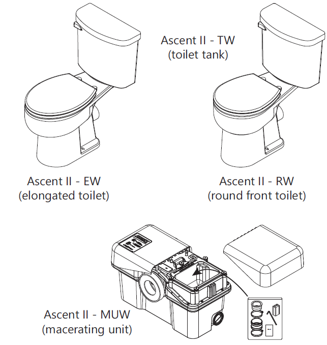
The Ascent II Macerating Toilet System is shipped in three separate packages: the toilet tank, toilet bowl, and macerating unit. The shipping containers should be immediately inspected for damage that may have occurred in shipment.
- Visually check the macerating unit and any spare parts for damage.
- Check for damaged electrical wires, especially where they exit the macerating tank.
- Check all packaging for spare parts before discarding.Contact Liberty Pumps customer service to report any damage or shortage of parts.
List of included parts:
- Toilet Tank (model: Ascent II – TW)
- Toilet Bowl (model: Ascent II – RW or EW)
- Macerator (model: Ascent II – MUW)
- Macerator tank
- Rubber couplings with clamps
- Reducing bushings
- 9V battery
- 3/16” Allen wrench
- Grease packet
Storage Before Use
Liberty Pumps products are shipped from the factory ready for installation and use. If storage is necessary, the pump should remain in its shipping container. It should be stored in a warehouse or other area that is clean, dry and temperature-stable.The pump and packaging should be covered to protect it from water, dirt and dust.
General Information
The macerator is designed to accept wastewater from a rear discharge toilet but can also simultaneously receive wastewater from several sanitary fixtures such as a sink, shower, bathtub, or urinal (a single bathroom group). However, only one water closet (toilet) per unit may be connected.
UsageThe macerating system is designed for the disposal of human waste, toilet paper, and water. It is not intended for kitchen waste, nor is it intended to be used for the disposal of wastewater from such pumped appliances as dishwashers and clothes washers. This product is not designed for emptying large pools or spas.The macerating system starts automatically once the toilet is flushed or liquid from other fixtures enters the unit. It automatically shuts off once the contents have been pumped away. Run times will vary depending on inflow and source.
Features
- Improved cutter design with RazorCut™ system. The cutter blades are designed and rigorously tested to last indefinitely without need for service or replacement in ordinary applications.
- The CleanConnect™ Seal allows the macerator to sit closer to the toilet.
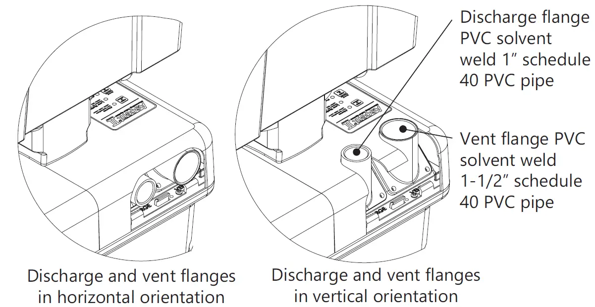
- QuickFlip™ discharge and vent connectors allow for horizontal or vertical pipe connections.
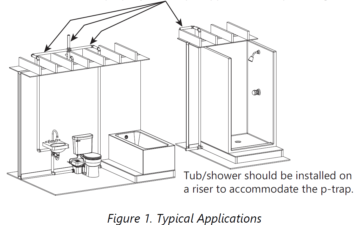
Bath LayoutSanitary fixtures connected to the macerating system must be located on the same floor level.
The toilet works as a conventional flushing toilet and needs no special maintenance with normal use.Any regular bathtub (up to 100 gallons) or shower can be used.When installing these fixtures, build a 6 inch high platform for the fixture to be placed. This provides enough space for a p-trap and slope toward the macerator auxiliary inlets. When installing a shower, manufacturers sometimes offer a prefabricated raised shower base. Note: The actual distance between the p-trap of the additional fixture and macerator determines the necessary clearance to install the p-trap and elevation required to ensure a minimum pitch of 1/4” per foot drop.
Normal Operating Cycle
The macerator controls are capable of distinguishing between different modes of operation and optimizes the run time accordingly.Advanced run detection will energize the cutters once the unit detects a flush. In doing so, the cutters are spinning at maximum speed (rpm) prior to fluid and debris reaching the cutting system. The unit may pulse during a shower or draining a bathtub because the macerator can pump at a higher rate than the incoming flow.
Use and Care
All standard cleaners can be used just as with a standard conventional toilet. The exterior of the macerating unit may be cleaned with a damp cloth and normal household cleaners. Never spray or dump water or chemicals directly on the unit.
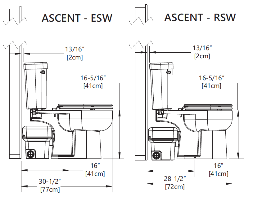
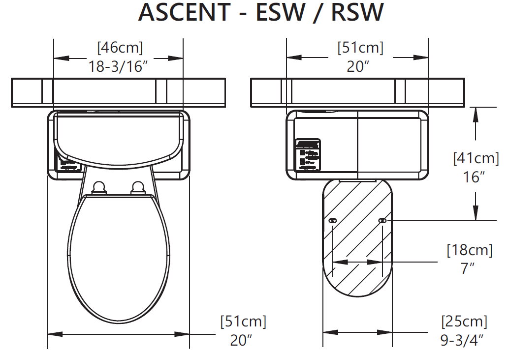
Dimensional Data
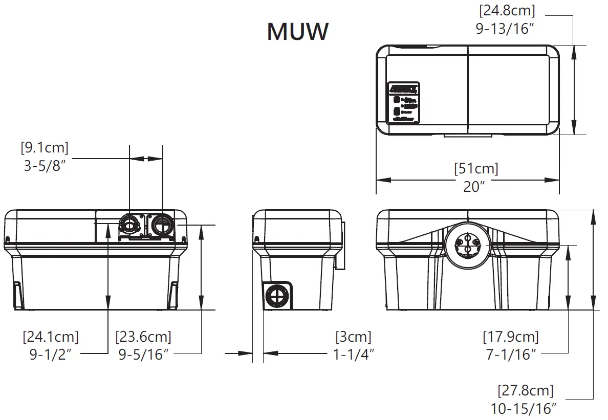
Macerating Unit
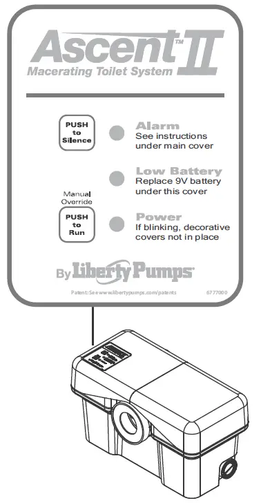
User InterfaceThe macerator has a user interface (touchpad with LEDs) located on the top left side of the unit.
This interface has three LEDs:ALARM: unit is unable to evacuate the holding tank or cannot keep up with the incoming flow. Audible alarm also activates.LOW BATTERY: 9V battery needs to be replaced.POWER: unit has power.
The interface also has two pushbuttons:PUSH to Silence: silences the audible alarm.PUSH to Run: overrides the internal switch to manually run the macerator and pump.
AlarmThe macerator has an integral alarm that will sound if the unit cannot remove liquid or keep up with incoming water. If the alarm sounds, a number of conditions could exist. Refer to the Troubleshooting section to determine the cause and solution.A silence button located on the user interface touchpad stops the audible alarm. The red alarm LED will continue to illuminate. Discontinue using the product until the problem has been identified and resolved.
IMPORTANT: In the event of a power outage, a 9V battery will power the alarm, and if necessary, the macerator will accept two flushes prior to alarm activation. After that, the unit should not be used again until the power is restored. The alarm automatically resets once a normal cycle is performed.
Low BatteryIf the yellow LED is illuminated, the 9V battery needs to be replaced. The expected life of the supplied battery is 5 to 7 years.
PowerThe LED will be green when power is applied, but LED must be steady to operate. Both decorative covers must be properly in place to engage safety switch.
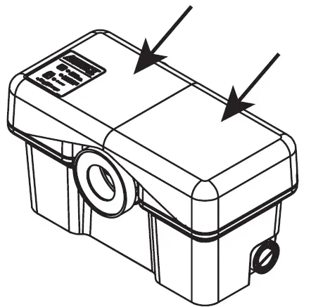
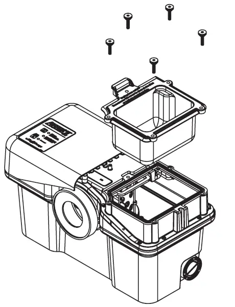
Decorative CoversThe decorative covers are shipped from the factory assembled on the unit. However, during the installation both covers must be removed from the macerator.
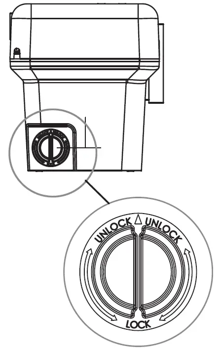
Battery AccessThe battery receptacle is accessible under the left decorative cover. Do not install battery until the unit has been installed, connected, and ready for operation.

Auxiliary InletsThe macerator unit is equipped with two inlet ports, one on each side.These ports are designed for standard PVC pipe. Included with the system are two 2” flexible PVC couplers and 1-1/2” reducing bushings. These inlets, which incorporate an internal check valve, are used to connect the drainpipe of other sanitary fixtures to the macerating pump unit.Typically, the 2” drain is used with shower stalls only. A tub, shower/tub combo, or sink would use a 1-1/2” drain line. From the factory, the auxiliary inlets are plugged; if the port is to be used, the plug must be removed by rotating until the rib is vertical and then pulling outward. If the unit has been stored for some time, pliers may be needed to assist in removal.
Access CoverThe macerator has an access cover that can be removed to gain access to the pumping and macerating cartridge to remove debris or perform service. The auxiliary inlet couplers, Allen wrench, grease packet, clamps, and 9V battery are shipped in the access cover beneath the right access cover.
Preparation
WARNING: RISK OF ELECTRIC SHOCK
- The pump shall be plugged into a properly fused electrical outlet with a ground fault circuit interrupter (GFCI) that conforms to current National Electric Code (NEC) and all applicable local codes. All wiring must be performed by qualified personnel.
- Pump shall be properly grounded using its supplied grounding conductor. Do not bypass grounding wires or remove ground prong from attachment plugs. Failure to properly ground the pump system can cause all metal portions of the pump and its surroundings to become energized.
- The electrical power supply shall be located within the length limitations of the pump power cord, and for below grade installations it shall be at least 4 ft (1.22 m) above floor level.
WARNING: RISK OF FIRE
- Do not use an extension cord to power the product. Extension cords can overload both the product and extension cord supply wires. Overloaded wires will get very hot and can catch on fire.
- Explosion hazard during installation. PVC cleaners, primers, and cements can release explosive vapors. These heavier-than-air vapors can accumulate in the tank. The heat of soldering or sweating copper or other metal pipe can ignite these vapors causing a violent explosion. If the unit is to be connected to copper discharge or vent piping, all solvent-welded PVC joints must be allowed to cure a minimum of 24 hours. The access cover must be removed to allow the tank to be thoroughly ventilated prior to sweating copper pipe near the unit.
WARNING: RISK OF SERIOUS INJURY OR DEATH
- Do not modify the pump/pump system in any way. Modifications may affect seals, change the electrical loading of the pump, or damage the pump and its components.
- All pump/pump system installations shall be in compliance with all applicable Federal, State, and Local codes and ordinances.
NOTICE: Macerating unit must be located on same floor as connecting fixtures.
Layout: The bathroom layout should be designed prior to installation. Make certain the power source (GFCI receptacle) is within range of the macerator’s 8 ft power cord. The GFCI receptacle shall be 40 inches away (in a straight line) from a shower or bathtub. For basement installation, the receptacle shall be 48 inches from the floor.Power Cord: The power cord can be configured to exit the unit on either the left or right side. If the power cord will exit the left side of the macerator, the vent flange must be removed so the cord can be routed between the positioning clips. Reinstall vent flange after routing the cord. Do not use an extension cord. If the electrical power receptacle (outlet) is in close proximity to the macerator, any extra power cord can be coiled and tucked away in the access cover located under the right decorative cover.Easy Access: The unit should be accessible and removable in the event of required maintenance. During installation, a full port ball valve should be installed near the discharge flange to allow easy service of the unit. If possible, the right side of the macerator should remain unobstructed. The access cover allows access to the internal mechanisms. In the event of a jam, the decorative cover as well as the access cover will need to be removed from the macerator and working room to do so would be beneficial.Water Supply: The water supply line for the toilet tank is located on the left side. When roughing in, allow for the macerator.Discharge: Never discharge directly into an open drain, fixture, manhole or rainwater drainpipe. It is illegal, as it constitutes a health hazard. Only direct connections into sanitary waste systems shall be acceptable.
Auxiliary Ports: Auxiliary inlet ports are located on either side toward the back of the macerator tank. These ports can accept waste from sink or tub/shower. A sink should be plumbed into one of the auxiliary inlets and not the discharge line of the macerator even if elevations would allow such an installation. The discharge line is pressurized and the plumbing system needs to accommodate this.Freezing: Ensure all pipework susceptible to freezing is adequately insulated or heated. In unheated buildings, the toilet, piping, and macerating unit must be properly winterized. Use plumbing antifreeze or drain completely. The battery should also be disconnected.Discharge Extension: An optional discharge extension [P/N K001184 sold separately] allows the macerator to be positioned behind a wall. For example, the macerator could be positioned on the floor of a linen closet or utility room. Do not fully frame unit into a wall as access to macerator must be maintained.Toilet Placement: The toilet hold down fasteners should be located 16 inches from the wall and spaced 7 inches apart. This assumes a typical baseboard of 3/4” x 5-1/2” with 3/4” quarter round. Actual baseboard dimensions must be taken into account during the installation and thus rough-in dimensions may change.Tub/Shower: Water height will be 4½ inches in the macerator tank before the unit starts pumping. A shower stall floor must be well above this level. Liberty Pumps recommends at least 6–8 inches to ensure proper shower drainage and prevent any backflow.
All fixtures must be properly vented per applicable local plumbing code.
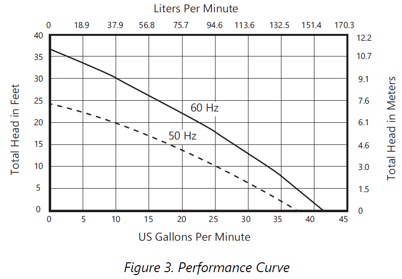
Pipework: All pipework should be copper, PVC, or CPVC. Do not use flexible piping. Support hangers should not be less than 4 ft apart to prevent pipe rattling.Pipe Supports: All sanitary pipework must be supported in accordance with the pipe manufacturer’s recommendations. Avoid dipping or trapping, which may cause the buildup of residual solids and subsequent blockage.Bends: Wherever possible, long sweeping bends should be used. Do not use short elbows. If sweeping 90° elbows are not available, use two 45° elbows to make a 90° turn.Shut-off Head: The macerator has a shut-off head of 36 ft. All frictional losses from horizontal runs and elbows need to be accounted for. The minimum flow rate for 1” PVC Schedule 40 pipe is 5 gal/min compared to 3 gal/min for 3/4” PVC pipe.Gravity Fall: The unit accepts wastewater by gravity; it does not vacuum in water. All inlet pipework must have a positive gravity fall (1/4 inch per foot drop minimum).Vertical Lift: If vertical lift is required, this must precede the horizontal pipe run. All vertical lifts should rise as close to the macerator as possible, allowing only for the need to clear the toilet tank. The initial horizontal run should not exceed 12 inches.Once the horizontal run is started, do not change directions in a vertical manner.Discharge: All discharge piping from the unit should run either directly vertical or in a horizontal plane (with a minimum 1/4 inch per foot drop) to the point of discharge. Pipework must not be installed with a diagonal upward slope from the unit to the point of discharge. Long downward pitched runs of discharge piping, or piping where the point of discharge is at a lower elevation than the macerator unit, should be designed to prevent siphoning from the macerator tank.Friction: Friction losses from horizontal runs without 1/4 inch per foot pitch will reduce the amount of vertical lift the system is capable of handling. Refer to Figure 3. Consult factory for proper sizing if there are long runs or multiple elbows.Lift Calculations: To pump vertically and horizontally, calculate 3 ft of vertical lift as equivalent to 30 ft of horizontal run. Each bend or change of direction gives a pressure drop, which must be calculated into the total head of the unit. As an estimate, reduce discharge height by 3 ft for each 90° bend.
For example: 1” Schedule 40 PVC pipe is used for the discharge and runs horizontally for 1 ft, then turns 90°, and rises 5 ft vertical. Then it travels horizontal with another 90° turn (3 turns in total) and connects with the soil-stack.Refer to Figure 2.
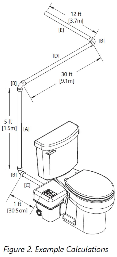
Calculations:[A] Total vertical lift 5 ft= 5 ft vertical[C+D+E] Total horizontal run 43 ft = 4.3 ft vertical[B] Total of three 90° elbows = 9 ft verticalAdd the three calculation totals together to get 18.3 ft of vertical head (lift). Referring to Figure 3, the application would result in a flow rate of 23 gal/min (60 Hz).
Macerating Unit PreparationAuxiliary inlets should be plumbed using the supplied auxiliary inlet couplings and/or reducing bushing when connecting to either 2” or 1-1/2” standard Schedule 40 PVC pipe. A plug must be removed by turning until the rib is vertical and pulling outward. Pliers may be required if unit has been stored.Both the discharge and vent flanges are shipped from the factory in the horizontal orientation. If the installation allows for a vertical orientation, the four screws must be removed from each in order to flip the flange. The decorative cover will need to be modified with the use of a hole saw and cutters to remove material. A template is provided on the underside of the decorative cover.
Installation
WARNING: RISK OF ELECTRIC SHOCK
- The pump shall be plugged into a properly fused electrical outlet with a ground fault circuit interrupter (GFCI) that conforms to current National Electric Code (NEC) and all applicable local codes. All wiring must be performed by qualified personnel.
- All electrical and safety practices shall be in accordance with the National Electrical Code®, the Occupational Safety and Health Administration, or applicable local codes and ordinances.
- Pump shall be properly grounded using its supplied grounding conductor. Do not bypass grounding wires or remove ground prong from attachment plugs. Failure to properly ground the pump system can cause all metal portions of the pump and its surroundings to become energized.
Note to Installer: During installation, it is best to cover the macerating unit with plastic to protect it from potential leaks at the toilet fill connection or tank to bowl gasket.
Refer to Figure 1 Typical Applications as needed during the installation process. Installations may vary per local plumbing and electrical codes. Also, discharge and vent pipe routing can vary per installation.
- Place the macerator in the desired location and connect all inlet and outlet waste piping to the unit. The inlet side should be facing the toilet to ensure proper placement. Refer to Figure 4 and Figure 5.
- Assemble the toilet in accordance with the installation manual(s) provided with it. Be careful when tightening fasteners as to not crack the porcelain.
- To mount the toilet to a concrete floor, drill two holes approximately 2-1/4” deep with a 5/16” masonry drill bit.Insert plastic plugs into holes. If the floor is wood, bore a pilot hole with a 1/4” drill bit. Fasteners not included.
- Toilet to macerator connection:
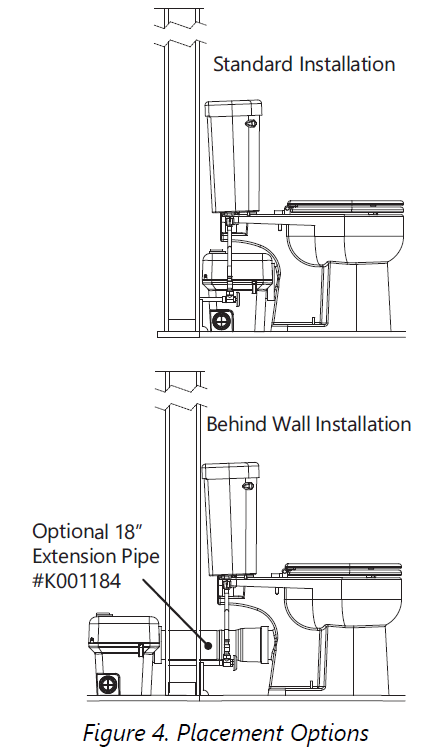
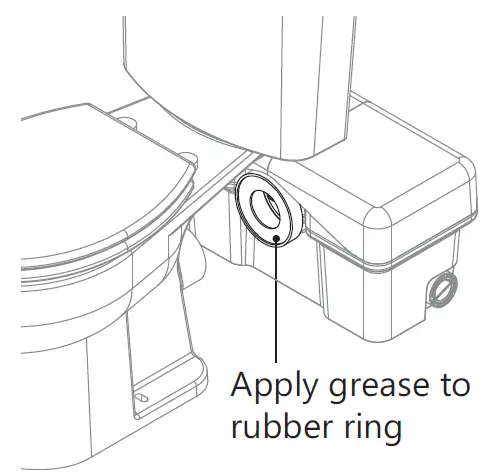
 a. Standard Installation:Place the toilet in front of the macerating tank and apply silicone grease (supplied) to the rubber sealing lip of macerator.Then slide the discharge hub of the toilet into the rubber sealing ring of the macerator.b. Behind Wall Installation:To install the macerator behind a wall, an Extension Pipe Kit (K001184, sold separately) is needed. Included in the kit are an 18-3/4” long extension pipe, a decorative trim ring, and a grease packet. Rubber rings seal both ends of the extension pipe. To prevent tearing, always grease both seals prior to installing the pipe. Slip the decorative trim ring onto the pipe. To install the pipe, no fasteners are required. Slip the extension pipe over the toilet discharge, and then insert the pipe into the macerator. Liberty Pumps recommends using only one extension pipe.
 - Place the toilet over the holes in the floor. Slip the plastic china protectors over the lag screws ensuring proper orientation. Tighten lag screws (do not overtighten) and snap plastic caps in place.For proper flushing performance, ensure that the base of the toilet is not below the base of the macerator. Check the extension pipe, if applicable, with a level, and verify that the pipe is either level or sloped toward the macerator unit and away from the toilet.
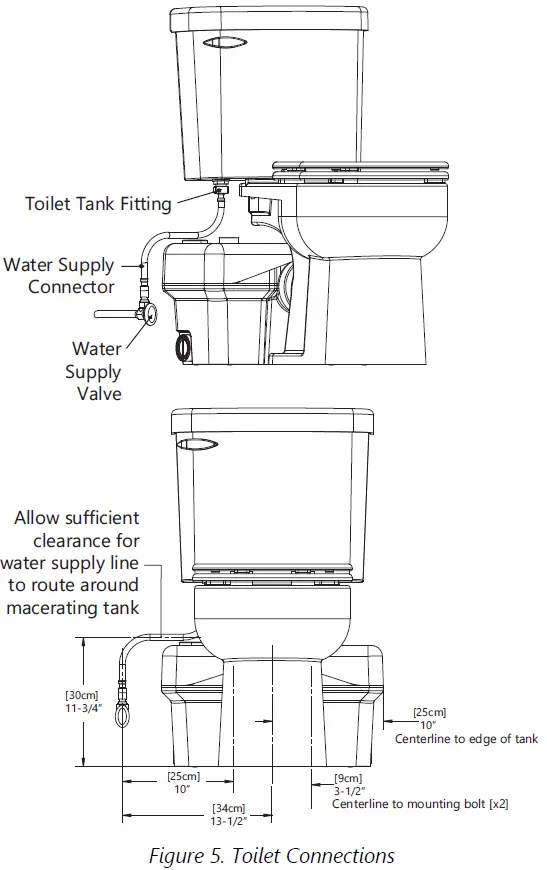
- Connect the water supply line to the fill valve, located directly below the flush lever, on the bottom of the toilet tank.
 a. Standard Installation:Place the toilet in front of the macerating tank and apply silicone grease (supplied) to the rubber sealing lip of macerator.Then slide the discharge hub of the toilet into the rubber sealing ring of the macerator.b. Behind Wall Installation:To install the macerator behind a wall, an Extension Pipe Kit (K001184, sold separately) is needed. Included in the kit are an 18-3/4” long extension pipe, a decorative trim ring, and a grease packet. Rubber rings seal both ends of the extension pipe. To prevent tearing, always grease both seals prior to installing the pipe. Slip the decorative trim ring onto the pipe. To install the pipe, no fasteners are required. Slip the extension pipe over the toilet discharge, and then insert the pipe into the macerator. Liberty Pumps recommends using only one extension pipe.
Connection to the Discharge and Vent FlangesTo finish the installation, fasten the toilet to the floor and secure the macerator discharge and vent piping.
NOTICE: Do not use an air admittance valve or a mechanical spring-loaded venting device, as these devices are one-way valves. The air pressure in and outside the macerating pump unit must be equal and a “cheater” vent will obstruct the airflow in one direction and prevent proper toilet function.
Discharge FlangeThe macerator has a PVC discharge flange with an integrated check valve that can be configured in a horizontal or vertical orientation. Standard 1” Schedule 40 PVC pipe can be solvent welded directly to the flange.Excessive amounts of glue should be avoided. The check valve can be removed from the flange if required.A full port ball or gate valve and a union should be installed in the discharge pipe to facilitate the removal of the macerator or to perform maintenance. Additionally, a drain off point is recommended to allow the discharge piping to be drained.
Vent FlangeThe macerator is equipped with a PVC vent flange, which can be configured in a horizontal or vertical orientation. Standard 1-1/2” Schedule 40 PVC pipe can be solvent welded directly into the flange.The macerator must be vented to allow for proper toilet flush performance. Depending on the installation, the product should either be connected to the stack vent of the dwelling or vented (plumbed) directly outside. Vent in accordance with applicable plumbing codes.The macerator is not designed to support the discharge and vent piping; proper pipe supports are required.
Connection to the Soil-stack or SewerThe discharge piping can be made from 3/4” or 1” diameter PVC pipe. Use long turn bends and avoid elbows where possible. The connection to the soil-stack or sewer pipe must be made with an approved connection, such as a T or Y fitting.
Operation
WARNING: RISK OF SERIOUS INJURY OR DEATHDecorative covers must be installed for operation as a safety device is integrated into the covers to prevent unintended operation. The unit may start when energized the first time.
NOTICE
- The macerating system is designed for human waste and toilet paper. Do not dispose of acids, alkalis, solvents, oils, paint, paint strippers, food waste, and cotton swabs. Off-the-shelf toilet cleansers will normally not hurt the macerating unit.
- During cleaning or when using a plunger, the macerator could turn on.
- Do not hang bleach blocks or hypochlorite cleaners in the toilet tank. These solutions have been shown to deteriorate the plastic and neoprene components of the flush and fill valves, and may cause leaks.
- In the event of a power loss, the toilet can be used twice. Use of sanitary fixtures such as a sink should be limited. Do not use shower or tub as the macerating unit will fail to pump until the power is restored.
- Ensure that the toilet and tank have been assembled per instructions provided with the toilet tank.
- Ensure any full port ball or gate valve in the discharge line is in the open (full flow) position.
- Open the shut-off valve and let the toilet tank completely fill.Look for leaks at connections and verify that the toilet fill valve float and the flush valve operate freely.
- Ensure the macerating unit has both decorative covers installed and is plugged in with the power supply turned on.The green POWER LED should be illuminated steady.
- If the green LED is blinking, confirm the decorative covers are properly seated.
- Battery: Battery must be installed after the macerator is connected to the AC power supply.If battery was inadvertently installed before power was applied:
- unplug the macerator from power source
- remove the 9V battery
- plug the macerator back into the power source
- reinstall the 9V battery
- Deposit a few sheets of toilet paper into the bowl and flush the toilet. There should be no paper remaining in the bowl after the flush. Repeat several times.
The unit will turn on shortly after the toilet is flushed or when water depth is achieved. The duration of operation will differ depending upon the installation. The macerator may not run immediately on sink usage.
Maintenance
The macerator is designed such that every component can easily be serviced or replaced as necessary. Replacement parts can be ordered at www.LibertyPumps.com/Service/Replacement-Parts/.The macerator is designed with a removable access cover, making the unit serviceable without removing the macerating unit from the toilet or disconnecting any plumbing.
CleaningAll standard cleaners can be used just as with a standard conventional toilet. The exterior of the macerating unit may be cleaned with a damp cloth and normal household cleaners. Never spray or dump water or chemicals directly on the unit.
Decorative CoversThe right cover can be removed by pulling it horizontally away from the macerator and then lifting vertically. The left cover is secured and positioned by two mating posts on the main cover.

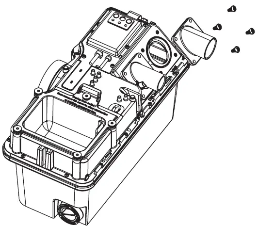
Discharge and Vent FlangesBoth the discharge and vent flanges are fastened to the main cover and can be removed by unscrewing the four fasteners and pulling the flange away from the main cover.
Toilet Sealing RingThe seal between the toilet and the macerator consists of a rubber ring connected to the macerator into which the toilet slides. The rubber ring stretches and forms a seal around the discharge hub of the toilet. This rubber ring is replaceable by unclipping the plastic retainer and then pulling the ring outward. Installation is reversed, first slide the rubber ring onto the macerator, followed by the retaining ring.

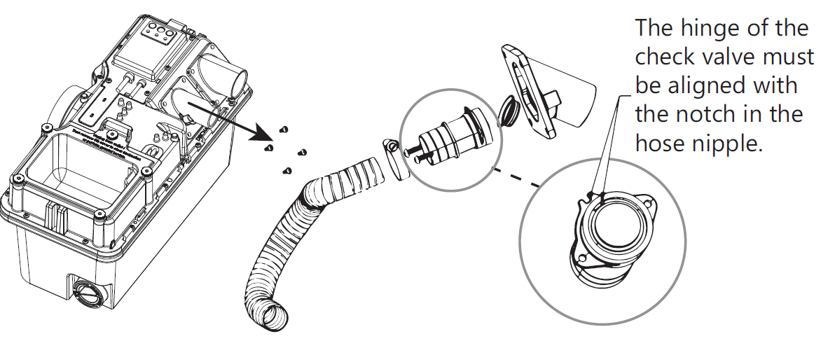
Check ValveThe discharge flange has an integrated check valve. The valve is held in place by a support backing plate that is also connected to the discharge hose. To access the check valve, first remove the discharge flange from the main cover by removing 4 screws. Then remove the hose, followed by the two screws. The hose nipple can then be separated from the flange by pulling it outward. The check valve snaps onto the hose nipple.When reinstalling, the hinge of the check valve must be aligned with the “notch” in the hose nipple or backing plate. After installation of the hose nipple, confirm the check valve opens completely.
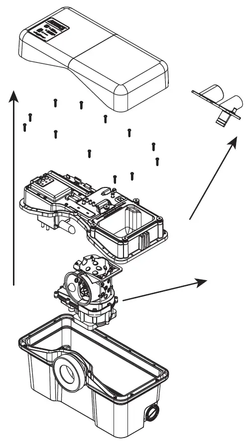
Access CoverThe access cover is secured to the main cover with five fasteners. If required, use the 3/16” Allen wrench supplied to loosen the fasteners. Once the screws have been removed, the access cover can be lifted upward. Some manipulation might be necessary if the macerator is located directly under the toilet reservoir tank.

Once the access cover is removed, the power cartridge can be slid toward the opening by grasping the handle of the basket and pulling to the right toward the opening. In some instances, debris might be caught between the tank and the basket so somemanipulation might be required.With the power cartridge fully slid over, the cutters should be in view at the center of the basket. Any obstruction or object can be removed at this point. The cutters are very sharp and extreme caution should be used.
Interconnect HoseA hose connects the discharge of the motor cartridge (pump) to the discharge flange. To remove this hose, follow the procedure Discharge and Vent Flanges and Accessibility to Motorized Cartridge. Both ends of the hose are secured with clamps.
Cutter Blade Replacement
The cutter blades are designed and rigorously tested to last indefinitely without need for service or replacement in ordinary applications. In the unlikely event that the cutter blades need replacement, Liberty Pumps recommends replacement kit # K001370 (440A Stainless Steel Cutter Blades hardened to Rockwell 54c) available from http://www.libertypumps.com/Services/Replacement-Parts or equivalent substitute.To replace the cutter blades, the 3/16” Allen wrench (supplied) should be inserted into one of the holes located on the basket floor. This will create a wedge preventing the cutter blade assembly from turning. The locking fastener can be unscrewed with the use of a 7/16” socket (1/4” drive). Once loose, the screw and cap can be removed by pulling upward, exposing the two cutter blades. Carefully insert the new cutter blade onto the two pins. Replace the cap and screw.The base of the cutting cartridge can be replaced as well. After removing the cutter blades, a thin slotted screwdriver can be inserted into the center hole and, once engaged, the base can be rotated counterclockwise until it is free.

Accessibility to Motorized Cartridge
The motorized cartridge can be accessed through the access opening or removal of the main cover.
Removal of Power Cartridge Through the Access Opening:Once the access cover has been removed and the basket is slid toward the opening, the four fasteners securing the basket can be unscrewed. The basket can then be removed through the opening followed by the power cartridge.
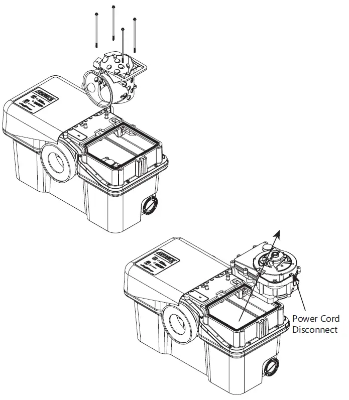
Removal of Power Cartridge by Disassembly of Macerator:If a full port ball valve was installed in the discharge line, it should be closed to eliminate the possibility of waste discharging from the discharge pipe. Next, the discharge and vent flanges should be separated from the main cover by removing 4 screws from each.The main cover can then be detached from the tank by removing the fasteners on the periphery of the tank. The main cover can then be lifted upward exposing the power cartridge.
Power Cord: The inner connecting power cord running from the switch box to the motorized cartridge can be detached by unscrewing the compression nut located at the motorized cartridge.
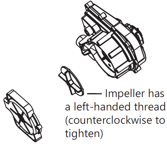
Impeller AccessOnce the bottom of the motorized cartridge is accessible, the fasteners retaining the volute can be removed and the volute separated by pulling it away. The impeller chamber can now be cleaned if required, or the impeller can be replaced.Note: the impeller has a left-handed thread. To remove, use a slotted screwdriver to hold the shaft and turn the impeller clockwise.
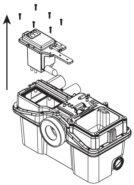
Control SwitchThe control switch cartridge is mounted to the main cover with fasteners. The control has two power cords; first is the main power cord that plugs into the GFCI receptacle and the other powers the motorized cartridge. The motorized cartridge must be removed to disconnect this cord. Refer to Accessibility to Motorized Cartridge for details.
Troubleshooting
Liberty Pumps, Inc. assumes no responsibility for damage or injury due to disassembly in the field. Disassembly, other than at Liberty Pumps or its authorized service centers, automatically voids warranty.In addition to the Alarm Panel Help in Table 1 and the Troubleshooting Matrix in Table 2, verify the following:
Plumbing SystemFlush toilet and ensure water supply is turned on.Electrical SystemEnsure breaker and receptacle GFCI are on. Check condition of circuit breaker or fuse. Ensure plug is not loose. If the pumping unit thermal overload has activated, it will take about 20 minutes to reset.Decorative CoversEnsure decorative covers are installed and fully seated such that safety switch is activated. The green LED is solid when safety switch is properly activated.Hydraulic SystemCheck that the discharge pipe and vent pipe are not blocked.Water LeakageIf the macerating pump turns on intermittently without flushing the toilet or collecting water drainage from sink, shower, or tub, check for leakage from the toilet tank flush valve.
Table 1. Alarm Panel Help
| Label
LED Color/State |
Condition | Corrective Action |
| ALARM
Red/Blinking |
Water is not being evacuated from holding tank. | 1. Verify unit is plugged into outlet.
2. Verify Green LED is steady, indicating normal operating condition. 3. Check discharge line for blockage. 4. If items 1-3 do not remedy the alarm condition, refer to Table 2 Troubleshooting Matrix. |
| LOW BATTERY
Yellow/Steady |
Battery is missing, defective, or needs to be replaced. | 1. Replace with new battery. |
| POWER
Green/Steady |
Normal operating condition. | |
| POWER
Green/Blinking |
Safety switch condition (no signal from safety switch; unit will not operate). | 1. Verify decorative covers in place.
2. Verify magnet in place on underside of decorative cover. 3. Safety switch is broken; consult factory. |
WARNING: RISK OF ELECTRIC SHOCK
- Accidental contact with electrically live parts, items, fluid, or water can cause serious injury or death.
- Always disconnect pump (macerator) from power source before handling or making any adjustments. Fatal electrical shock could occur.
Table 2. Troubleshooting Matrix
| Problem | Possible Cause | Corrective Action |
| Water is entering the macerator holding tank slowly | ||
| Toilet flushes normally but evacuates or drains from the bowl slowly.
• Macerator sounds normal and runs for 4 seconds, then after some time runs for 4 seconds. • No alarm. |
The toilet or discharge extension might be blocked. | The piping must be cleaned. |
| Poor vent. | Unit must be vented properly to open air to allow water to enter the macerator tank. Confirm vent is clear.
Do not use a quick vent. |
|
| Accumulation in the strainer basket. | Repetitively flush clean water and allow the macerator to clear debris. If unit is unable to self-clear the blockage, the access cover should be removed for manual cleaning. See Access Cover on page 10. | |
| Water is unable to enter the macerator holding tank | ||
| Toilet flushes normally but does not evacuate or drain from the bowl.
• Macerator sounds normal and runs for 4 seconds then remains off. • No alarm. |
The toilet discharge or extension pipe may be blocked. | The piping must be cleaned. |
| Unit not vented correctly. | Unit must be vented properly to open air to allow water to enter the macerator tank. Confirm vent is clear.
Do not use a quick vent. |
|
| The macerator is jammed | ||
| Toilet Flushes normally but macerator does not turn on or just hums.
• Green LED is on steady. |
The cutter or impeller are jammed preventing the motor from turning. | Clear the cutter or impeller of blockage. |
| Internal motor problem. | The pump cartridge must be replaced. | |
| The macerator is unable to evacuate its holding tank and is cycling on thermal overload | ||
| Toilet flushes normally but does not evacuate or drain from the bowl.
• Macerator starts to run and sounds normal (running) then stops after 5-10 min. Restarts after 30 to 60 min. • Alarm is activated. |
Damaged impeller. | Replace impeller. See Impeller Access on page 12. |
| Check valve stuck closed. | Confirm the check valve is functioning properly; if not, repair or replace. See Check Valve on | |
| Internal hose damaged or disconnected. | Confirm the internal hose is functioning properly; if not, replace. See Control Switch on page 12. | |
| If the macerator was installed with a ball valve in the discharge line, valve may be closed. | Open ball valve. | |
| Air lock. | The volute has a passageway to allow trapped air to escape. This passageway must be cleaned of obstruction. See Accessibility to Motorized Cartridge on page 11. | |
| Volute inlet plugged. | Clean volute inlet, located on the bottom of the pump cartridge. See Accessibility to Motorized Cartridge on page 11. |
| Problem | Possible Cause | Corrective Action |
| The macerator has electrical power, safety switch is off | ||
| The macerator does not start up (the macerator has electrical power, safety switch is off).
• Green LED is blinking. |
Decorative cover not installed. | Both halves of the decorative cover must be installed and fitted properly on the unit. See Check Valve on page 10. |
| The right decorative cover (over the access cover) should have a magnet located on a post. This magnet activates a safety switch. | Replace magnet or entire right decorative cover. See Check Valve on page 10. | |
| The toilet has an inadequate flush volume, possible blockage of the strainer basket, or improper venting | ||
| Waste build up in the toilet bowl. | Inadequate water level in the reservoir tank. | Check and/or adjust the water fill mechanism so that the water level matches the reference line in the tank. |
| Strainer basket requires cleaning. | Clear debris from the strainer basket. See Accessibility to Motorized Cartridge on page 11. | |
| Unit not vented correctly. | Unit must be vented properly to open air to allow water to enter the macerator tank. Confirm vent is clear.
Do not use a quick vent. |
|
| No electrical power or battery protection mode | ||
| The macerator has no LEDs illuminated when power is connected (no electrical power or battery protection mode).
• All LEDs are off. |
The macerator is either not plugged in, supply breaker is turned off, or GFCI receptacle has tripped. | Check electrical power source. |
| Control system in battery protection mode. | 1. Unplug macerator from receptacle.
2. Remove the 9V battery that powers the alarm. 3. Plug the macerator back into the receptacle. 4. Re-install the 9V battery. |
|
| No electrical power | ||
| The macerator does not start up.
• Green LED is off. |
The macerator is either not plugged in, supply breaker is turned off, or GFCI receptacle has tripped. | Check electrical power source. |
| Solid debris in basket | ||
| During a pumping cycle, a rattling noise is emanating from the macerator. | Solid object larger than 1/2” is trapped in the cutting basket of the macerator. | The access cover should be removed for manual cleaning. See Access Cover on page 10. |
| Pump is unable to evacuate tank | ||
| Alarm sounds frequently (pump unable to evacuate tank). | Damaged impeller. | Replace impeller. See Impeller Access on page 12. |
| Volute inlet clogged. | Clean volute inlet. See Accessibility to Motorized Cartridge on page 11. | |
| Internal hose damaged. | Confirm the internal hose is functioning properly; if not, replace. See Control Switch on page 12. | |
| Air lock. | The volute has a passageway to allow trapped air to escape. This passageway must be cleaned of obstruction. See Accessibility to Motorized Cartridge on page 11. | |
| Application. | The pumping capacity has been exceeded by the rate of incoming water. Either reduce flow coming into the macerator or reduce the pumping head. |
| Problem | Possible Cause | Corrective Action |
| General plumbing | ||
| The macerator pulses for no apparent reason. | Water leakage from the toilet reservoir. | Check flush valve and related components in the reservoir tank. |
| Check valve failure of the macerator. | The discharge flange contains a check valve that requires cleaning or replacement. See Check Valve on page 10. | |
| General plumbing | ||
| Water backs up into shower tray.
• Alarm is not activated. |
Blockage or inadequate slope of pipe. | Clear blockage in piping, or increase pitch of discharge pipe. Typically ¼” drop per foot is adequate for a gravity drain. |
| The inlet flappers of the macerator are not functioning. | Clear any buildup in the macerator holding tank that is preventing the flappers from opening. See Accessibility to Motorized Cartridge on page 11. | |
| General plumbing | ||
| Macerator is noisy when running. | Rattling piping. | Both the discharge and vent plumbing should be secured using appropriate pipe clamping. |
| Foreign object in cutter basket. | The access cover should be removed for manual cleaning. See Access Cover on page 10. | |
| General plumbing | ||
| During the draining of the bathtub, the alarm sounds and/or water backs up into the toilet. | The inflow is greater than the macerator can handle. | A full port ball valve should be installed between the tub and macerator. Throttle down or partially close the ball valve until the macerator can handle the drainage rate from the tub. |
| System is backing up | ||
| Water backs up into shower tray.
• Alarm is activated. |
Damaged impeller. | Replace impeller. See Impeller Access on page 12. |
| Volute inlet clogged. | Clean volute inlet. See Accessibility to Motorized Cartridge on page 11. | |
| Internal hose damaged. | Confirm the internal hose is functioning properly; if not, replace. See Control Switch on page 12. | |
| Air lock. | The volute has a passageway to allow trapped air to escape, this passageway must be cleaned of obstruction. See Accessibility to Motorized Cartridge on page 11. | |
| Incoming flow rate is greater than pump capacity. | The unit is capable of handling up to two shower heads—multiple (3 and up) shower heads must be avoided. | |
| Check valve failure of the macerator. | The discharge flange contains a check valve that either requires cleaning or replacement. See Check Valve on page 10. |
Warranty
Liberty Pumps Wholesale Products Limited WarrantyLiberty Pumps, Inc. warrants that Liberty Pumps wholesale products are free from all factory defects in material and workmanship for a period of three (3) years from the date of purchase (excluding batteries). The date of purchase shall be determined by a dated sales receipt noting the model and serial number of the pump. The dated sales receipt must accompany the returned pump if the date of return is more than three years from the date of manufacture noted on the pump nameplate.The manufacturer’s sole obligation under this Warranty shall be limited to the repair or replacement of any parts found by the manufacturer to be defective, provided the part or assembly is returned freight prepaid to the manufacturer or its authorized service center, and provided that none of the following warranty-voiding characteristics are evident:The manufacturer shall not be liable under this Warranty if the product has not been properly installed, operated, or maintained per manufacturer instructions; if it has been disassembled, modified, abused, or tampered with; if the electrical cord has been cut, damaged, or spliced; if the pump discharge has been reduced in size; if the pump has been used in water temperatures above the advertised rating; if the pump has been used in water containing sand, lime, cement, gravel, or other abrasives; if the product has been used to pump chemicals, grease, or hydrocarbons; if a non-submersible motor has been subjected to moisture; or if the label bearing the model and serial number has been removed.Liberty Pumps, Inc. shall not be liable for any loss, damage, or expenses resulting from installation or use of its products, or for indirect, incidental, and consequential damages, including costs of removal, reinstallation or transportation.There is no other express warranty. All implied warranties, including those of merchantability and fitness for a particular purpose, are limited to three years from the date of purchase. This Warranty contains the exclusive remedy of the purchaser, and, where permitted, liability for consequential or incidental damages under any and all warranties are excluded.
7000 Apple Tree AvenueBergen, NY 14416ph: 800-543-2550fax: 585-494-1839www.LibertyPumps.com
 report this ad
![]()
References
[xyz-ips snippet=”download-snippet”]