Liberty Pumps Pro370-Series Simplex Sewage/Grinder
 Systems Installation Guide

* with optional Access Riser7000 Apple Tree Avenue Bergen, NY 14416ph.: 800-543-2550fax: 585-494-1839www.LibertyPumps.com
Safety Guidelines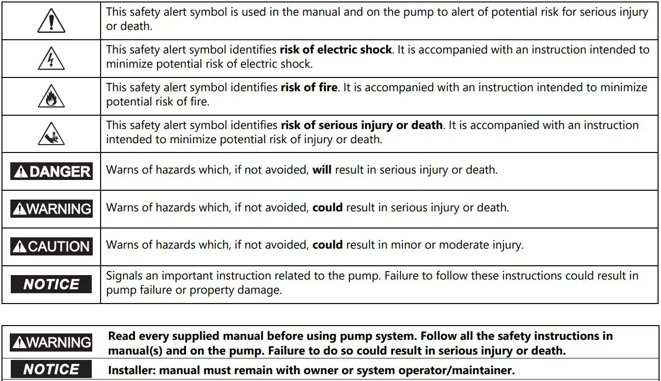 Record information from pump nameplate:
Keep this manual handy for future reference.For replacement manual, visit LibertyPumps.com, or contact Liberty Pumps at 800-543-2550.Retain dated sales receipt for warranty.
Pump Model #:_______________________________Pump Serial #:_______________________________System #:_______________________________Manufacture Date:_______________________________Install Date:_______________________________
Safety Precautions
![]() WARNING
WARNING ![]() RISK OF ELECTRIC SHOCK
RISK OF ELECTRIC SHOCK
- Accidental contact with electrically live parts, items, fluid, or water can cause serious injury or death.
- Always disconnect pump(s) from power source(s) before handling or making any adjustments to either the pump(s), the pump system, or the control panel.
- All installation and maintenance of pumps, controls, protection devices, and general wiring shall be done by qualified personnel.
- All electrical and safety practices shall be in accordance with the National Electrical Code®, the Occupational Safety and Health Administration, or applicable local codes and ordinances.
- Do not remove cord and strain relief, and do not connect conduit to pump.
- Pump shall be properly grounded using its supplied grounding conductor. Do not bypass grounding wires or remove ground prong from attachment plugs. Failure to properly ground the pump system can cause all metal portions of the pump and its surroundings to become energized.
- Do not handle or unplug the pump with wet hands, when standing on damp surface, or in water unless wearing Personal Protective Equipment.
- Always wear dielectric rubber boots and other applicable Personal Protective Equipment (PPE) when water is on the floor and an energized pump system must be serviced, as submerged electrical connections can energize the water. Do not enter the water if the water level is higher than the PPE protection or if the PPE is not watertight.
- Do not lift or carry a pump or a float assembly by its power cord. This will damage the power cord, and could expose the electrically live wires inside the power cord.
- The electrical power supply shall be located within the length limitations of the pump power cord, and for below grade installations it shall be at least 4 ft. (1.22 m) above floor level.
- Do not use this product in applications where human contact with the pumped fluid is common (such as swimming pools, fountains, marine areas, etc.).
- Protect the power and control cords from the environment. Unprotected power and control (switch) cords can allow water to wick through ends into pump or switch housings, causing surroundings to become energized.
- Single-phase 208/230V pumps shall only be operated without the float switch by using the circuit breaker or panel disconnect.
- Some products may have internal capacitors that could cause shock. Avoid contact with plug ends after removing from energy source.
![]() WARNING
WARNING ![]() RISK OF FIRE
RISK OF FIRE
- Do not use an extension cord to power the product. Extension cords can overload both the product and extension cord supply wires. Overloaded wires will get very hot and can catch on fire.
- This product requires a separate, properly fused and grounded branch circuit, sized for the voltage and amperage requirements of the pump, as noted on the nameplate. Overloaded branch circuit wires will get very hot and can catch on fire. When used, electrical outlets shall be simplex of the appropriate rating.
- Do not use this product with or near flammable or explosive fluids such as gasoline, fuel oil, kerosene, etc. If rotating elements inside pump strike any foreign object, sparks may occur. Sparks could ignite flammable liquids.
- These pumps are not to be installed in locations classified as hazardous in accordance with the National Electric Code®, ANSI/NFPA 70.
- Sewage and effluent systems produce and may contain flammable and explosive gases. Prevent introduction of foreign objects into basin as sparks could ignite these gases. Exercise caution using tools and do not use electronic devices or have live, exposed electrical circuits in or around basins, open covers and vents.
![]() WARNING
WARNING ![]() RISK OF SERIOUS INJURY OR DEATH
RISK OF SERIOUS INJURY OR DEATH
- Do not modify the pump/pump system in any way. Modifications may affect seals, change the electrical loading of the pump, or damage the pump and its components.
- All pump/pump system installations shall be in compliance with all applicable Federal, State, and Local codes and ordinances.
- Do not allow children to play with the pump system.
- Do not allow any person who is unqualified to have contact with this pump system. Any person who is unaware of the dangers of this pump system, or has not read this manual, can easily be injured by the pump system.
- In 208/230V installations, one side of the line going to the pump is always “hot”, whether the float switch is on or off. To avoid hazards, install a double pole disconnect near the pump installation.
- Vent basin in accordance with local code. Proper venting of sewer and effluent gases alleviates poisonous gas buildup and reduces the risk of explosion and fire from these flammable gases.
- Wear adequate Personal Protective Equipment when working on pumps or piping that have been exposed to wastewater. Sump and sewage pumps often handle materials that can transmit illness or disease upon contact with skin and other tissues.
- Do not enter a pump basin after it has been used. Sewage and effluent can emit several gases that are poisonous.
- Do not remove any tags or labels from the pump or its cord.
- Keep clear of suction and discharge openings. To prevent injury, never insert fingers into pump while it is connected to a power source.
- Do not use this product with flammable, explosive, or corrosive fluids. Do not use in a flammable and/or explosive atmosphere as serious injury or death could result.
- This product contains chemicals known to the State of California to cause cancer and birth defects or other reproductive harm. www.p65warnings.ca.gov.
- A grinder pump contains metal parts that rotate at high speeds. Be careful around pump base while power is connected. Make sure that the pump is either in the tank or clear from people and wires when in operation.
NOTICE
- Do not use pumps with fluid over 140°F (60°C). Operating the pump in fluid above this temperature can overheat the pump, resulting in pump failure.
- Do not use pump system with mud, sand, cement, hydrocarbons, grease, or chemicals. Pump and system components can be damaged from these items causing product malfunction or failure. Additionally, flooding can occur if these items jam the impeller or piping.
- Do not introduce any consumer item that is not toilet paper into a non-grinder (dewatering, effluent, sewage) pump/pump system. This includes, but is not limited to the following: feminine products, wipes, towels, towelettes, dental floss, swabs, pads, etc. Items such as these put the pump under undo strain and can result in pump/pump system failure. Additionally, it creates conditions for discharge line blockage.
- Do not run dry.
- The Uniform Plumbing Code® states that sewage systems shall have an audio and visual alarm that signals a malfunction of the system, to reduce the potential for property damage.
- Do not exert heavy pressure or run heavy equipment on the backfill material as this could cause the tank to collapse.
- Do not position the pump float directly under the inlet from drain tile or in the direct path of any incoming water.
- 700-Series are not suitable for outdoor applications.
- Pro370 and vertical discharge Pro380 and ProVore 380-Series systems require an Access Riser for outdoor use. Consult Liberty Pumps for ordering information.
- Unless specifically noted, covers are not traffic rated.
Introduction
Before installation, read the following instructions carefully. Each pump is individually factory tested to ensure proper performance. Closely following these instructions will eliminate potential operating problems, assuring years of trouble-free service.
ProVore grinder systems (including ProVore700-Series) easily handle solids and sewage waste found in typical residential applications. Their unique cutter system grinds difficult wastes and then pumps it through a 1-1/2″ or 2″ discharge line. The ProVore-Series system is supplied with a 2″ discharge outlet. Do not increase this pipe size above 2″ as adequate flow rates may not be achieved for proper operation. Discharge sizes may be reduced to 1-1/4″. Consult Liberty Pumps for proper pipe and system sizing.
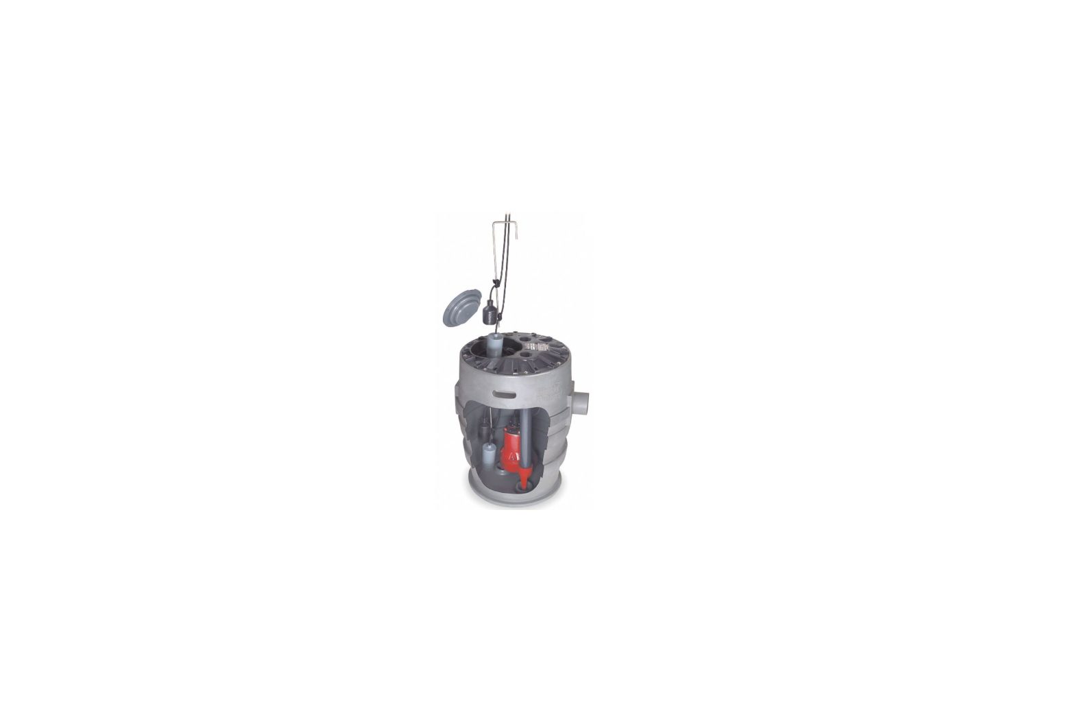
Pro-Series and ProVore-Series vertical discharge systems come with an integral control system with alarm and QuickTree® float system. Pump and alarm floats are pre-set on the QuickTree system at proper operating levels. The QuickTree system is located under a separate access cover for ease of maintenance and service. Floats for both pump activation and alarm are mounted on a stainless steel tree (rod), separate from the pump. There is no need to disconnect plumbing or remove the pump to inspect service or replace floats. QuickTree floats are preset at the factory for optimum operating levels and should not be adjusted.
Systems also feature a clear disposable construction cover designed to protect the system during rough-in and masonry work. The protective cover should remain in place until finish plumbing; however, it can be removed and reinstalled if required. The cover is snapped into the threaded ports of the discharge and vent. To remove the clear cover, simply pull upward, disengaging it from the discharge and vent holes.
Pro-Series and ProVore-Series side discharge systems feature a 2″ side discharge and 4″ no-hub type inlet. Systems come pre-assembled from the factory with an automatic pump.
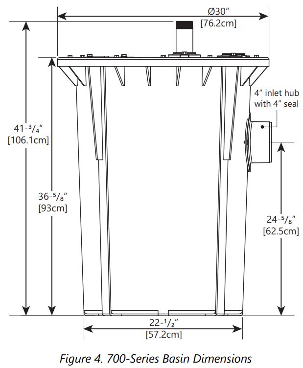
700-Series systems (non-grinder types) feature a heavy-duty basin with 4″ inlet hub pre-assembled to basin. Systems come pre-assembled from the factory with pump and automatic controls pre-mounted, requiring no system assembly at job site. The cover is equipped with a 2″ or 3″ discharge and 2″ or 3″ vent flange.
Was current system sized by a professional? Minimum fluid flows are required in sewage applications. Consult Liberty Pumps for proper pump sizing prior to installation.
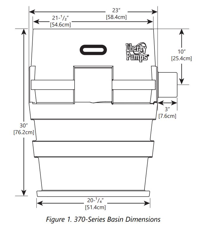
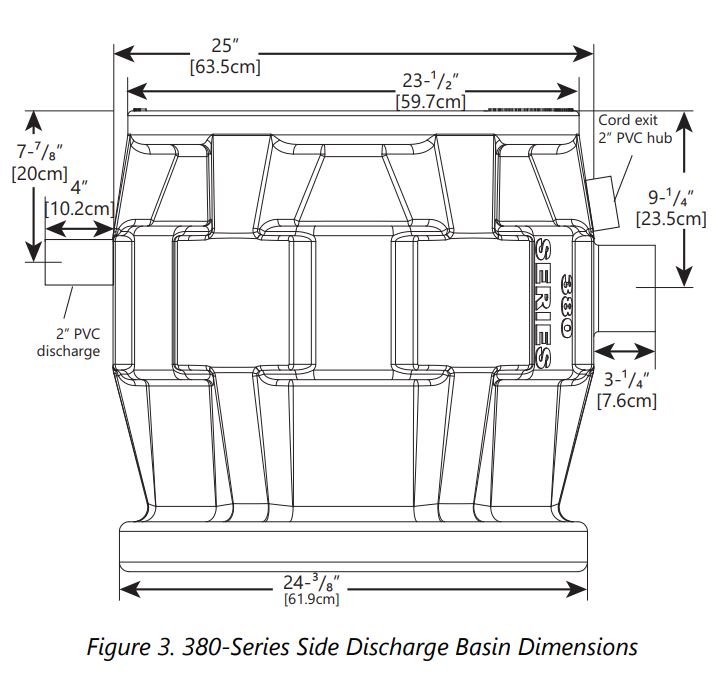
Basin Dimensions

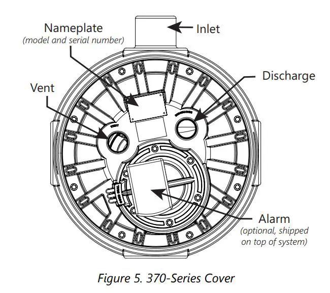
Cover Descriptions


In-Ground Basin Installation
- 700-Series are not suitable for outdoor applications.
- Pro370 and vertical discharge systems Pro380 and ProVore 380-Series systems require an Access Riser for outdoor use. Consult Liberty Pumps for ordering information.
- Unless specifically noted, covers are not traffic rated.
ProVore and Pro-Series basins can be installed in both indoor and outdoor applications. The 700-Series basins are not suitable for outdoor applications and can only be installed indoors.
ExcavationExcavate the hole as small as possible, with a minimum recommended 8″ diametrical clearance around the tank. Never place the basin directly in contact with rocks or other sharp objects. Place only fine, 1/8″ to 3/4″ pea gravel or 1/8″ to 1/2″ washed, crushed stone as bedding between the basin and the hole walls. Do not use sand or native soil as backfill. Properly compact underneath the basin to provide a solid, level base that can support the weight of the filled basin. It is recommended that the top lip of the basin be level with the finished floor.
Initial BackfillOnly fine, 1/8″ to 3/4″ pea gravel or 1/8″ to 1/2″ washed, crushed stone should be used around the bottom of the basin to hold it in place. Do not use sand or native soil as backfill. Make the inlet connection as required for particular basin.
Inlet ConnectionPro-Series basins have a 4″ inlet molded to the side of the tank. This inlet is sized to accept a 4″ no-hub type coupling. 700-Series basins use a hub with a 4″ seal for inlet connection. Connect the gravity drainage line from the fixtures to this hub.
Final BackfillLarge rocks, clods, and foreign objects should be kept out of the backfill material. Only fine, 1/4″ to 3/4″ pea gravel, or 1/8″ to 1/2″ washed, crushed stone is recommended. Do not use sand or native soil as backfill. Mound the backfill slightly and allow for natural settling. Provide access to the basin cover for maintenance and service.
NOTICE
- Do not exert heavy pressure or run heavy equipment on the backfill material as this could cause the tank to collapse.
Installation
![]() WARNING
WARNING ![]() RISK OF ELECTRIC SHOCK
RISK OF ELECTRIC SHOCK
- All installation and maintenance of pumps, controls, protection devices, and general wiring shall be done by qualified personnel.
- All electrical and safety practices shall be in accordance with the National Electrical Code®, the Occupational Safety and Health Administration, or applicable local codes and ordinances.
NOTICE
- 700-Series are not suitable for outdoor applications.
- Pro370 and vertical discharge systems Pro380 and ProVore 380-Series systems require an Access Riser for outdoor use. Consult Liberty Pumps for ordering information.
- Unless specifically noted, covers are not traffic rated.
- Do not increase 702/PRG system discharge pipe size above 2″ as adequate flow rates may not be achieved for proper operation. Contact Liberty Pumps with questions regarding proper pipe sizes and flow rates.
Electrical ConnectionsWith main power disconnected, complete pump and control wiring connections per manufacturer’s wiring diagrams included with the control panel as applicable. All wires should be checked for unintentional grounds after the connections are made.
Discharge
- ProVore grinder systems including ProVore700-Series: discharge size can be reduced to 1-1/4″.
- Pro-Series, ProVore-Series and 700-Series non-grinder systems: discharge size must not be smaller than 2″.
Using an adapter, connect the discharge pipe to the threaded 2″ or 3″ port provided on the cover (or the 2″ PVC nipple used on side discharge models).In some applications, it may be necessary to increase the pipe size to reduce friction losses. Contact Liberty Pumps with questions regarding proper pipe sizes and flow rates.
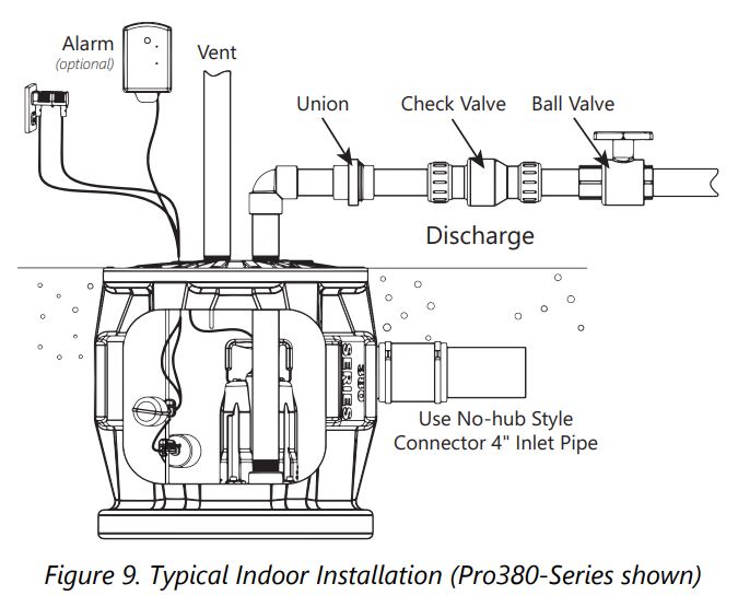
Install the remaining discharge line. In vertical discharge applications, a union should be installed just above the cover to facilitate pump removal if necessary (side discharge applications are equipped with an in-basin union).
For both vertical and side discharge systems, a check valve is required after the union to prevent the backflow of liquid after each pumping cycle. A gate or ball valve should follow the check valve to allow periodic cleaning of the check valve or removal of the pump. The remainder of the discharge line should be as short as possible with a minimum number of turns, to minimize friction head loss. Larger pipe sizes may be required to eliminate friction head loss over long runs. Contact Liberty Pumps or other qualified person if there are questions regarding proper pipe size and flow rates.
Figure 9 shows a typical installation. Variations may apply to actual installation.
VentFor both side and vertical discharge systems, the vent size must be in accordance with applicable codes, but not less than the discharge size.
On vertical discharge models, a threaded 2″ or 3″ connection is provided on top of the cover. The vent must be piped to the existing building vent, or extended outside on its own standpipe.
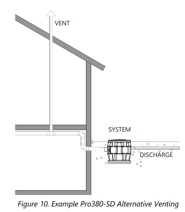
On side discharge models, venting is accomplished through the inlet. See Figure 10 for Pro380-SD venting example through the inlet pipe as an alternative solution.
Pro-Series systems shipped with steel pipe option have a rubber grommet seal on the discharge instead of female NPT connections.
Piggyback Switch Operation
![]() WARNING
WARNING ![]() RISK OF ELECTRIC SHOCKSingle-phase 208/230V pumps shall only be operated without the float switch by using the circuit breaker or panel disconnect. Some products may have internal capacitors that could cause shock. Avoid contact with plug ends after removing from energy source.
RISK OF ELECTRIC SHOCKSingle-phase 208/230V pumps shall only be operated without the float switch by using the circuit breaker or panel disconnect. Some products may have internal capacitors that could cause shock. Avoid contact with plug ends after removing from energy source.
All Pro370 and vertical discharge Pro380-Series models come factory-equipped with the float switch mounted on the QuickTree assembly. These models come with two cords–one to the float switch and the other to the pump motor. The switch cord has a series (piggyback) plug enabling the pump (motor) cord to be plugged into the back of it (Figure 11). The purpose of this design is to allow manual operation of the pump.
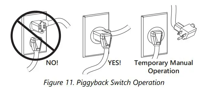
For automatic operation, the two cords should be interconnected and plugged into a separately fused, grounded outlet of proper amp capacity for the selected pump model. Both cords are equipped with 3-prong plugs and must be plugged into a properly grounded 3-wire receptacle. Do not remove the ground prongs.
For manual operation, or in the event of switch failure, the pump cord can be separated and plugged into the electrical outlet directly, bypassing the switch and using the circuit breaker or panel disconnect to operate the pump.
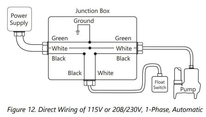
Automatic Pump Direct Wiring
![]() WARNING
WARNING ![]() RISK OF SERIOUS INJURY OR DEATH
RISK OF SERIOUS INJURY OR DEATH
- In 208/230V installations, one side of the line going to the pump is always “hot”, whether the float switch is on or off. To avoid hazards, install a double pole disconnect near the pump installation.
If a 1-phase pump will be wired directly into a junction box, and it is necessary to remove the plug, a certified electrician shall complete the wiring in accordance with the National Electric Code and applicable local codes. A disconnecting means for the pump shall be located in sight from the pump/basin location. See Figure 12 for direct wire installation of 1-phase, automatic pumps.
Access Cover and Float Switch Control
370/380-Series Vertical DischargeLiberty Pumps Pro370 systems and vertical discharge 380-Series systems feature QuickTree technology. Floats for both pump activation and alarm (if equipped) are mounted on the QuickTree, separate from the pump.The QuickTree float system uses a stainless steel mounting rod (tree) and specially designed cord clamping brackets to affix the pump float and (optional) alarm float in the system. All floats are preset at the factory at optimum operating levels and should not be adjusted. Field adjusting floats may cause improper activation or turn-off of the pump and optional alarm.
QuickTree removal and float inspection: The QuickTree system is located under the separate access cover to help ease inspection, service, and replacement of a float. To inspect the float(s), simply unbolt the access cover and lift out the QuickTree assembly from its holder. There is no need to disconnect plumbing or remove the pump. Vertical discharge systems feature a manual pump (with no switch attached directly to the pump). Operation of the pump is accomplished by the QuickTree system.
Re-inserting the QuickTree: After service or inspection of the floats, re-insert the QuickTree into its holder. It is important that cords from the pump motor, float switch, and optional alarm float are properly sealed in the specially designed rubber sealing channels under the access cover. Proper sealing is required to keep sewer gas from leaking from the system. Place the cords securely in the rubber channels as shown in Figure 13 [left], being careful to remove excessive cord “slack” from inside the system.
IMPORTANT: Three cord channels are provided. For systems without the alarm option, only two channels are used and the third must be “plugged” with an attached rubber plug seal. See Figure 13 [right]. If the alarm cord is present, all three channels will be used. All rubber cover gaskets are permanently attached and do not require replacement.RUBBER PLUG SEAL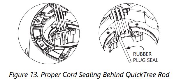
QuickTree Settings
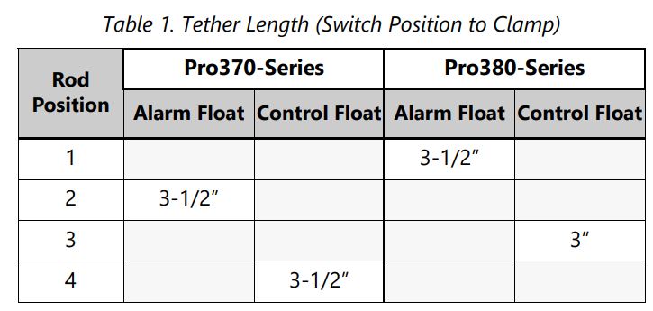
When servicing the QuickTree, place the switch cord into the trough or channel and then slip the stainless steel rod through the clamp. Tighten the screw with a Phillips screwdriver, being careful not to overtighten. Flats have been stamped on the rod to designate float position, and the screw should be tightened onto the flat. Tether length is the amount of cord between the clamp and float.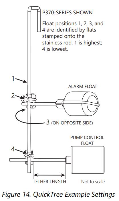
380-Series Side DischargeThe 380-Series Side Discharge cover provides access to the float and alarm cord entry/exit seals. QuickTree is not available on 380-Series Side Discharge systems. Refer to Figure 7. Side discharge 380-Series systems are equipped with an automatic pump that has the control float attached to the pump while the alarm float (if equipped) is on the discharge pipe.
700-SeriesThe 700-Series cover contains access to the float and alarm cord entry/exit seals. QuickTree is not available on 700-Series systems. Refer to Figure 8. 700-Series systems are equipped with an automatic pump that has the control float attached to the pump while the alarm float (if equipped) is on the discharge pipe.
Supplemental Installation Instructions
Pro370XL/Pro380XL-Series 10′ Stack Test BasinsXL-Series sewage ejector basins are designed to withstand the 10′ stack test required by some municipalities. Proper installation of the specified cover flange is essential to ensure that the test is met. Strict adherence to these instructions is required. Under no circumstances should the cover be installed in a manner inconsistent with these instructions.
Types of SystemsXL-Series basins are available as fully assembled systems complete with pump and discharge piping, as basin and cover assembly kits with no pump or plumbing, and as basins only. Follow the instructions below, as applicable, to correspond to the specific type of system.
Basin InstallationFor all systems, refer to the primary instructions supplied with this ejector system or basin for excavating the pit, plumbing connections, and backfilling. If the top of the basin is below grade, an Access Riser (model ARC18) is required. The maximum burial depth is 18″ with respect to the top of the basin. 370-Series and top discharge 380-Series systems require an Access Riser for outdoor use. Consult Liberty Pumps at 1-800-543-2550 or a local distributor for more information on ARC Series Access Risers.
Installing the Pump in XL-Series Basin or XL Basin and Cover Assembly Kit
- Liberty Pumps XL-Series basins, purchased separately, will require the appropriate 16-bolt Pro-Series cover assembly to make an effectively sealed ejector system. Contact Liberty Pumps customer service for the proper cover for the application.
- Size the length of the discharge piping to reach from the discharge of the pump to be within the discharge pipe socket with integral lip seal on the underside of the Pro-Series cover. Liberty Pumps sewage pumps will use threaded-one-end (TOE) nipples of 23.75″ length for Pro370XL-Series Basins, or 17.50″ long for Pro380XL-Series Basins. Install the pipe into the threaded discharge of the pump.
- Lower the pump into the basin, fitting the pump legs into the torque stops.
- Insert power cord for the pump–and the piggyback switch cord, if so equipped–through the underside of the inspection cover hole and position cover over pipe nipple while aligning the bolt holes. Sealant (such as silicone) can be applied on both sides of the rubber gasket surface to ensure proper sealing. Use sixteen 1/4-20 UNC bolts and washers to secure cover to the basin. Tighten bolts to 40 inch-pounds. Do not overtighten bolts. The soft, integral gasket will conform to the top of the tank. The bolts may be re-torqued up to 60 inch-pounds to seal any leaks that may occur during a 10′ stack test.
- Liberty Pumps recommends the use of manual type pumps and the appropriate Liberty Pumps QuickTree Switch Kit for mounting of pump control and alarm floats. Contact customer service for ordering information. Install the QuickTree Kit per instructions included. Liberty Pumps automatic type pumps with piggyback float switches may also be used. Lay the power cable and switch cable in the grooves in the inspection cover recess as shown in the primary instructions included with this system. Attach the inspection cover to the main cover using supplied bolts and washers. Sealant (such as silicone) can be applied on both sides of the rubber gasket surface to ensure proper sealing. Tighten the bolts furthest away from the power cord grooves first, torqueing to 40 inch-pounds. Do not overtighten bolts. The soft, integral gasket will conform to the top of the cover and power cords. The bolts may be re-torqued up to 60 inch-pounds to seal any leaks that may occur during a 10′ stack test.
![]() Pro370XL and Pro380XL Series Basins IAPMO listed, # 4361
Pro370XL and Pro380XL Series Basins IAPMO listed, # 4361
Operation
Refer to the Startup and Operation sections provided in the supplied pump, control panel, alarm manuals as applicable.
Maintenance and Troubleshooting
![]() WARNING
WARNING ![]() RISK OF ELECTRIC SHOCK
RISK OF ELECTRIC SHOCK
- Always disconnect pump(s) from power source(s) before handling or making any adjustments to either the pump(s), the pump system, or the control panel.
Refer to the Maintenance and Troubleshooting sections provided in the supplied pump, control panel, alarm manuals as applicable. For further questions, contact customer service at 800-543-2550 or [email protected].
Warranty
Liberty Pumps Wholesale Products Limited WarrantyLiberty Pumps, Inc. warrants that Liberty Pumps wholesale products are free from all factory defects in material and workmanship for a period of three (3) years from the date of purchase (excluding batteries). The date of purchase shall be determined by a dated sales receipt noting the model and serial number of the pump. The dated sales receipt must accompany the returned pump if the date of return is more than three years from the date of manufacture noted on the pump nameplate.
The manufacturer’s sole obligation under this Warranty shall be limited to the repair or replacement of any parts found by the manufacturer to be defective, provided the part or assembly is returned freight prepaid to the manufacturer or its authorized service center, and provided that none of the following warranty-voiding characteristics are evident:The manufacturer shall not be liable under this Warranty if the product has not been properly installed, operated, or maintained per manufacturer instructions; if it has been disassembled, modified, abused, or tampered with; if the electrical cord has been cut, damaged, or spliced; if the pump discharge has been reduced in size; if the pump has been used in water temperatures above the advertised rating; if the pump has been used in water containing sand, lime, cement, gravel, or other abrasives; if the product has been used to pump chemicals, grease, or hydrocarbons; if a non-submersible motor has been subjected to moisture; or if the label bearing the model and serial number has been removed.
Liberty Pumps, Inc. shall not be liable for any loss, damage, or expenses resulting from installation or use of its products, or for indirect, incidental, and consequential damages, including costs of removal, reinstallation or transportation.
There is no other express warranty. All implied warranties, including those of merchantability and fitness for a particular purpose, are limited to three years from the date of purchase. This Warranty contains the exclusive remedy of the purchaser, and, where permitted, liability for consequential or incidental damages under any and all warranties are excluded.
![]()
7000 Apple Tree AvenueBergen, NY 14416ph.: 800-543-2550fax: 585-494-1839www.LibertyPumps.com
 report this ad
Copyright © Liberty Pumps, Inc. 2020 All rights reserved.
References
[xyz-ips snippet=”download-snippet”]