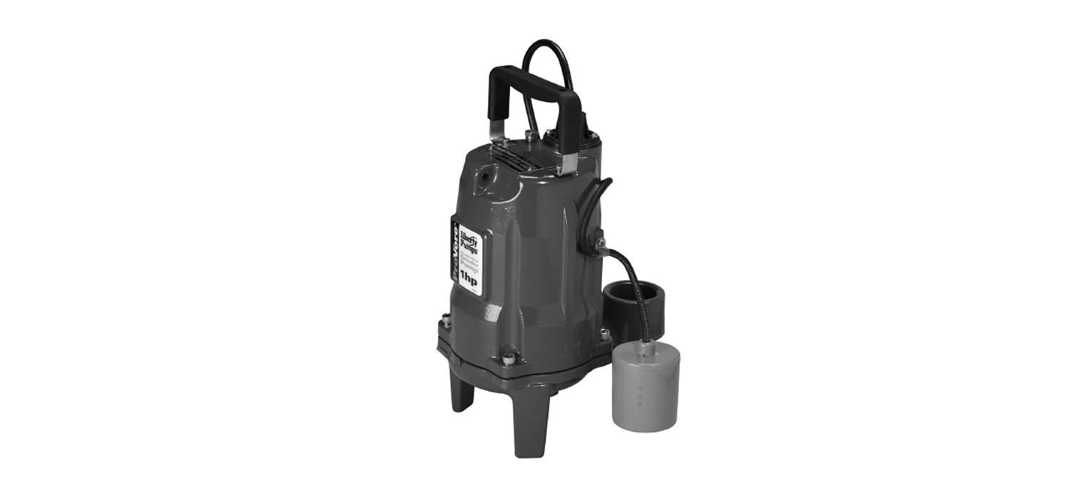
ProVore 1 HP Residential Grinder PumpsInstallation Guide
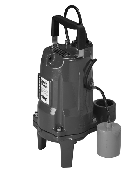
ModelsPRG101-Series : 115 VoltsPRG102-Series: 230 Volts
7000 Apple Tree AvenueBergen, NY 14416ph: 800-543-2550fax: 585-494-1839www.LibertyPumps.com
Installer: Manual must remain with owner/operator.
Keep this manual handy for future reference. For replacement manual, visit LibertyPumps.com, or contact Liberty Pumps at 800-543-2550.Retain dated sales receipt for warranty.
Prior to installation, record information from pump nameplate for future reference:
Model:__________________________Serial:___________________________Mfg Date:________________________Install Date:______________________
Copyright © Liberty Pumps, Inc. 2020 All rights reserved.
Safety Guidelines
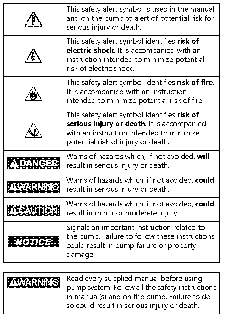
Safety Precautions
RISK OF ELECTRIC SHOCK
- Accidental contact with electrically live parts, items, fluid, or water can cause serious injury or death.
- Always disconnect pump(s) from power source(s) before handling or making any adjustments to either the pump(s), the pump system, or the control panel.
- All installation and maintenance of pumps, controls, protection devices, and general wiring shall be done by qualified personnel.
- All electrical and safety practices shall be in accordance with the National Electrical Code®, the Occupational Safety and Health Administration, or applicable local codes and ordinances.
- Do not remove cord and strain relief, and do not connect conduit to pump.
- Pump shall be properly grounded using its supplied grounding conductor. Do not bypass grounding wires or remove ground prong from attachment plugs. Failure to properly ground the pump system can cause all metal portions of the pump and its surroundings to become energized.
- Do not handle or unplug the pump with wet hands, when standing on damp surface, or in water unless wearing Personal Protective Equipment.
- Always wear dielectric rubber boots and other applicable Personal Protective Equipment (PPE) when water is on the floor and an energized pump system must be serviced, as submerged electrical connections can energize the water. Do not enter the water if the water level is higher than the PPE protection or if the PPE is not watertight.
- Do not lift or carry a pump or a float assembly by its power cord. This will damage the power cord, and could expose the electrically live wires inside the power cord.
- The electrical power supply shall be located within the length limitations of the pump power cord, and for below grade installations it shall be at least 4 ft (1.22 m) above floor level.
- Do not use this product in applications where human contact with the pumped fluid is common (such as swimming pools, fountains, marine areas, etc.).
- Protect the power and control cords from the environment.Unprotected power and control (switch) cords can allow water to wick through ends into pump or switch housings, causing surroundings to become energized.
- Single-phase 208/230V pumps shall only be operated without the float switch by using the circuit breaker or panel disconnect.
- Some products may have internal capacitors that could cause shock. Avoid contact with plug ends after removing from energy source.
- Do not use metal or any other electrical conducting material to raise the float or contact anything inside an electrically live sump pit.
RISK OF FIRE
- Do not use an extension cord to power the product. Extension cords can overload both the product and extension cord supply wires. Overloaded wires will get very hot and can catch on fire.
- This product requires a separate, properly fused and grounded branch circuit, sized for the voltage and amperage requirements of the pump, as noted on the nameplate. Overloaded branch circuit wires will get very hot and can catch on fire. When used, electrical outlets shall be simplex of the appropriate rating.
- For cord replacement: power cord must be of the same length and type as originally installed on the Liberty Pumps product.Use of incorrect cord may lead to exceeding the electrical rating of the cord and could result in death, serious injury, or other significant failure.
- Do not use this product with or near flammable or explosive fluids such as gasoline, fuel oil, kerosene, etc. If rotating elements inside pump strike any foreign object, sparks may occur. Sparks could ignite flammable liquids.
- Sewage and effluent systems produce and may contain flammable and explosive gases. Prevent introduction of foreign objects into basin as sparks could ignite these gases.Exercise caution using tools and do not use electronic devices or have live, exposed electrical circuits in or around basins, open covers and vents.
- Manual pumps that have been factory constructed with a power cord with no male attachment plug must use an approved motor control panel. Do not wire a switch in series with the pump power cord as this can overload the wires.Overloaded wires get very hot and can catch on fire.
- These pumps are not to be installed in locations classified as hazardous in accordance with the National Electric Code®, ANSI/NFPA 70.
RISK OF SERIOUS INJURY OR DEATH
- Energizing the control panel or breaker for the first time is potentially dangerous. Licensed electrical personnel should be present when the panel or breaker is energized for the first time. If faults caused by damage or poor installation practices have not been detected, serious damage, injury or death can result when power is applied.
- Do not modify the pump/pump system in any way.Modifications may affect seals, change the electrical loading of the pump, or damage the pump and its components.
- All pump/pump system installations shall be in compliance with all applicable Federal, State, and Local codes and ordinances.
- Do not allow children to play with the pump system.
- Do not allow any person who is unqualified to have contact with this pump system. Any person who is unaware of the dangers of this pump system, or has not read this manual, can easily be injured by the pump system.
- In 208/230V installations, one side of the line going to the pump is always “hot”, whether the float switch is on or off. To avoid hazards, install a double pole disconnect near the pump installation.
- Vent basin in accordance with local code. Proper venting of sewer and effluent gases alleviates poisonous gas buildup and reduces the risk of explosion and fire from these flammable gases.
- Wear adequate Personal Protective Equipment when working on pumps or piping that have been exposed to wastewater.Sump and sewage pumps often handle materials that can transmit illness or disease upon contact with skin and other tissues.
- Do not enter a pump basin after it has been used. Sewage and effluent can emit several gases that are poisonous.
- Do not remove any tags or labels from the pump or its cord.
- Keep clear of suction and discharge openings. To prevent injury, never insert fingers into pump while it is connected to a power source.
- Do not use this product with flammable, explosive, or corrosive fluids. Do not use in a flammable and/or explosive atmosphere as serious injury or death could result.
- This product contains chemicals known to the State of California to cause cancer and birth defects or other reproductive harm. www.p65warnings.ca.gov.
- A grinder pump contains metal parts that rotate at high speeds. Be careful around pump base while power is connected. Make sure that the pump is either in the tank or clear from people and wires when in operation.
CAUTION:
- This pump has been evaluated for use with water only.
- Wear Personal Protective Equipment as exposed bottom has sharp edges.
Notice:
- Verify a Redundant Check Valve Assembly (curb stop and check valve) is installed between the pump discharge and the street main, as close to the public right-of-way as possible, on all installations to protect from system pressures.
- Do not dispose of materials such as paint thinner or other chemicals down drains. Doing so could chemically attack and damage pump system components and cause product malfunction or failure.
- Do not use pumps with fluid over 140°F (60°C). Operating the pump in fluid above this temperature can overheat the pump, resulting in pump failure.
- Do not use pump system with mud, sand, cement, hydrocarbons, grease, or chemicals. Pump and system components can be damaged from these items causing product malfunction or failure. Additionally, flooding can occur if these items jam the impeller or piping.
- Do not run dry.
- The Uniform Plumbing Code® states that sewage systems shall have an audio and visual alarm that signals amalfunction of the system, to reduce the potential for property damage.
- Do not position the pump float directly under the inlet from drain tile or in the direct path of any incoming water.
- Any PRG-Series system discharge can be reduced to 1-1/4”.
- Keep pump upright.
- At no time should the pump be stored within an incomplete wet pit. The pump should not be placed into the pit until it can be fully operational.
- Do not allow the pump to freeze.
General Information
Before installation, read these instructions carefully. Each pump is individually factory tested to ensure proper performance. Closely following these instructions will eliminate potential operating problems, assuring years of trouble-free service.
PRG-Series pumps are to be used for handling septic tank effluent, sewage, and drain (storm) water.
Provide pump serial number in all correspondence.Pumps are CSA certified to CSA and UL® standards.
Pumps must be serviced at a qualified repair facility approved by Liberty Pumps. No repair work should be carried out during the warranty period without prior factory approval. Any unauthorized field repairs void warranty. Contact Liberty Pumps at 1-800-543-2550 to locate the closest authorized service center.
Operating Constraints
It is extremely important to verify that the pump has been sized correctly for the intended installation. The operating point of the pump must lie within the acceptable range as outlined by the applicable Liberty Pumps performance chart.
Operating the pump outside of the recommended range can invalidate the CSA Certification of the pump and can also cause damage and premature failure. Operating outside of the recommended range can cause the pump to exceed its rated nameplate amp draw, which will void the pump certification. It can also cause motor overheating, cavitation, excessive vibration, clogging, and poor energy efficiency.
Inspection and Storage
Initial Inspection
The pump should be immediately inspected for damage that may have occurred in shipment.
- Visually check the pump and any spare parts for damage.
- Check for damaged electrical wires, especially where they exit the motor housing.
Contact Liberty Pumps customer service to report any damage or shortage of parts.
Storage Before Use
RISK OF ELECTRIC SHOCK
- Protect the power and control cords from the environment.Unprotected power and control (switch) cords can allow water to wick through ends into pump or switch housings, causing surroundings to become energized.
Notice:
- At no time shall the pump be stored within an incomplete wet pit. The pump shall not be placed into the pit until it can be fully operational.
- Do not allow the pump to freeze.
Pumps are shipped from the factory ready for installation and use.Hold the pump in storage if the pump station is not complete.If storage is necessary, the pump should remain in its shipping container. It should be stored in a warehouse or storage shed that has a clean, dry temperature-stable environment where the pump and its container are covered to protect it from water, dirt, vibration, etc. The cord ends must be protected against moisture.Uninstalled pumps that are idle for greater than three months should have cutters and impellers manually rotated once a month to lubricate the seals.
Installed pumps that are idle for greater than one month should have cutters and impellers manually operated through the breaker panel once a month to lubricate the seals. For automatic models, turn off the breaker, unplug the piggyback switch, and plug the pump directly into receptacle. Turn the breaker on for 30 seconds, then turn the breaker off. Plug the piggyback switch back in. Refer to Piggyback Switch Operation on page 8.
Model Specifications
For complete listing of models and their specifications, refer to http://www.LibertyPumps.com/About/Engineering-Specs. Pump nameplate provides a record of specific pump information.
Pump Design
PRG-Series grinder pumps are designed for continuous underwater operation. The motor and pump form a close-coupled, watertight unit. The induction motor is insulated against heat and moisture in accordance with Class B 265°F (130°C) regulations. The motor is protected against damage from water entry by a mechanical type cartridge seal with two silicon carbide faces. The impeller and volute are designed for efficient flow characteristics and clog-free operation. The hardened cutters grind solids and fibrous matter into small particles that can be safely pumped through small diameter piping. For added protection, consider the addition of a Liberty Pumps back-up pump, as well as a high water level alarm in applications where loss of pump function could result in property damage. If an alarm is used, it must be connected to a separate electrical circuit. A duplex pumping system is recommended for critical installations.
Pump System Components
Control Panel
Manual PRG-Series pumps (“M” suffix) require a separate, approved pump control device or panel for automatic operation.Operation will be according to the control selected. Refer to separate manufacturer’s instructions supplied with the unit. Verify the electrical specifications for the control panel properly match those of the pump.
Mounting, installation, and wiring connections are specific to the control panel used. Refer to the manufacturer’s instructions supplied with the unit.
IMPORTANT: When connecting a PRG-Series pump to an existing control panel, verify the panel is correctly sized and equipped for the pump.
Control panels designed for use with the PRG-Series pumps available from Liberty Pumps can be found at [PDF] or contact Liberty Pumps.
Thermostat
A thermal overload (thermostat) is integrally mounted to the motor and wired to shut down the pump if overheating occurs.
The thermostat resets automatically after the pump has cooled.
Float Switches
RISK OF ELECTRIC SHOCK
- Single-phase 208/230V pumps shall only be operated without the float switch by using the circuit breaker or panel disconnect.
Automatic ModelsAutomatic models (“A” suffix) come factory-equipped with a float switch mounted to the pump. These models come with two cords—one to the float switch and the other to the pump motor.The float switch cord has a series (piggyback) plug enabling the pump motor cord to be plugged into the back of it. The purpose of this design is to allow temporary manual operation of the pump. On/Off operation of the pump must be controlled by the circuit breaker. For manual operation, refer to Piggyback Switch Operation on page 8.
In the event of switch failure, the pump cord can be separated and plugged into the electrical outlet, directly bypassing the switch. Pumps should only be operated without the float switch by using the circuit breaker or panel disconnect.
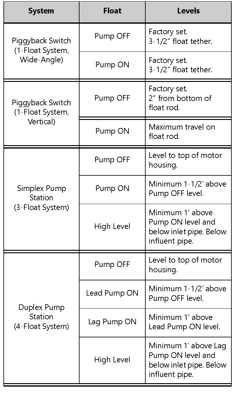
The turn ON level of automatic models is approximately 12” to 16” above the bottom of the basin. The turn OFF level is approximately 6” above the bottom of the basin. Other pumping differentials may be obtained by tethering the switch cord to the discharge pipe. Note: A minimum cord length of 3-1/2” from the tether point to the top surface of the float is required for proper switch operation. If using a differential other than the factory setting, verify the pump shuts off with at least 6” of fluid left in the basin so the impeller remains submerged.
Vertical switch models have pumping differentials pre-set by a rubber stopper placed on the float rod. To reset the pumping differential, slide the stopper to the required height to set the off position. This height Is approximately 2” from the bottom of thefloat rod, or high enough that the float does not have the potential to hang up on the pump or discharge.
Switchless (Manual) Models
RISK OF FIRE
- Manual pumps that have been factory constructed with a power cord with no male attachment plug must use an approved motor control panel. Do not wire a switch in series with the pump power cord as this can overload the wires. Overloaded wires get very hot and can catch on fire.
Manual pumps (“M” suffix) with no switch are intended to be run using an approved liquid level control or approved motor control with correct rating that matches motor input in full load amperes.
If the pump(s) are to be operated by either a simplex or duplex control panel, or other optional control device, follow the manufacturer’s instructions provided with the control panel for power connections.
Float Sequence: Piggyback (Automatic Models)
- As the liquid level in the basin rises, the float tilts, closing the switch. This starts the pump.
- The pump runs until the liquid level falls below the Pump OFF level of the float (factory set at 6”), emptying the basin.
Float Sequence: Simplex (Manual Models)
- As the liquid level in the basin rises, the Pump OFF float tilts, closing the switch. This level must be set at a minimum of 6”. As the liquid level continues to rise, the Pump ON float tilts. This switch closes, starting the pump.
- The pump runs until the liquid level falls below the Pump OFF float, emptying the basin.
- In the event of a malfunctioning float switch, control relay, or pump, the liquid level rises and tilts the High Level Alarm float. The alarm system will activate.
Float Sequence: Duplex (Manual Models)
- As the liquid level in the basin rises, the Pump OFF float tilts, closing the switch. As the liquid level continues to rise, the Lead Pump ON float tilts. This switch closes, starting the lead pump.
- The pump runs until the liquid level falls below the Pump OFF float, emptying the basin.
- On the next rise of the liquid level, the other pump will start on the Lead Pump ON signal. The pumps will continue to alternate their cycles. Note: The ON/OFF float switch differential should be set as to not exceed 12 starts per hour.
- If the liquid level rises to the Lag Pump ON float, the second pump will start. Both pumps will run until the liquid falls below the Pump OFF float, emptying the basin.
- In the event of a malfunctioning float switch, control relay, or pump, the liquid level rises and tilts the High Level Alarm float. The alarm system will activate
Preparation
RISK OF ELECTRIC SHOCK
Always disconnect pump(s) from power source(s) before handling or making any adjustments to either the pump(s), the pump system, or the control panel.
The basin required for effluent and sewage applications must be sealed and vented to meet health and plumbing code requirements. The diameter should be a minimum of 18” and the depth a minimum of 24”. A larger basin may be required depending on local codes and the number of fixture units entering the system.
Pump installation should be at a sufficient depth to ensure that all plumbing is below the frost line. If this is not feasible, remove the check valve and size the basin and/or adjust pump differential to accommodate the additional backflow volume. Consult Liberty Pumps for details on how this should be done.
Prepare Existing Sump [Basin]
If replacing a previously installed pump, prepare the basin by removing the old pump and cleaning any debris from the basin.Inspect all remaining equipment in the basin including piping, valves, and electrical junction boxes (if present) and repair or replace as appropriate.
Prepare New Sump [Basin]
RISK OF SERIOUS INJURY OR DEATH
Locate all overhead and underground utilities before excavating.
Excavate the hole as small as possible, with a minimum recommended 8” diametrical clearance around the tank. Never place the basin directly in contact with rocks or other sharp objects. Place only fine, 1/8” to 3/4” pea gravel or 1/8” to 1/2” washed, crushed stone as bedding between the basin and the hole walls. Do not use sand or native soil as backfill. Properly compact underneath the basin to provide a solid, level base that can support the weight of the filled basin.
Inlet Connection & Initial BackfillUse only fine, 1/8” to 3/4” pea gravel or 1/8” to 1/2” washed, crushed stone around the bottom of the basin to hold it in place.Do not use sand or native soil as backfill.Make the inlet connection as required per basin.
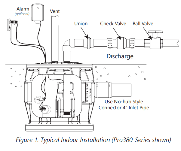
Liberty Pumps P370 and P380-Series Basins have a 4” inlet molded to the side of the tank. This inlet is sized to accept a 4” no-hub type coupling. Connect the gravity drainage line from the fixtures to this hub.
Other Liberty Pumps basins provide a 4” caulking hub or pipe grommet inlet. Hubs utilize caulking material or rubber donuts; grommets are a simple slip-fit. Connect the gravity drainage line from the fixtures to this opening. Other inlet sizes are available, consult factory.
Final BackfillKeep large rocks, clods, and foreign objects out of the backfill material. Only fine, 1/4” to 3/4” pea gravel, or 1/8” to 1/2” washed, crushed stone is recommended. Do not use sand or native soil as backfill. Mound the backfill slightly and allow for natural settling. Provide access to the basin cover for maintenance and service. Compaction of backfill materials must be adequate to ensure the support of the tank, and to prevent movement or settlement.
Note: Do not exert heavy pressure or run heavy equipment on the backfill material as this could cause the tank to collapse.
Table 1. Float Switch Settings
Cutter and Impeller Free Movement Check
Caution: Wear Personal Protective Equipment as exposed bottom hassharp edges.
Do not connect any power to pump until this check is complete. Manually rotate the cutter to check that it spins freely with very little resistance. The cutter is located on the bottom of the pump. The cutter can be carefully rotated by hand, or rotated by inserting a tool into the cutter bolt. If rotating by hand, wear protective gloves as the cutter and cutter plate have sharp edges. The pump can remain upright or can be laid down on its side for easier access to the cutter. Besides verification that the cutter and impeller are freely spinning, rotating the cutter helps to lubricate the shaft seals if the pump has been non-operational for more than a week. It is recommended to rotate the cutter 5–10 full rotations.
Installation
Warnings:
- All installation and maintenance of pumps, controls, protection devices, and general wiring shall be done by qualified personnel.
- All electrical and safety practices shall be in accordance with the National Electrical Code®, the Occupational Safety and Health Administration, or applicable local codes and ordinances.
Figure-1 shows a typical installation. Variations may apply to actual installation.
Electrical Connections
With main power disconnected, complete pump and control wiring connections per manufacturer’s wiring diagrams included with the control panel as applicable. Once wiring is complete, check all wires for unintentional grounds.
Pump
Record information from pump nameplate onto inside cover of these instructions. Complete a visual inspection before lowering into basin.Place pump in basin being sure the mounting interface (i.e., torque stop) is engaged correctly.
Discharge
Make all discharge connections. A check valve is required to prevent the backflow of liquid after each pumping cycle. A gate valve should follow the check valve to allow periodic cleaning of the check valve or removal of the pump. The remainder of the discharge line should be as short as possible with a minimum number of turns to minimize friction head loss. Do not reduce the discharge to below the pump outlet size. Larger pipe sizes may be required to eliminate friction head loss over long runs. Contact Liberty Pumps or other qualified person if questions arise regarding proper pipe size and flow rates.
Vent
Vent basin in accordance with applicable plumbing codes.
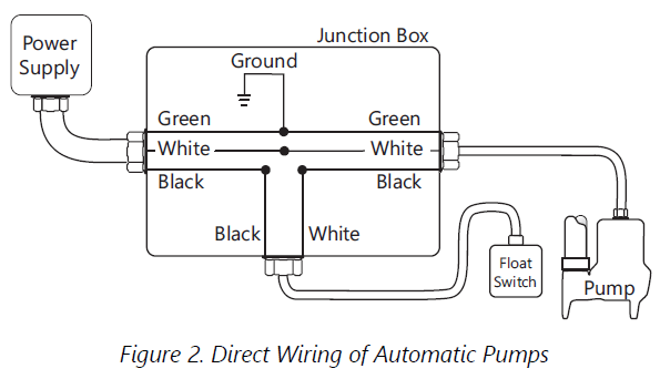
Automatic Pump Direct Wiring
Warning: In 208/230V installations, one side of the line going to the pump is always “hot”, whether the float switch is on or off. To avoid hazards, install a double pole disconnect near the pump installation.
If the pump will be wired directly into a control device or junction box, it is necessary to remove the plug. Qualified personnel shall complete the wiring in accordance with the National Electric Code and applicable local codes. A disconnecting means for the pump shall be located in sight from the pump/basin location. See Figure 2 for direct wire installation of automatic pumps.
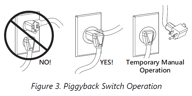
Piggyback Switch Operation
Warning:
- Single-phase 208/230V pumps shall only be operated without the float switch by using the circuit breaker or panel disconnect.
- Some products may have internal capacitors that could cause shock. Avoid contact with plug ends after removing from energy source.
For automatic operation, the two cords should be interconnected and plugged into a separately fused, grounded outlet of proper amp capacity for the selected pump model. Both cords are equipped with 3-prong plugs and must be plugged into a properly grounded 3-wire receptacle. Do not remove the ground prongs.
For manual operation, or in the event of switch failure, the pump cord can be separated and plugged into the electrical outlet directly, bypassing the switch and using the circuit breaker or panel disconnect to operate the pump.
Operation
- Energizing the control panel or breaker for the first time is potentially dangerous. Licensed electrical personnel should be present when the panel or breaker is energized for the first time. If faults caused by damage or poor installation practices have not been detected, serious damage, injury or death can result when power is applied.
Starting System
- Verify all plumbing components in the basin are installed correctly and functional. Verify all valves are open and ready for pump use.
- Double check all wire connections. Re-tighten all factory and field connections.
- Ensure pump has no obstructions.
- With all electrical and mechanical connections complete and secure, turn on power to pump and control panel, if applicable.
- Verify operation of the pump, floats, and alarm circuits.
- Run several cycles of water through the system to verify correct control operation for the installation.
Be certain to complete adequate testing, especially on systems with multiple pumps or custom control configurations.
Maintenance and Troubleshooting
WARNING: RISK OF ELECTRIC SHOCK
- Accidental contact with electrically live parts, items, fluid, or water can cause serious injury or death.
- Always disconnect pump(s) from power source(s) before handling or making any adjustments to either the pump(s), the pump system, or the control panel.
WARNING: RISK OF SERIOUS INJURY OR DEATH
- Wear adequate Personal Protective Equipment when working on pumps or piping that have been exposed to wastewater.Sump and sewage pumps often handle materials that can transmit illness or disease upon contact with skin and other tissues.
- Do not enter a pump basin after it has been used. Sewage and effluent can emit several gases that are poisonous.
Maintenance
Pump should be checked quarterly for corrosion and wear. As the motor is oil-filled, no lubrication or other maintenance is required.Pump is permanently lubricated and cooled by turbine oil. If replacement oil is required, use 0.5 gallons ISO VG 10 turbine oil.
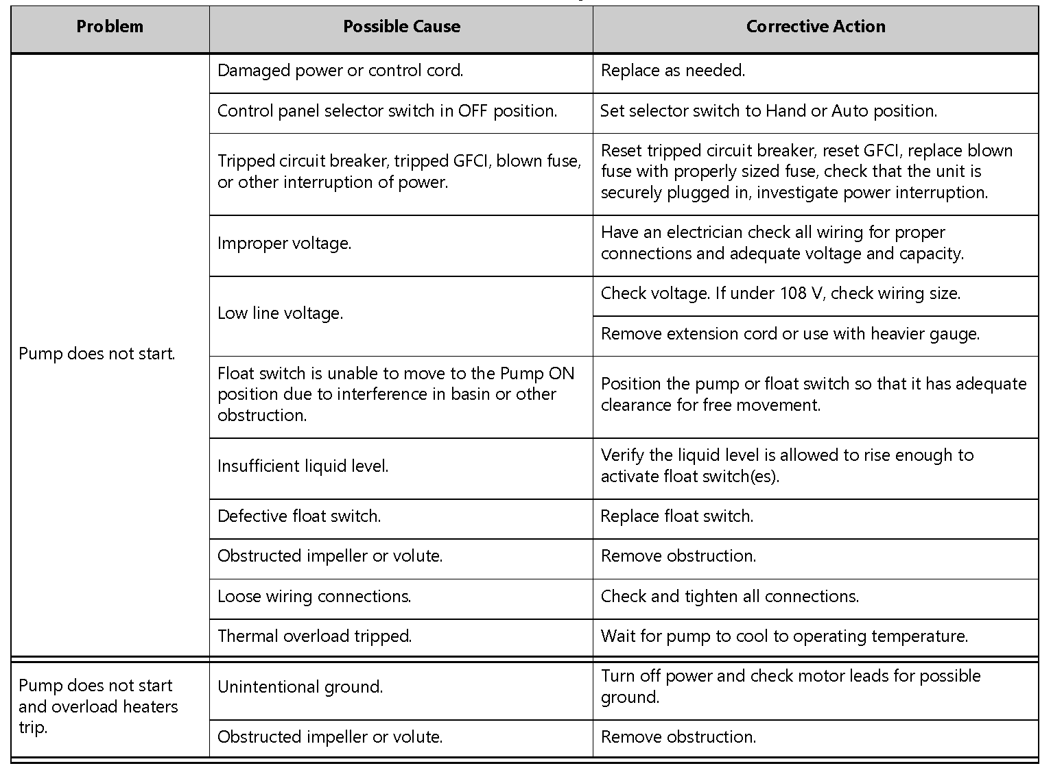
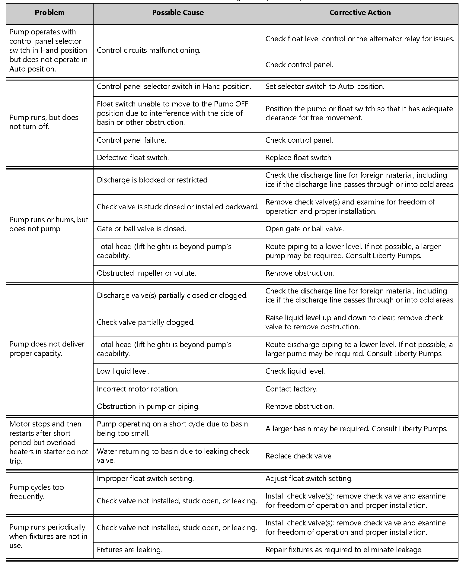
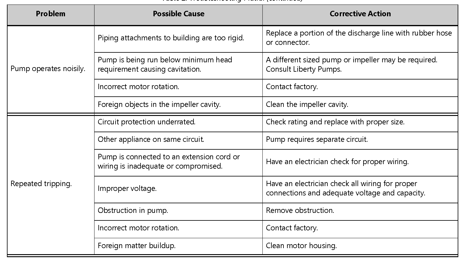
Troubleshooting
No repair work shall be carried out during the warranty period without prior factory approval. To do so may void the warranty.Liberty Pumps, Inc. assumes no responsibility for damage or injury due to disassembly in the field. Disassembly, other than at Liberty Pumps or its authorized service centers, automatically voids warranty.
Table 2. Troubleshooting Matrix
Warranty
Liberty Pumps Wholesale Products Limited Warranty
Liberty Pumps, Inc. warrants that Liberty Pumps wholesale products are free from all factory defects in material and workmanship for a period of three (3) years from the date of purchase (excluding batteries). The date of purchase shall be determined by a dated sales receipt noting the model and serial number of the pump. The dated sales receipt must accompany the returned pump if the date of return is more than three years from the date of manufacture noted on the pump nameplate.
The manufacturer’s sole obligation under this Warranty shall be limited to the repair or replacement of any parts found by the manufacturer to be defective, provided the part or assembly is returned freight prepaid to the manufacturer or its authorized service center, and provided that none of the following warranty-voiding characteristics are evident:
The manufacturer shall not be liable under this Warranty if the product has not been properly installed, operated, or maintained per manufacturer instructions; if it has been disassembled, modified, abused, or tampered with; if the electrical cord has been cut, damaged, or spliced; if the pump discharge has been reduced in size; if the pump has been used in water temperatures above the advertised rating;
if the pump has been used in water containing sand, lime, cement, gravel, or other abrasives; if the product has been used to pump chemicals, grease, or hydrocarbons; if a non-submersible motor has been subjected to moisture; or if the label bearing the model and serial number has been removed.
Liberty Pumps, Inc. shall not be liable for any loss, damage, or expenses resulting from installation or use of its products, or for indirect, incidental, and consequential damages, including costs of removal, reinstallation or transportation.
There is no other express warranty. All implied warranties, including those of merchantability and fitness for a particular purpose, are limited to three years from the date of purchase. This Warranty contains the exclusive remedy of the purchaser, and, where permitted, liability for consequential or incidental damages under any and all warranties are excluded.

7000 Apple Tree AvenueBergen, NY 14416ph: 800-543-2550fax: 585-494-1839www.LibertyPumps.com
References
[xyz-ips snippet=”download-snippet”]