![]()
SP-460 OWNER’S MANUAL

![]() Product may vary slightly from the item pictured due to model upgradesRead all instructions carefully before using this product. Retain this owner’s manual for future reference.NOTE: This manual may be subject to updates or changes. Up to date manuals are available through our website at www.lifespanfitness.com.au
Product may vary slightly from the item pictured due to model upgradesRead all instructions carefully before using this product. Retain this owner’s manual for future reference.NOTE: This manual may be subject to updates or changes. Up to date manuals are available through our website at www.lifespanfitness.com.au
IMPORTANT SAFETY INSTRUCTIONS
WARNING – Read all instructions before using this machine.It is important your machine receives regular maintenance to prolong its useful life. Failing to regularly maintain your machine may void your warranty.
Please keep this manual with you at all times
- a. It is important to read this entire manual before assembling and using the equipment. Safe and effective use can only be achieved if the equipment is assembled, maintained, and used properly.Please note: It is your responsibility to ensure that all users of the equipment are informed of all warnings and precautions.b. Before starting any exercise program you should consult your doctor to determine if you have any medical or physical conditions that could put your health and safety at risk, or prevent you from using the equipment properly. Your doctor’s advice is essential if you are taking medication that affects your heart rate, blood pressure or cholesterol level.
- c. Be aware of your body’s signals. Incorrect or excessive exercise can damage your health. Stop exercising if you experience any of the following symptoms: pain, tightness in your chest, irregular heartbeat, and extreme shortness of breath, lightheadedness, dizziness, or feelings of nausea. If you do experience any of these symptoms, you should consult your doctor before continuing with your exercise program.
- d. Keep children and pets away from the equipment. This equipment is designed for adult use only.
- e. Use the equipment on a solid, flat-level surface with a protective cover for your floor or carpet. To ensure safety, the equipment should have at least 0.5 meters of free space all around it.
- f. Before using the equipment, check that the nuts and bolts are securely tightened. If you hear any unusual noises coming from the equipment during use and assemble, stop immediately. Do not use the equipment until the problem has been rectified.
- g. Wear suitable clothing while using the equipment. Avoid wearing loose clothing that may get caught in the equipment or that may restrict or prevent movement.
- h. This equipment is designed for indoor and family use only.
- i. Care must be taken when lifting or moving the equipment so as not to injure your back.
- j. Always keep this instruction manual and assembly tools at hand for quick reference.
- k. The equipment is not suitable for therapeutic use.
- l. There are many functions of the computer, which value will show when using the equipment according the amount of exercise, here warmly remind you that the value of heart pulse just give you some reference.
CARE INSTRUCTIONS
IMPORTANTa. All nuts and bolts are to be checked and tightened on a regular basis. This includes pedals and other moving parts. Failure to do so may cause damage to your threads and void your warranty.b. Lubricate moving joints after periods of usagec. Be careful not to damage plastic or metal parts of the machine with heavy or sharp objectsd. The machine can be kept clean by wiping it down using dry cloth
Battery Usagea. Batteries are to be installed or replaced by adult onlyb. Do not use rechargeable batteries. Do not mix different battery types. Do not mix old and new batteries. Do not mix alkaline, standard (Carbon-Zinc), or rechargeable (Nickel-Cadmium) batteriesc. Remove batteries when product is not in use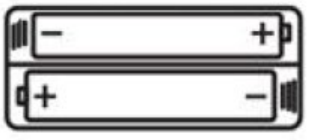 d. Remove exhausted batteries from product and dispose of in accordance with the manufacturer’s recommendatione. Do not attempt to recharge non-rechargeable batteriesf. Batteries are to be inserted with correct polarityg. The supply terminals are not to be short-circuited
EXPLODED DIAGRAM
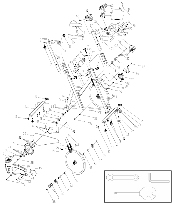
PARTS LIST
| NO |
NAME |
QUANTITY |
SPEC |
| 1 | PEDAL | 1 | JD-301 (9/16″ ) |
| 2 | END CAP1 | 5 | 60*30*1.5 |
| 3 | CARRIAGE BOLT | 4 | GB/T 12-1988 M8*42 |
| 4 | REAR STABILIZER | 1 | WELDING |
| 5 | FLAT WASHER | 4 | GB/T 95-2002 8 |
| 6 | DOMED NUT | 4 | GB/T 802-1988 M8 (H=16mm) |
| 7 | SPRING ADJUSTMENT KNOB | 3 | φ57*62 (M16*1.5) |
| 8 | PLASTIC SLEEVE | 3 | 53.5*23.5*1.5 |
| 9 | LOCK NUT | 2 | M33*1*4 |
| 10 | VERTICAL SEAT POST | 1 | WELDING |
| 11 | END CAP2 | 1 | 53.5*23.5*1.5 |
| 12 | SEAT POST | 1 | WELDING |
| 13 | SEAT | 1 | DD-2681 |
| 14 | STOPPER | 4 | φ32*37/(M8X25) |
| 15 | FRONT STABILIZER | 1 | WELDING |
| 16 | MAIN FRAME | 1 | WELDING |
| 17 | HANDLEBAR POST | 1 | WELDING |
| 18 | HANDLE BAR | 1 | WELDING |
| 19 | SPRING WASHER | 4 | GB/T 859-1987 8 |
| 20 | BOLT | 8 | GB/T 70.2-2000 M8*15 |
| 21 | HANDLEBAR COVER | 1 | 115*89*75 (60g) |
| 22 | B0TTLE HOLDER | 1 | 117*85*90 |
| 23 | B0TTLE | 1 | XS-003(1#) 500ML |
| 24 | BRAKE KNOB | 1 | 112*32*7 |
| 25 | ADJUSTMENT KNOB | 1 | φ38*79 |
| 26 | LITTLE PLASTIC RING | 1 | 14*8*9 |
| 27 | PLASTIC RING | 2 | φ20*φ9*3 |
| 28 | FIXING NUT 1 | 2 | GB/T 6177.2-2000 M10*1.25 |
| 29 | CRANK END CAP | 2 | φ23*7.5 |
| 30 | SHEET IRON | 1 | δ5 |
| 31 | LOCK NUT | 7 | GB/T 889.1-2000 M8 |
| 32 | CHAIN WHEEL | 1 | A7K-16 1/2″*1/8″ 16T (1.37″ ) |
| 33 | LEFT CRANK | 1 | 170*27 |
| 34 | CRANK COVER | 1 | φ56*28 |
| 35 | BEARING | 2 | 6004ZZ |
| 36 | RIGHT CRANK | 1 | 170*27 |
| 37 | RIGHT PROTECT COVER | 1 | 156*80*174 (85g) |
| 38 | FIXING NUT 2 | 2 | GB/T 802-1988 M12X1.25 (H=16mm) |
| 39 | FIXING BOLT | 2 | M6*54 |
| 40 | NUT | 2 | GB/T 889.1-2000 M6 |
| 41 | SCREW 1 | 15 | GB/T 845-1985 ST4.2*19 |
| 42 | SCREW 2 | 2 | GB/T 15856.1-2002 ST4.2X19 |
| 43 | SCREW 3 | 2 | GB/845-85 ST4.8X13 |
| 44 | OUTER CHAIN COVER | 1 | 714*301*60 |
| 45 | LITTLE CHAIN COVER | 1 | 108*37*3 (7g) |
| 46 | AXIS | 1 | φ20*162 |
| 47 | LONG FIXING TUBE | 1 | φ25*φ20.5*41 |
| 48 | SHORT FIXING TUBE | 1 | φ25*φ20.5*9 |
| 49 | INNER CHAIN COVER | 1 | 454*288*6 |
| 50 | CHAIN | 1 | 12.7 ,106 |
| 51 | CHAIN WHEEL | 1 | P=12.7,Z=52T |
| 52 | BRAKE | 1 | 2PCS 130mm |
| 53 | BOLT | 1 | GB/T 70.1-2000 M6*20 |
| 54 | BRAKE PLASTIC | 2 | 82*41*19 |
| 55 | BOLT | 2 | GB/T 5780-2000 M8*40 |
| 56 | WHEEL | 2 | φ50*23 |
| 57 | NUT | 4 | GB/T 41-2000 M8 |
| 58 | FIXING NUT 2 | 2 | M12X1.25 H=6 |
| 59 | FIXING TUBE | 1 | φ16*φ12.1*35 |
| 60 | BEARING | 2 | 6001ZZ |
| 61 | FLYWHEEL | 1 | φ453*72(18KG) |
| 62 | FLYWHEEL SHAFT | 1 | φ12*160 |
| 63 | WOOLLY BLOCK | 2 | 78*38*6 |
| 64 | COMPUTER HOLDER | 1 | WELDING |
| 65 | COMPUTER | 1 | ST-6527(ST-7607) |
| 66 | FIXING NUT | 2 | 27*M20*1 (5mm ) |
| 67 | FLYWHEEL COVER | 1 | φ59*35 |
| 68 | SCREW 4 | 1 | ST2.9*9.5 |
| 69 | LEFT PROTECT COVER | 1 | 157*73*157 (85g) |
| 70 | END CAP | 2 | φ25*1.5 |
| 71 | FOAM GRIP | 2 | φ23*φ29*465 |
| 72 | SENSOR | 1 | SR-202 |
| 73 | PULSE WIRE | 1 | L=800 |
| 74 | PULSE | 2 | |
| 75 | SCREW 5 | 2 |
GB/845-85 ST4.2X25 |
ASSEMBLY INSTRUCTIONS
STEP 1: PREPARATIONA. Before assembling make sure that you will have enough space around the item.B. Use the present tooling for assembling.C. Before assembling please check whether all needed parts are available (at the above of this instruction sheet you will find an explosion drawing with all single parts (marked with numbers) which this item consists of.
STEP 2:
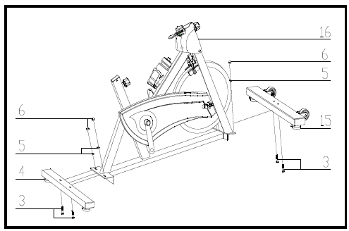
1. Attach the Front Stabilizer (pt.15) to the Main Frame (pt.16) using two sets of Ø8 Flat Washers (pt.5), M8 Domed Nut (pt.6) and M8*45 Carriage bolt (3).2. Attach the Rear Stabilizer (pt.4) to the Main Frame (pt.16) using two sets of Ø8 Flat Washers (pt.5), M8 Domed Nut (pt.6) and M8*45 Carriage bolt (3).
STEP 3:
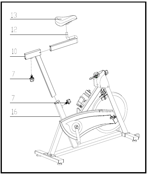
1. Slide the Vertical Seat Post (pt.10) into the seat post housing on the main frame (pt.16).2. Slide the Seat Post (pt.12) into the Vertical Seat Post (pt.10). You will have to loosen the knurled section of Spring Adjustment knob (pt.7) and pull the knob back and then select the desired height. Release the knob and retighten the knurled portion.3. Now fix the Seat (pt.13) to the Seat Post (pt.12) as shown, and tighten the bolts around the screws under the seat.
STEP 4:
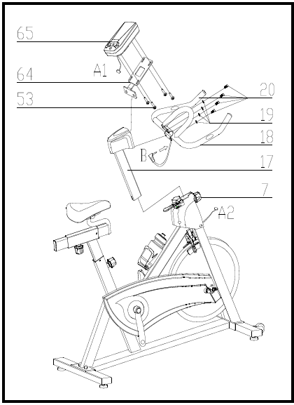
1. Slide the Handlebar Post (pt.17) into the handlebar post housing on the main frame. You will have to loosen the knurled section of the Spring Adjustment Knob (pt.7) and pull the knob back and then select the desired height. Release the knob and retighten the knurled portion.2. Remove the bolts and spring washer from the Handlebar Post (pt.17).3. Attach the Handlebar (pt.18) with 4xØ8 the Spring Washer (pt.19) and M8*15 Bolts (pt.20).
PLEASE ENSURE THE HANDLEBAR IS FIXED TIGHTLY4. Attach the Computer (pt.65) onto the Computer Holder (pt.64) using 4 bolts (pt.53). Be sure to connect the plug (A1 & A2)
STEP 5:
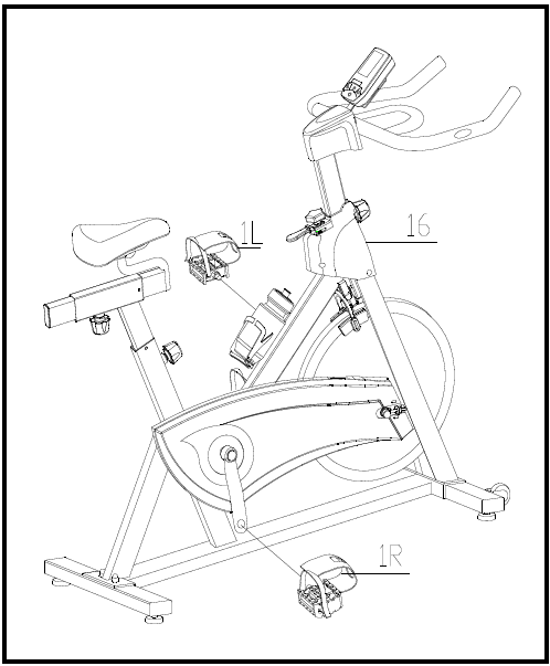
1. The Pedals (pt.1 L & pt.1 R) are marked “L” and “R” – Left and Right. Connect them to their appropriate crank arms. The right crank arm is on the right- hand side of the cycle as you sit on it.Note that the Right pedal should be threaded on clockwise and the Left pedal anticlockwise.
ADJUSTMENT INSTRUCTIONS
Vertical Seat AdjustmentTo adjust the seat height, slacken the spring knob on the vertical post stem on the main frame and pull back the knob. Position the vertical seat post for the desired height so that holes are aligned, then release the knob and retighten it.Horizontal Seat AdjustmentTo move the seat forward in the direction of the handlebar or backwards away from it, loosen the adjusting knob and washer and pull the knob back. Slide horizontal seat post into desired position. Align holes and then retighten the adjusting knob.Handlebar HeightTo adjust the handlebar height, slacken the spring knob and secondary knob and pull both knobs back. Slide the handlebar post along the housing on the main frame to the desired height and, with the holes aligned correctly, tighten the spring adjusting knob and then the secondary knob.
COMPUTER OPERATION
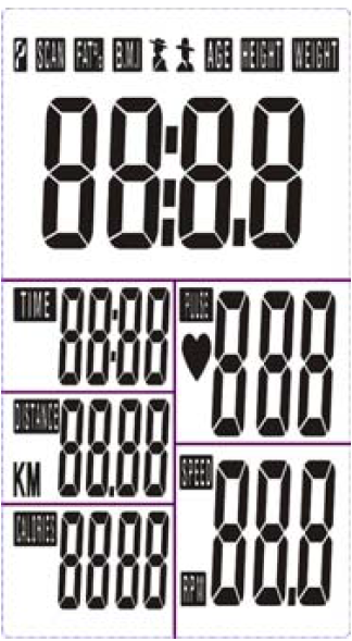
BUTTON FUNCTIONMODE: Press the “Mode” button for mode selection. This button also functions as an enter button during setup.SET: To set the value of TIME, DISTANCE, CALORIES and PULSE. You can hold the button down to increase the value quickly. (The computer must be in stop condition.)RESET: The user may press the “RESET” button to reset each function: Time, Distance, Calorie, Pulse. Hold this button down for 2 seconds for total reset. (If batteries are replaces, all values will reset to ZERO automatically.)RECOVERY: Enable the heart rate recovery function after training.FUNCTIONSSCAN: Cycles through all functions from TIME, DISTANCE, CALORIES, PULSE, RPM/SPEED.RPM: Displays the Rotation Per Minute. The RPM and SPEED will rotate every 6 seconds after exercise starts.SPEED: Displays current training speed. Maximum speed is 99.9 KM/H.TIME: Accumulates total workout time when no value is preset. Time will count up from 00:00 to maximum 99:59.Count down: Press the SET button to set a preset time between 0:00 to 99:50. Time will count down from the preset time to 00:00.DISTANCE: Accumulates total distance from 00:00 up to 99.99 KM when no value is preset.Count down: Press the SET button to set a preset distance between 00:00 to 99.99 KM. Distance will count down from the preset time to 00:00.CALORIES: Accumulates calories burnt from 0 to 9999 calories when no value is preset.Count down: Press the SET button to set a preset calorie goal between 0 and 9990. Calories will count down from the preset value to 0.(This data is a rough guide for comparison of different exercise sessions. It must not be used for medical treatment purposes.)PULSE: The user may preset pulse by pressing SET button. (This data is a rough guide for comparison of different exercise sessions. It must not be used for medical treatment purposes.)
OPERATION ORDER
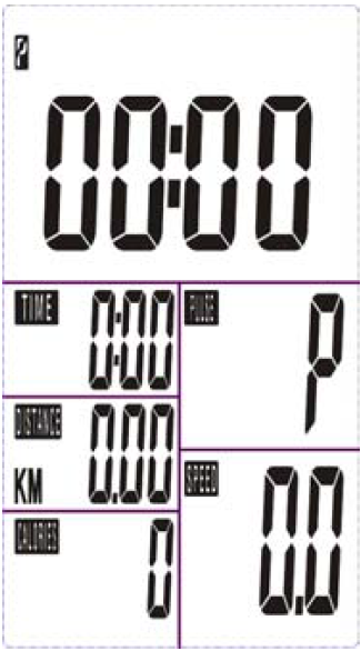
- Install 2 x 1.5V UM-4 or AAA batteries. The screen will display in accordance with (Picture A) and “Beep” at the same time. It will then enter to standby mode (Picture B).Picture A Picture B

- Use the SET button to preset values for TIME/DISTANCE/CALORIES/PULSE. SET alters the value for a specific category. MODE confirms a set value.
- The values RPM/SPEED/TIME/DISTANCE/CALORIES/PULSE will start increasing as soon as the sensor receives a signal that you are pedalling. If preset values have been set, the monitor will ‘beep’ for 8 seconds once the function counts down to 0. The function will then immediately count up from 0 if the workout is continued. During this, press MODE to confirm and skip to the next setup option.
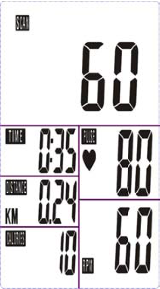
- In SCAN mode as shown in Picture C,RPM/SPEED/TIME/DISTANCE/CALORIES/PULSE will alternate every 6 seconds.Picture Picture C
- The MODE button may also be used to select a single function to be displayed on the main display excluding RPM and SPEED. These two functions will always alternate automatically.
RECOVERY
a. Press the “RECOVERY” button to activate the RECOVERY function. In this function, only PULSE and TIME will display whilst other functions will be inactive.The Sensor Input will not be available.TIME will start to count down from “00:60”. The Pulse signal will blink according to the user’s pulse. When countdown reaches “0”, it will show F1~F6.
| F1 | Outstanding |
| F2 | Excellent |
| F3 | Above Average |
| F4 | Average |
| F5 | Below Average |
| F6 | Poor |
b. The LCD will display as follows: (RECOVERY start condition & end condition)
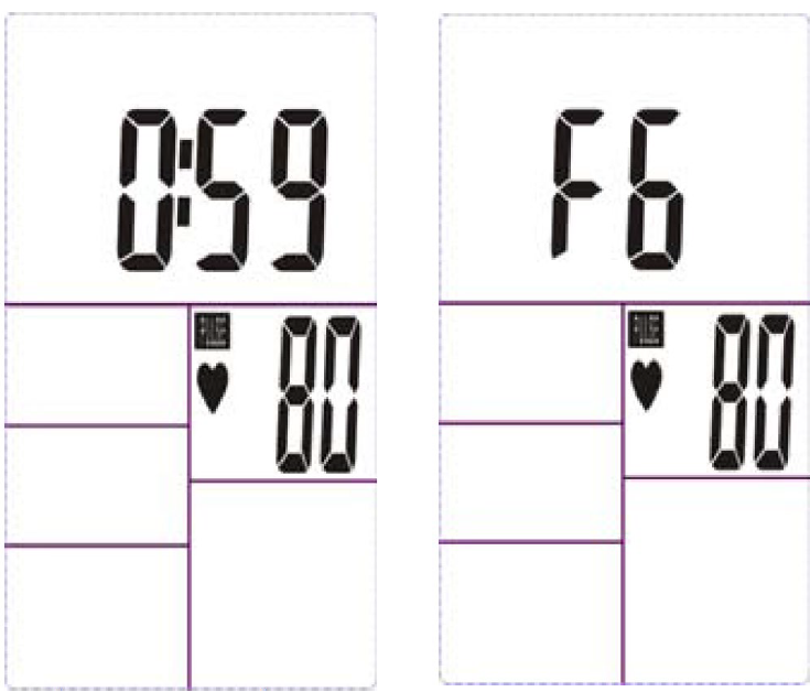
c. If the countdown to 00:00 is not completed and there is no pulse signal, F6 will show.d. If you press the RECOVERY button prior to the countdown reaching 00:00, this will end the function and no result will show.
NOTE1. After being inactive for 4 minutes, the main screen will turn off and will display the clock automatically.2. If the computer displays abnormally, please re-install the battery and try again.Battery Spec: 1.5V UM-4 or AAA (2PCS).
EXERCISE GUIDE
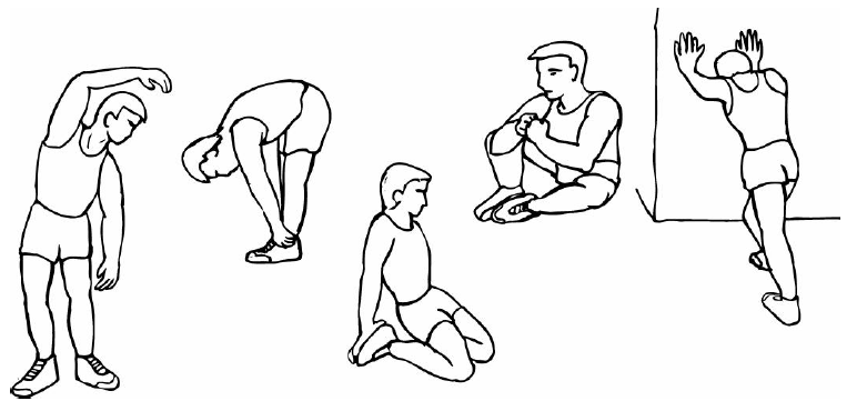
PLEASE NOTE: Before beginning any exercise program, consult your physician. This is important especially if you are over the age of 45 or individuals with pre-existing health problems.The pulse sensors are not medical devices. Various factors, including the user’s movement, may affect the accuracy of heart rate readings. The pulse sensors are intended only as an exercise aid in determining heart rate trends in general.Exercising is great way to control your weight, improving your fitness and reduce the effect of aging and stress. The key to success is to make exercise a regular and enjoyable part of your everyday life.The condition of your heart and lungs and how efficient they are in delivering oxygen via your blood to your muscles is an important factor to your fitness. Your muscles use this oxygen to provide enough energy for daily activity. This is called aerobic activity. When you are fit, your heart will not have to work so hard. It will pump a lot fewer times per minute, reducing the wear and tear of your heart.So as you can see, the fitter you are, the healthier and greater you will feel.Warm-upStart each workout with 5 to 10 minutes of stretching and some light exercises. A proper warm-up increases your body temperature, heart rate and circulation in preparation for exercise. Ease into your exercise.
Training Zone ExerciseAfter warming up, increase the intensity to your desired exercise program. Be sure to maintain your intensity for maximum performance. Breathe regularly and deeply as you exercise-never hold your breath.Cool DownFinish each workout with a light jog or walk for at least 1 minute. Then complete 5 to 10 minutes of stretching to cool down. This will increase the flexibility of your muscles and will help prevent post-exercise problems.
Workout Guidelines
TARGET ZONE
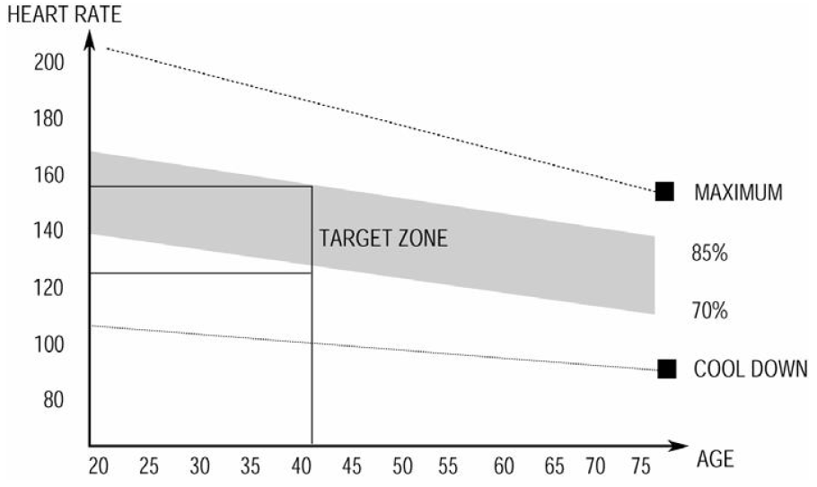
THIS IS HOW YOUR PULSE SHOULD BEHAVE DURING GENERAL FITNESS EXERCISE. REMEMBER TO WARM UP AND COOL DOWN FOR A FEW MINUTES.The most important factor here is the amount of effort you put in. The harder and longer you work, the more calories you will burn. Effectively this is the same as if you were training to improve your fitness, the difference is the goal.
WARRANTY
AUSTRALIAN CONSUMER LAWMany of our products come with a guarantee or warranty from the manufacturer. In addition, they come with guarantees that cannot be excluded under the Australian Consumer Law. You are entitled to a replacement or refund for a major failure and compensation for any other reasonably foreseeable loss or damage. You are entitled to have the goods repaired or replaced if the goods fail to be of acceptable quality and the failure does not amount to a major failure. Full details of your consumer rights may be found at www.consumerlaw.gov.auPlease visit our website to view our full warranty terms and conditions:http://www.lifespanfitness.com.au/warranty-repairs
Warranty and Support:Please email us at [email protected] for all warranty or support issues.For all warranty or support-related inquiries an email must be sent before contacting us via any other means.
Head Office and Customer Service:Global Fitness and Leisure Pty Ltd17 Fordson RdCampbellfieldVIC, 3061AustraliaPH: 03 9357 2166
Hand Pulse Technology
This product comes equipped with hand pulse sensors which are used to pick up tiny EKG/ECG signals that run through the body when your heartbeats. These electrical EKG/ECG signals are very small and that they must be amplified 1000 times to make the signal useful for the computer to display your pulse.
To ensure proper operation:– The user must maintain good, consistent contact on all four sensors– The user’s skin cannot be too dry or too wetOther factors that could affect the reading:– Change of grip on the sensors (during slow pace walking and up to running)– Tightening of hand muscles will produce small electrical signals– Static electricity charges from the air or from walking on the treadmillEKG/ECG Sensors may filter through actual EKG/ECG signals and “Noise” factors that may affect the reading. This will cause the pulse reading to be delayed and will take longer to update the display as the heart rate changes. Too much noise will create an incorrect reading. Medical conditions or having no electrical signal in the hands are other factors that may affect pulse readings as well.These are limitations of hand pulse technology and even the most expensive systems (which can cost upwards of $3,000) used in hospitals have the same problems. The difference is that a patient in a hospital is not running on a treadmill. Hand pulse technology works well on stationary exercise machines like bikes and even elliptical cross trainers but are not perfect on a treadmill. We offer treadmills with a wireless heart rate receiver which may be a more accurate option.To test if your hand pulse sensors are working up to specification, hold them while standing on the side step rails, not walking, and see if the reading is more in line with what you would expect. This will eliminate the movement and static electricity factors. If your hands are dry, then wet them slightly (saliva works as a great conductor if this doesn’t bother you).For more information, please contact our Lifespan Technical Support Departmentwww.lifespanfitness.com.au[email protected]
![]()
References
[xyz-ips snippet=”download-snippet”]