LIGHTOBJECT Motorized Z Table User Guide
Introduction
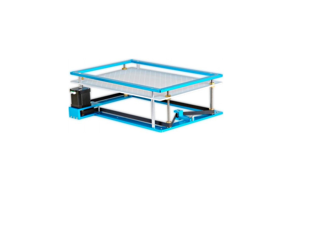
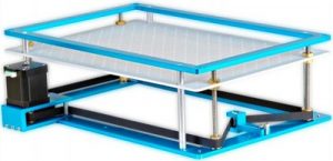
Thank you for purchasing the mini powered Z-table/bed. This mini-powered bed is designed to perfectly fit the “k40” small desktop CO2 laser machine. The unit comes as a kit, so it already comes with a lot of parts you need to build it. The purpose of this power bed is to allow for height adjustment to get better cutting or engraving. This manual will walk you through successfully assembling of your kit.
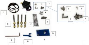
What is included
| 1 Bottom Frame (Blue) |
A |
4 Threaded-rods with T-screws and nut G | |
| 1 Top Frame (Blue) |
B |
1 Belt |
H |
| 1 Bed |
C |
1 Stepper Motor |
I |
| 1 Belt-tensioner |
D |
8 Bearings |
J |
| 4 poles |
E |
4 Washers |
K |
| Screws |
F |
1 Allen key |
L |
| 1 motor bracket |
M |
Spare parts |

Steps to Assemble
Step 1:Unscrew the three flat head screws to remove the frame from the motor bracket “M”.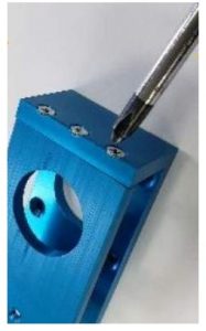 Step 2:Fastening the stepper motor “I” to the motor bracket “M” with screws “F1”.
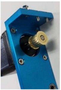
Step 3:Place the belt “H’ to the motor pulley. Then, fasten the frame back to the motor bracket with the 3 screws shown in Step 1. Step 4:Put back the two bearings and shafts to the frame. Note: the belt should be coming out in between the rollers
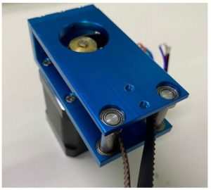
Step 5:Fasten the motor bracket assembly with screws “F2” to the bottom frame “A”.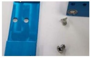
 Note: Please pay attention to the direction. Motor should lie on the outside of the bottom frame.
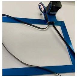
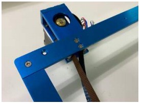
Step 6:Use Allen key “L” to fasten belt-tensioner “D” to the bottom frame “A” with screws “F3”.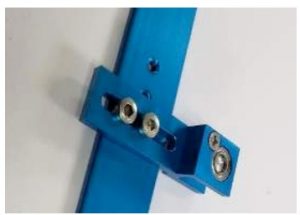
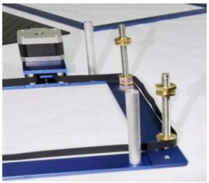
Step 7:Fasten the poles “E” to the bottom frame “A” with the 4 screws “F4” that already attached to the poles. Keep the other 4 screws for later use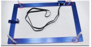
 Step 8:Put 4 bearings “J” to the 4 slots on the bottom frame “A”.
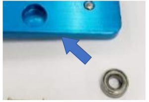
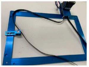
Step 9:Spread the belt around the frame. Insert threaded rod “G” to the bearings with the belt surrounding the pully.
 Step 10:Adjust the position of belt-tensioner “D” to accomplish the desire tension on the belt.
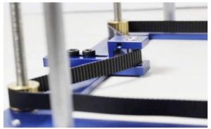
Step 11:Remove the upper lock nuts.Note: Threaded side of the T-nuts should face up.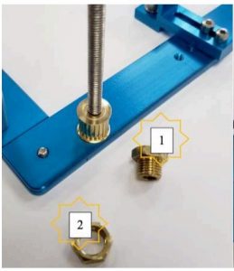
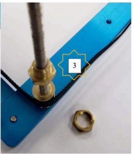 Important: The T-nut will provide support to the bed, so make sure that all T nuts are LEVEL and also have enough space underneath such that the bed doesn’t lay on the stepper motor’s bracket.
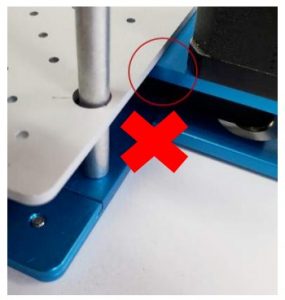 Step 12:Lay the bed “C” on the 4 T-nuts.Important: Make sure The bed doesn’t wobble or lay on the stepper motor’s upper frame. Fix these problems by adjusting the height of the T-nuts properly. The bed should go thru all threaded-rods and poles.
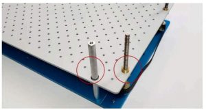 Step 13:Tighten the upper lock nuts.
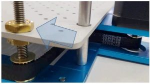 Step 14:Place the bearings on top of each of the threaded-rods.
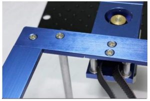
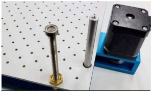 Step 15:Put the upper frame by gently pushing the bearing in the blind holes.
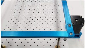
Step 16:Before fasten the top frame with screws “F4”, insert a washer “K” on top of each pole.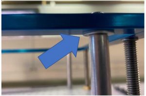 Congratulations!! You’ve finally finish assembling your Motorized Z Table/Bed
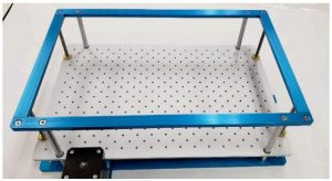
Wire coloring connection
Wiring the stepper motor. For wiring the 2-phase motor:Green/Black wires to A+/A- on stepper driver.Blue/Red wires to B+/B- on stepper driver.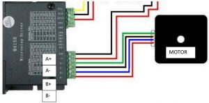 Note:- For drivers with PUL + and DIR, connect those to +5V on controller board. Those with DIR-, connect it to DIR on the controller board and for PUL, connect to PUL-on controller board.
[xyz-ips snippet=”download-snippet”]