![]() Quick Start Guide
Quick Start Guide
 HDMI-TPS-RX220AK
Important Safety Instructions
Please read the supplied safety instruction document before using the product and keep it 0available for future reference.
Introduction
Thank you for choosing Lightware HDMI-TPS-RX220AK receiver. The device offers seamless HDBaseT™ integration with additional Lightware product lines and developments, including TPS matrices and 25G boards. The device receives digital video at a resolution up to 4K, as well as audio and control up to 170 meters over a single CAT cable. Furthermore, the device utilizes control over USB KVM and can be remotely powered over TPS link with PoE (IEEE 802.3af), a useful array of features to further simplify the operation for system integrators and users.
![]()
The product is compatible with any third-party HDBaseT™ device.HDBaseT™ and the HDBaseT Alliance logo are trademarks of the HDBaseT Alliance.Compatible DevicesThe receiver is compatible with other Lightware TPS devices, matrix TPS and TPS2 boards, 25G boards, as well as third-party HDBaseT-extenders, displays, but not compatible with the phased-out TPS-90 extenders. The receiver is PoE-compatible (Power over Ethernet, can be powered remotely via CATx cable) but the device can receive only power and cannot send power to other PoE-compatible devices.
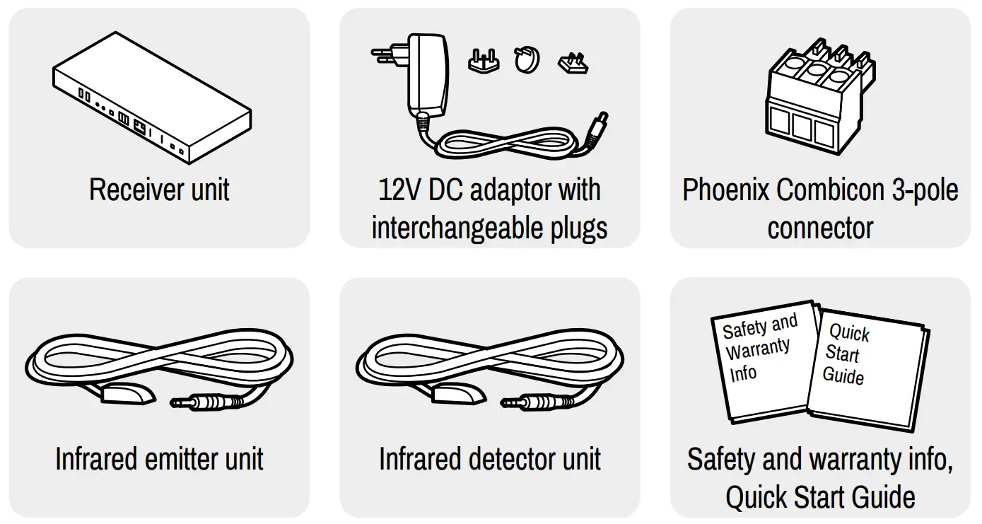
Box Contents
Front View
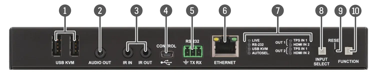
- USB A-type connectorsUSB KVM ports for HID-compatible devices (preferably keyboard and mouse).
- Analog audio outputTRS (3.5mm jack) connector for unbalanced analog audio output.
- Infrared connectors2 TRS (3.5mm jack) connectors for Infrared units (IR IN for the detector, IR OUT for the emitter)
- USB-mini connectorUSB interface for LDC connection to control and configure the device.
- RS-232 connector3-pole Phoenix connector for serial communication.
- Ethernet connectorRJ45 connector for remote controlling and firmware upgrade purposes.
- Status LEDsLEDs give feedback about the current status of the device, interface ports, and the AV crosspoint settings.
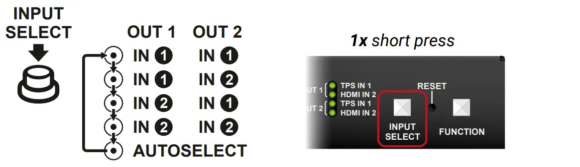
- Input select buttonPushing the button selects a video source for HDMI out 1 and 2 ports.
- Reset buttonPushing the button reboots the unit.
- Function buttonSpecial functions are available with this button (boatload mode, DHCP settings, restore factory default settings, condition launching in Event Manager).
Status LEDsLIVE
- OFF: device is not powered.
- BLINKING (slow; 1 sec): device is powered and operational.
- BLINKING (fast; 0,5 sec): device is in bootload (firmware upgrade) mode.
- ON: device is powered but not operational.
RS-232
- OFF: RS-232 ports (local and link) are in Pass-through mode.
- BLINKING: Command Injection mode is active.
- ON: RS-232 ports (local and link) are in Control mode.
USB KVM
- OFF: USB is not enumerated.
- ON: USB is enumerated.
AUTOSEL. (AUTOSELECT)
- OFF: Autoselect function is not active.
- ON: Autoselect is enabled on any input.
Input Select LEDs
- OFF: Input is not selected.
- BLINKING: Input is selected but no signal is present.
- ON: Signal is present on the selected input.
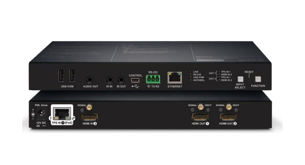
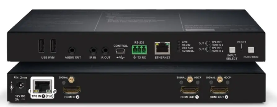
Rear View
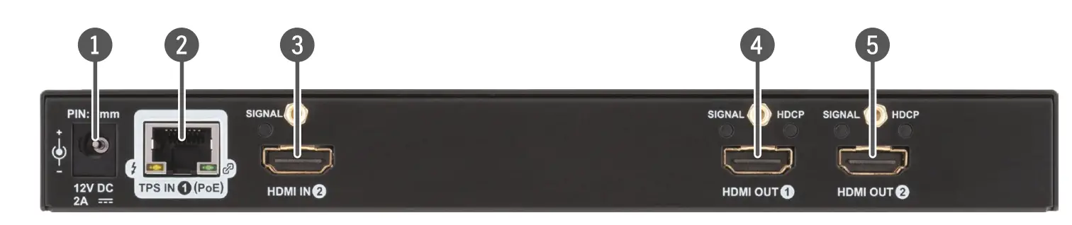
- 12V DC input connector12V DC input for local powering.
- TPS input portTPS input port for the compatible transmitter device (extender / matrix / board).
- HDMI input portHDMI input port for DVI or HDMI signal. Connect an HDMI cable between the receiver and the source device.
- HDMI out 1 portHDMI output 1 port for the sink device. The source of the port can be selected with the Input Select button. Connect HDMI cables between the receiver and the sink devices.
- HDMI out 2 portHDMI output 2 port for the sink device. The source of the port can be selected with the Input Select button. Connect HDMI cables between the receiver and the sink devices.
Rear Panel LEDsTPS Input LEDs![]() ON: remote power receiving (PoE) is active.
ON: remote power receiving (PoE) is active.![]() OFF: no TPS link between transmitter and receiver.BLINKING: device is in low power mode or in Ethernet fallback mode.ON: TPS link is active.HDMI Input / Output – SIGNAL LED
OFF: no TPS link between transmitter and receiver.BLINKING: device is in low power mode or in Ethernet fallback mode.ON: TPS link is active.HDMI Input / Output – SIGNAL LED
- OFF: input or output signal is not present or muted.
- ON: signal is present.
HDMI Output – HDCP LED
- OFF: output signal is not HDCP-encrypted.
- BLINKING: non-HDCP capable device is connected, the encrypted signal is replaced with a red screen.
- ON: output signal is HDCP-encrypted.
Connecting Steps
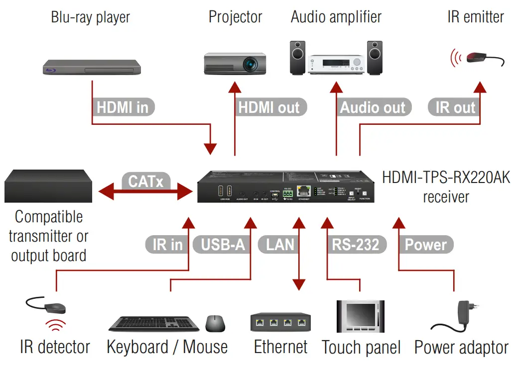
CATxConnect the receiver and the TPS transmitter/matrix output board by a CATx cable via the TPS connector.HDMI inConnect the receiver and the HDMI source device (e.g. Blu-ray player) by an HDMI cable via the HDMI input port.HDMI outConnect the sink devices (e.g. projector) to the HDMI output 1 and 2 ports by HDMI cables.Audio outOptionally for analog audio output: connect an audio device (e.g. audio amplifier) to the analog audio output port by an audio cable.IR inOptionally for Infrared extension:IR out
- Connect the IR emitter to the IR OUT port of the receiver, and/or
- Connect the IR detector to the IR IN port of the receiver.
USB-AOptionally for USB HID extension: connect the USB HID devices to the receiver (preferably mouse and keyboard).LANOptionally connect the receiver to a LAN in order to control the device.RS-232Optionally for RS-232 extension: connect a controller/controlled device (e.g. touch panel) to the RS-232 port.PowerConnect the power adaptor to the DC input on the receiver first, then to the AC power socket. See the available powering options of the receiver on the Powering Options section on the other side.
Mounting
To mount the receiver Lightware supplies optional accessories for different usage. There are two kinds of mounting kits with similar fixing methods. The receiver has two mounting holes with an inner thread on the bottom side. Fasten the device by the screws enclosed with the accessory.

The Under-desk double mounting kit makes it easy to mount a single device on any flat surface, e.g. furniture. The 1U high rack shelf provides mounting holes for fastening two half-rack or four quarter-rack-sized units. Pocket-sized devices can also be fastened on the shelf. To order mounting accessories please contact [email protected].Using different (e.g. longer) screws may cause damage to the device.The receiver is half-rack-sized.
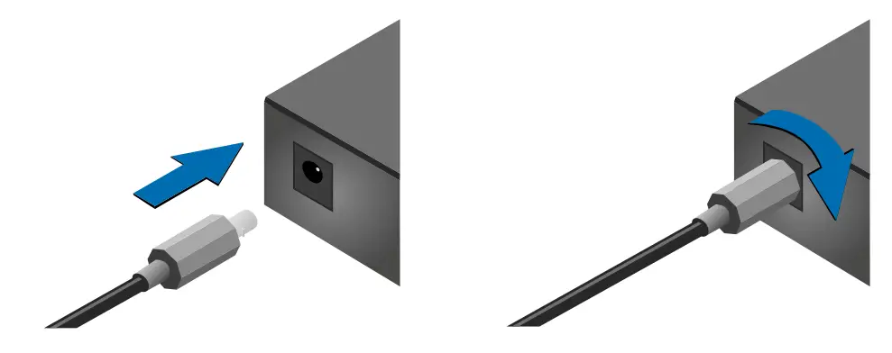
Locking DC Plug
Twist 90° clockwise to lock.
Powering Options
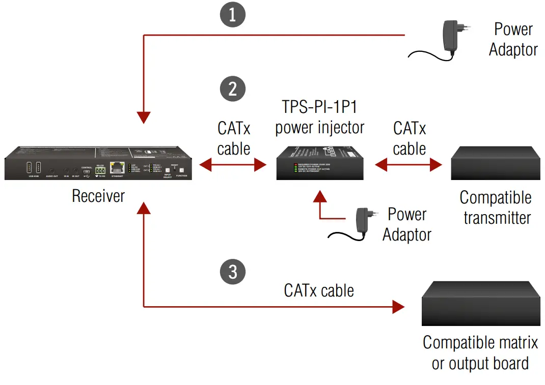
- Using local PSUConnect the power adaptor to the DC input on the receiver first, then to the AC power socket.2 Using PoE with connecting a transmitterConnect the TPS IN (PoE) port of the receiver to the TPS+PoE output port of the TPS-PI-1P1 power injector by a CATx cable as well as connect the TPS output port of the transmitter to the TPS port of the TPS-PI-1P1 by a CATx cable.3 Using PoE with connecting a matrix switcher or an output boardConnect the TPS IN (PoE) port of the receiver to the PoEcompatible TPS output port of the matrix or output board by a CATx cable.
In case of connecting the receiver to an output board of the matrix always connect an external PSU to the board. For detailed information please read the user’s manual of the matrix.The Ethernet port does not support PoE. Only the TPS port supports the PoE function.If both remote and local power sources are connected, remote power will be used.
Types of IR Connectors (1/8” TRS / TS)

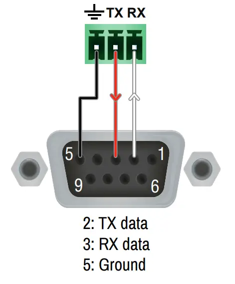
Wiring Guide for RS-232 Data Transmission
The receiver is built with a 3-pole Phoenix connector. See the examples below of connecting to a DCE (Data Circuit-terminating Equipment) or a DTE (Data Terminal Equipment) type device:
|
Lightware device and a DCE |
Lightware device and a DTE |
| D-SUB 9 – Phoenix |
D-SUB 9 – Phoenix |
 |
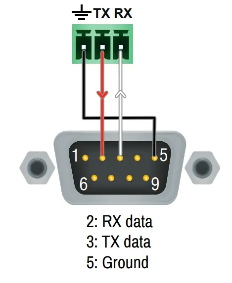 |
For more information about the cable, wiring sees the user’s manual of the device or the Cable Wiring Guide on our website www.lightware.com/support/guides-and-white-papers.
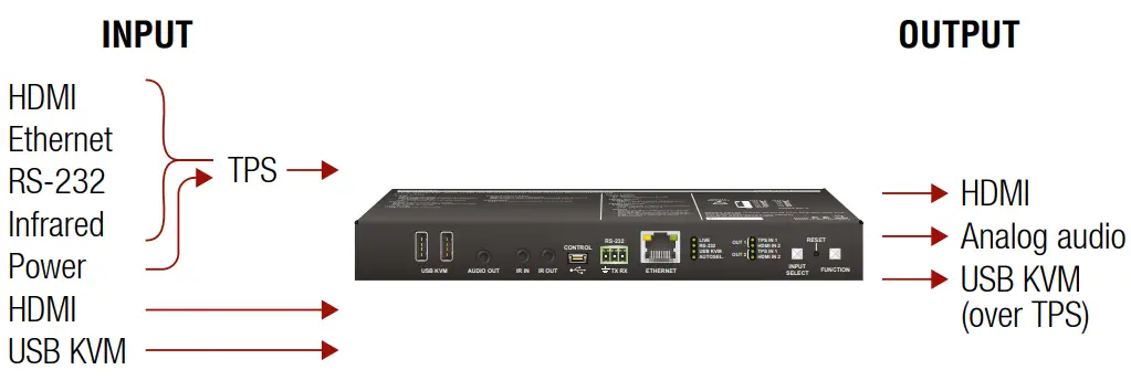
TPS Receiver Concept
HDMI-TPS-RX220AK is a multifunctional TPS receiver with an audio de-embedding function and USB KVM feature. The device receives audio/video, Ethernet, RS-232, and Infrared signals via the TPS input port and can be powered by another extender due to the PoE-capability. The receiver can be controlled via USB, Ethernet, RS-232, or Infrared and is able to control third-party devices via the RS-232, Ethernet, Infrared and USB KVM.
- + Local USB
- + Ethernet
- + RS-232
- + Infrared
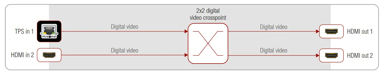
Port Diagrams
Video Port Diagram
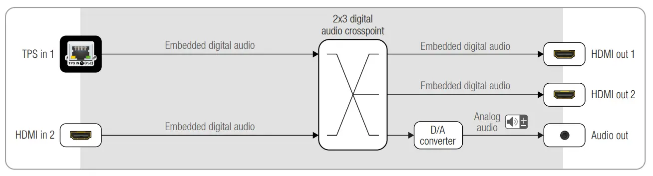
 Audio Port Diagram
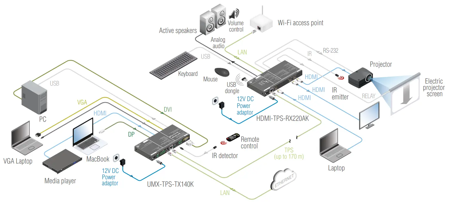
Typical Application Diagram
Front Panel Control
Set the dynamic IP address
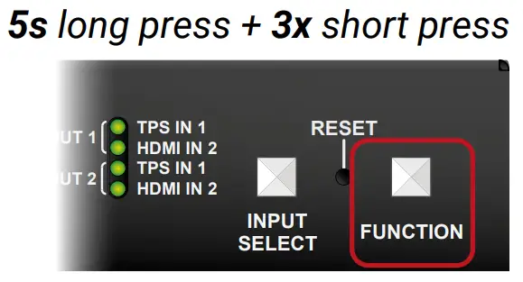
- Keep the Function button pressed for 5 seconds; all front panel LEDs start to blink.
- Release the button, then press it 3 times quickly. DHCP is now enabled.Restore Factory Default Settings

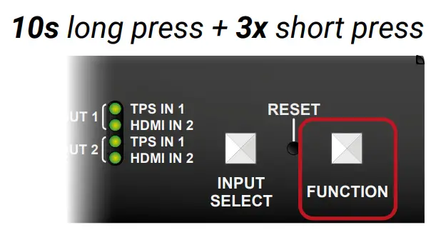
- Keep the Function button pressed for 10 seconds; after 5 seconds front panel LEDs start to blink but keep the button pressed; the LEDs start to blink faster 5 seconds later.
- Release the button, then press it 3 times quickly; the following factory default settings are restored:
|
Network settings |
|
| IP address (static) | 192.168.0.100 |
| Subnet mask | 255.255.255.0 |
| Static gateway | 192.168.0.1 |
| DHCP | Disabled |
| TCP/IP port nr. LW2 I LW3 | 1000116107 |
|
Video crosspoint settings |
|
| 01 (HDMI out 1) | Ι1(Tps in 1) |
| 02 (HDMI out 2) | Ι2 (HDMI in 2) |
|
Video port properties |
|
| Autoselect | Disabled |
| Input IPS mode | Auto |
| Emulated EDID on the inputs | Factory #47: Universal HDMI PCM |
|
Audio switcher setting |
|
| 03 (Analog audio out) | I1(de-embedded audio stream of TPS in 1) |
|
Analog audio output port properties |
|
| Volume | 0.00 dB (100%) |
| Balance | 0 (center) |
|
RS•232 settings |
|
| RS•232 mode | Passthrough |
| Control protocol | LW2 |
| Port setting | 57600 BAUD, 8, N, 1 |
| Command injection port (locatilink) | 80011 8002 |
Input Selection for the HDMI Output Ports
The source signal for the HDMI output ports can be selected by pushing the Input Select button. Five preprogrammed crosspoint states can be applied:
Software Control – Using Lightware Device Controller (LDC)
The device can be controlled from a computer through the Ethernet, USB, or RS-232 ports using Lightware Device Controller. Please download the application from www.lightware.com, install it on a Windows PC or a macOS, and connect to the device via the Ethernet port.The IP address of the unit is static (default): 192.168.0.100., DHCP is disabled.
 report this ad
Further InformationThe document is valid with the following firmware version: 1.4.0The User’s manual of this appliance is available on www.lightware.com.See the Downloads section on the dedicated product page.Contact Us[email protected]+36 1 255 3800[email protected]+36 1 255 3810![]() Lightware Visual Engineering LLC.Peterdy 15, Budapest H-1071, HungaryDoc. ver.: 1.019200043
Lightware Visual Engineering LLC.Peterdy 15, Budapest H-1071, HungaryDoc. ver.: 1.019200043
References
[xyz-ips snippet=”download-snippet”]