LIGHTWARE MMX8x8 HDMI 4K A USB20 Matrix Switcher
Important Safety Instructions
Please read the supplied safety instruction document before using the product and keep it available for future reference.
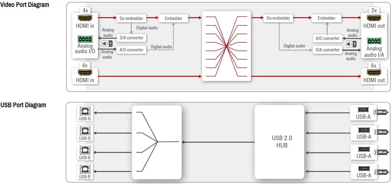
IntroductionMMX8x8-HDMI-4K-A-USB20 is a standalone matrix switcher offering eight HDMI 1.4 inputs and eight independent HDMI 1.4 outputs. Additional analog audio input and output connectors allow to embed a different audio signal in the HDMI stream or breakout the audio signal from the HDMI stream on the output. USB 2.0 connectivity allowing easy switching across four USB peripherals and four hosts. 4K / UHD (30Hz RGB 4:4:4, 60Hz YCbCr 4:2:0), 3D capabilities and HDCP are fully supported. Unique USB functions allow seamless integration in Unified Communication and small Video Conference rooms.
VentilationTo ensure the correct ventilation and avoid overheating let enough free space around the appliance. Do not cover the appliance, let the ventilation holes free on both sides.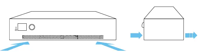
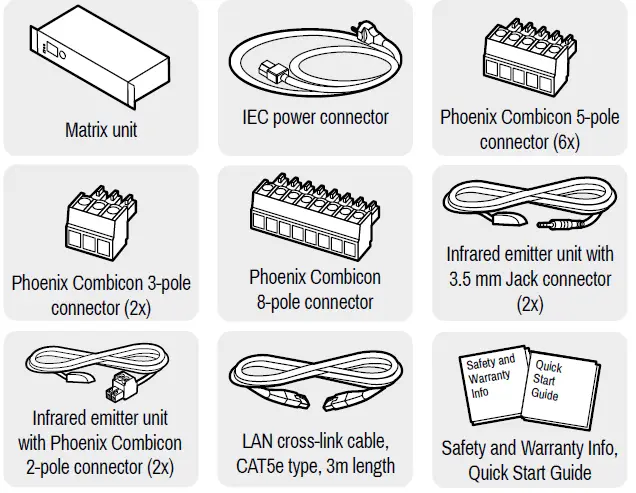
Box Contents
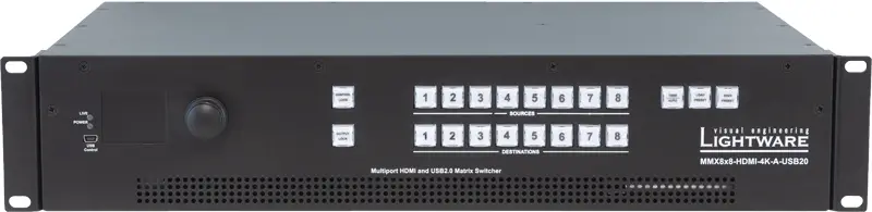
Front View
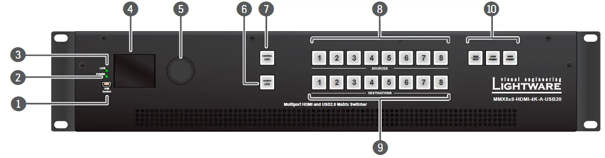
- USB mini-B port: USB mini-B port for controlling the unit locally by Lightware Device Controller software.
- POWER LED: on Power LED indicates that the unit is powered on.
- LIVE LED: blinking slow The unit is on and operates properly. blinking fast The unit is in bootload mode.
- LCD screen: Displays the front panel menu. Basic settings are available.
- Jog dial knob: Browse the menu by turning the knob, click on the desired item to check or change it.
- Output Lock: Locking one or more outputs.
- Control Lock: Disable or enable front panel operations. Red light means the switching and function buttons are disabled.
- Sources: Buttons to select an input, to select a preset number or to view the state of the selected input port.
- Destinations: uttons to select an output or to view the state of an output.
- Function Buttons: Switching between working modes (Take / Autotake) and performing Preset operations.
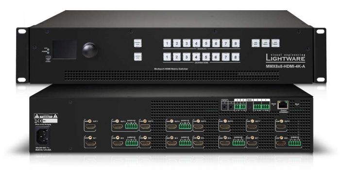
Rear View
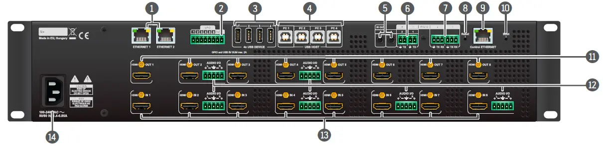
- Ethernet ports: The two RJ45 connector for Ethernet (to control the unit or to pass-through). They are in the same local network.
- GPIO port: 8-pole Phoenix connector for configurable general purpose input/output ports.
- USB-A ports: The four USB 2.0 Type-A ports for connecting USB peripherals.
- USB-B ports: The four USB 2.0 Type-B ports for connecting USB hosts.
- Infra output ports: 3.5 mm TRS connectors (Jack plugs) for infra signal transmission.
- Serial/Infra output ports: 2-pole Phoenix connectors (2x) for IR output or TTL output serial signal.
- RS-232 ports: 3-pole Phoenix connectors (2x) for bi-directional RS-232 communication.
- Reset button: Reboots the matrix; the same as switching it off and on again.
- Control Ethernet port: RJ45 connector to control the matrix via LAN.
- Boot button: Reset or power on the device while keep pushing the hidden button takes the matrix in bootload mode.
- HDMI outputs: HDMI output connectors for sink devices.
- Audio I/O ports: 5-pole Phoenix connector for balanced analog audio; depending on the configuration, it can be input or output. Output audio is the de-embedded HDMI signal from the nearby HDMI port.
- HDMI inputs: HDMI input ports (8x) for sources.
- AC connector: Standard IEC connector accepting 100-240 V, 50 or 60 Hz.
Mounting Options – Standard Rack Installation
Two rack ears are supplied with the product, which are fixed on left and right side as shown in the picture. The default position allows mounting the device as a standard rack unit installation.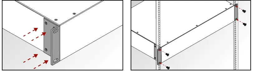
The matrix switcher is 2U-high and one-rack wide.
- Always use all the four screws for fixing the device ears to the rack rail. Choose properly sized screws for mounting. Keep minimum two threads left after the nut screw.
Pin Assignment of 2-pole IR Emitter Connector (1/8” TS)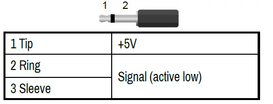
Serial Output Voltage Levels (TTL and RS-232)
| TTL* | RS-232 | |
| Logic low level | 0 .. 0.25V | 3 V .. 15 V |
| Logic high level | 4.75 .. 5.0V | -15 V .. -3 V |
*Using a receiver with at least 1k impedance to any voltage bewt een 0V and 5V to get the voltages.
Connecting Steps
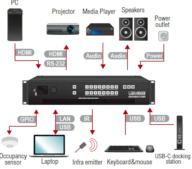
HDMI Connect an HDMI source (e.g. PC) to the HDMI input port.HDMI Connect an HDMI sink (e.g projector) to the HDMI output port.Audio Optionally for analog output ports: connect an audio device (e.g. speakers) to the analog audio output port by an audio cable.Audio Optionally for audio output ports: connect the audio source (e.g. media player) to the audio input port by an audio cable.RS-232 Optionally connect a serial device (e.g projector) to the 3-pole Phoenix connector to transmit RS-232 commands.Power Connect the power cord to the AC power socket to the matrix unit.GPIO Optionally connect a device (e.g. occupancy sensor) to the GPIO port.IR Optionally connect the infra emitter to the infra output port (2-pole Phoenix or 1/8” Stereo Jack connector) to transmit infra signal.LAN Optionally connect the UTP cable (straight or cross, both are supported) in order to control the matrix switcher via the Lightware Device Controller software.USBUSB mini-B: Optionally connect the USB cable in order to control the matrix switcher via the Lightware Device Controller software.USB Type-A: Optionally connect the USB device (e.g. keyboard and mouse).USB Type-B: Optionally connect the USB host (e.g. USB-C docking station).
Powering the device is recommended as the final step.
Software Control – Using Lightware Device Controller (LDC)The device can be controlled from a computer using the Lightware Device Controller software. The application is available at www.lightware.com, install it on a Windows PC or a macOS and connect to the device via LAN, USB, or RS-232.
Firmware UpgradeLightware Device Updater 2 (LDU2) is an easy and comfortable way to keep your device up-to-date. Establish the connection to the device via Ethernet. Download and install LDU2 software from the company’s website www.lightware.com where you can find the latest firmware package as well.
Front Panel Operations – LCD Menu and Navigation
The front panel has a color LCD showing the most important settings and parameters. The jog dial control knob can be used to navigate between the menu items or change the value of a parameter. The knob can be pressed to enter a menu or edit/set a parameter.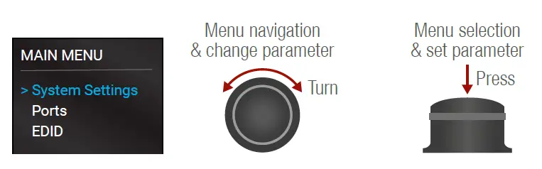
Front Panel Operations – AUTOTAKE Mode
Press and hold the Take button for two seconds to change between Take and Autotake modes. When the Take button continuously illuminates green, Autotake mode is selected. Autotake mode is useful when immediate actions must be take or fast switching is needed between sources on a particular destination. In this mode switching occurs immediately upon pressing one of the input selector buttons.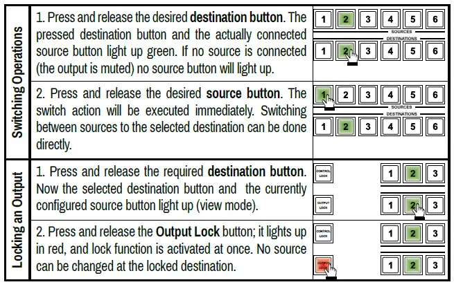
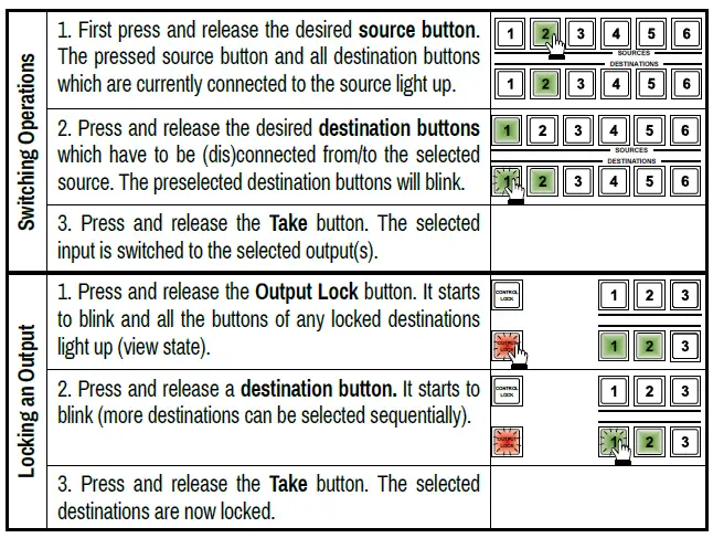
Front Panel Operations – AUTOTAKE Mode
Take mode allows the user to connect or disconnect multiple outputs to an input at once. This mode is useful when multiple switching is necessary. The commands are only realized when the Take button is pressed.
Typical Application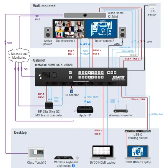
Factory Default Settings
| IP address | 192.168.0.100 |
| LW3 / LW2 port number | 6107 / 10001 |
| Video I/O Ports | Unmuted, unlocked |
| Crosspoint setting | Input 1 on all outputs |
| HDCP enable (input) | Enable |
| HDCP mode (output) | Auto |
| Signal Type | Auto |
| Power 5V mode | Auto |
| Emulated EDID | F47 – (Universal HDMI, all audio) |
| Audio mode | HDMI audio passthrough |
| Analog audio input levels | Volume (dB): 0.00; Balance: 0; Gain (dB): 0.00 |
| Analog audio output levels | Volume (dB): 0.00; Balance: 0 |
| RS-232 port setting | 57600 BAUD, 8, N, 1, Command injection mode |
| Control protocol (RS-232) | LW2 |
| RS-232 port nr. | 8001, 8002, 8003, 8004 |
| IR operation mode | Command injection mode |
| IR port nr. | 9001, 9002, 9003, 9004 |
| Selected USB Host (USB-B port) | PC1 |
| 5V Enabled on USB Device (USB-A ports 1-4) | Enable |
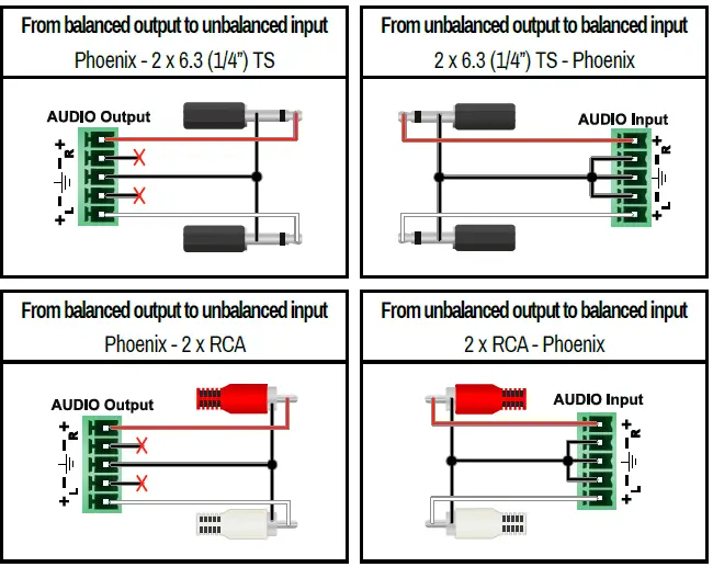
Audio Cable Wiring Guide
MMX8x8-HDMI-4K-A-USB20 matrix is built with 5-pole Phoenix input and output connectors. See below a few example of the most common assembling cases.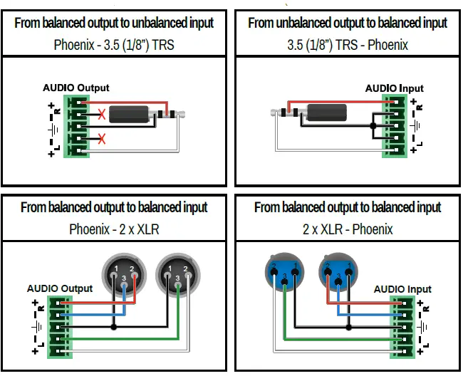
 report this ad
Further InformationThe document is valid with the following firmware version: 1.2.2 The product brief and further information of this appliance is available on www.lightware.com. See the Downloads section on the website of the product.Contact Us[email protected]are.com+36 1 255 3800[email protected]+36 1 255 3810Lightware Visual Engineering LLC. Peterdy 15, Budapest H-1071, Hungary
References
[xyz-ips snippet=”download-snippet”]