![]()
1200m Fibre Optic DisplayPort 1.2 ExtenderUser Manual![]()
No. 38417© LINDY Group – SECOND EDITION (January 2021)
Safety Instructions
![]() ! WARNING!Please read the following safety information carefully and always keep this document with the product.Failure to follow these precautions can result in serious injuries or death from electric shock, fire or damage to the product.Touching the internal components or a damaged cable may cause electric shock, which may result in death.This device is a switching type power supply and can work with supply voltages in the range 100 – 240 VAC For worldwide usability four different AC adapters are enclosed: Euro type, UK type, US/Japan type and Australia/New Zealand type. Use the appropriate AC adapter as shown in the picture and ensure it is firmly secured in place and does not detach by pulling before installing it into a power socket.To reduce risk of fire, electric shocks or damage:
! WARNING!Please read the following safety information carefully and always keep this document with the product.Failure to follow these precautions can result in serious injuries or death from electric shock, fire or damage to the product.Touching the internal components or a damaged cable may cause electric shock, which may result in death.This device is a switching type power supply and can work with supply voltages in the range 100 – 240 VAC For worldwide usability four different AC adapters are enclosed: Euro type, UK type, US/Japan type and Australia/New Zealand type. Use the appropriate AC adapter as shown in the picture and ensure it is firmly secured in place and does not detach by pulling before installing it into a power socket.To reduce risk of fire, electric shocks or damage:
- Do not open the product nor its power supply. There are no user-serviceable parts inside.
- Only qualified servicing personnel may carry out any repairs or maintenance.
- Never use damaged cables.
- Do not expose the product to water or places of moisture.
- Do not use this product outdoors it is intended for indoor use only.
- Do not place the product near direct heat sources. Always place it in a well-ventilated place.
- Do not place heavy items on the product or the cables.
- Please ensure any adapters are firmly secured and locked in place before inserting into a wall socket
Instructions for Use of Power Supply
To connect the adapterSlide the desired plug adapter into the power supply until it locks into place.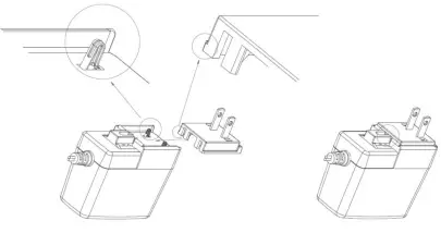
To remove the adapter
Press both sides of the latch as indicated belowWhile pressed, slide the plug adapter for the power supply.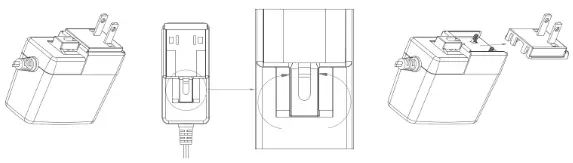
Introduction
Thank you for purchasing the 1200m Fibre Optic DisplayPort 1.2 Extender. This product has been designed to provide trouble-free, reliable operation. It benefits from both a LINDY 2-year warranty and free lifetime technical support. To ensure correct use, please read this manual carefully and retain it for future reference.The Lindy 1200m Fibre Optic DisplayPort 1.2 Extender is the professional solution for extending DP 1.2 signals over increased distances which are not possible with traditional copper-based systems, using a single standard duplex LC OS1 single mode (9/125µm) fiber optic cable.
Package Contents
- Transmitter Unit
- Receiver Unit
- 2 x 5VDC 3A Multi-country Power Supply (UK, EU, US & AUS), Screw Type Barrel Size: 5.5/2.1mm
- Lindy Manual
Features
- Supports resolutions up to 3840× 4:4:4 10bit
- Uncompressed video transmission for lossless video extension
- High immunity to RF and EM Interference via galvanic isolation and high resistance
- HDCP and DPCP Pass-through
- EDID Pass-through
- Supports up to 7.1CH audio pass-through
- Screw Type DC Plug for a secure connection (5.5/2.1mm)
- Premium, metal black housing
Specification
- Requires a single duplex LC OS1 Single-Mode Fibre Cable (9/125μm)
- Extends 21.6Gbps signals up to 1200m (3936.96ft) with the included single-mode QSFP module
- Supported Bandwidth: 21.6Gbps
- Transmitter Ports:Input: DisplayPort (Female), Output: Duplex LC
- Receiver Ports:Input: Duplex LC, Output: DisplayPort (Female)
- Operating Temperature: 0°C – 50°C (32°F – 122°F)
- Storage Temperature: -20°C – 70°C (-4°F – 158°F)
- Operating Humidity: 20-80% RH (non-condensing)
- Storage Humidity: 10-90% RH (non-condensing)
- Power Consumption:Transmitter: 5V 868mAReceiver: 5V 768mA
- Power Requirements: 5VDC 3A
- Wavelength: 1271/1291/1311/1331nm + 1310/1550n
Product Layout
Transmitter
- Link LED – This LED will illuminate when a link has been made between the transmitter and receiver unit.
- Power LED – This LED will illuminate when power is provided to the unit.
- Display Link LED – This LED will illuminate when the display is connected to the receiver unit and the transmitter and receiver are connected via fibre cable.
- Source Link LED – This LED will illuminate when the source device is connected to the transmitter unit.
- Optical Out – Once the QSFP module is in place, please connect one end of the required length of Duplex LC SM fibre cable.
- DisplayPort In – Connect to the DisplayPort source device using a DisplayPort cable.
Receiver
- Link LED – This LED will illuminate when a link has been made between the transmitter and receiver unit.
- Power LED – This LED will illuminate when power is provided to the unit.
- Source Link LED – This LED will illuminate when the source device is connected to the transmitter unit and the transmitter and receiver are connected via fibre cable.
- Display Link LED – This LED will illuminate when the display is connected to the receiver unit.
- Optical In – Once the QSFP modules are in place, please connect one end of the required length of Duplex LC SM fibre cable.
- DisplayPort Out – Connect to the DP display using a DisplayPort cable.
Installation
Please follow the steps below for installation.
- Connect a DisplayPort source device to the input port of the DisplayPort transmitter unit using a DP cable.
- Insert the supplied QSFP modules into the Optical Out and Optical In ports respectively.
- Connect one end of the Duplex LC OS1 single-mode fibre cable (9/125μm) to the QSFP module fixed into the Optical Out port of the transmitter unit, and the other end of the cable to the QSFP module positioned in the Optical In the port of the receiver. Please use the correct fibre optic cabling.
- Connect a DisplayPort display device to the DisplayPort output port on the receiver unit using a DP cable.
- Power on both the DisplayPort source and display.
- Plug the DC power supplies into the transmitter and receiver units, the Power LED will illuminate on both units. If no issues are present on either unit, all LEDs will be illuminated blue on both units. Once a link has been established, between the source and transmitter, and the display and the receiver, the corresponding link LED will illuminate.
- Once a link has been established, between the transmitter and receiver, the corresponding link LED will illuminate.
Recycling Information
WEEE (Waste of Electrical and Electronic Equipment), Recycling of Electronic ProductsEurope, United KingdomIn 2006 the European Union introduced regulations (WEEE) for the collection and recycling of all waste electrical and electronic equipment. It is no longer allowable to simply throw away electrical and electronic equipment. Instead, these products must enter the recycling process.Each individual EU member state has implemented the WEEE regulations into national law in slightly different ways. Please follow your national law when you want to dispose of any electrical or electronic products. More details can be obtained from your national WEEE recycling agency.
report this adTested to comply withFCC StandardsFor Home and Office Use!lindy.com
References
[xyz-ips snippet=”download-snippet”]