LINDY 12 Slot Seamless Modular Matrix & Modular Boards User Manual![]()
Introduction
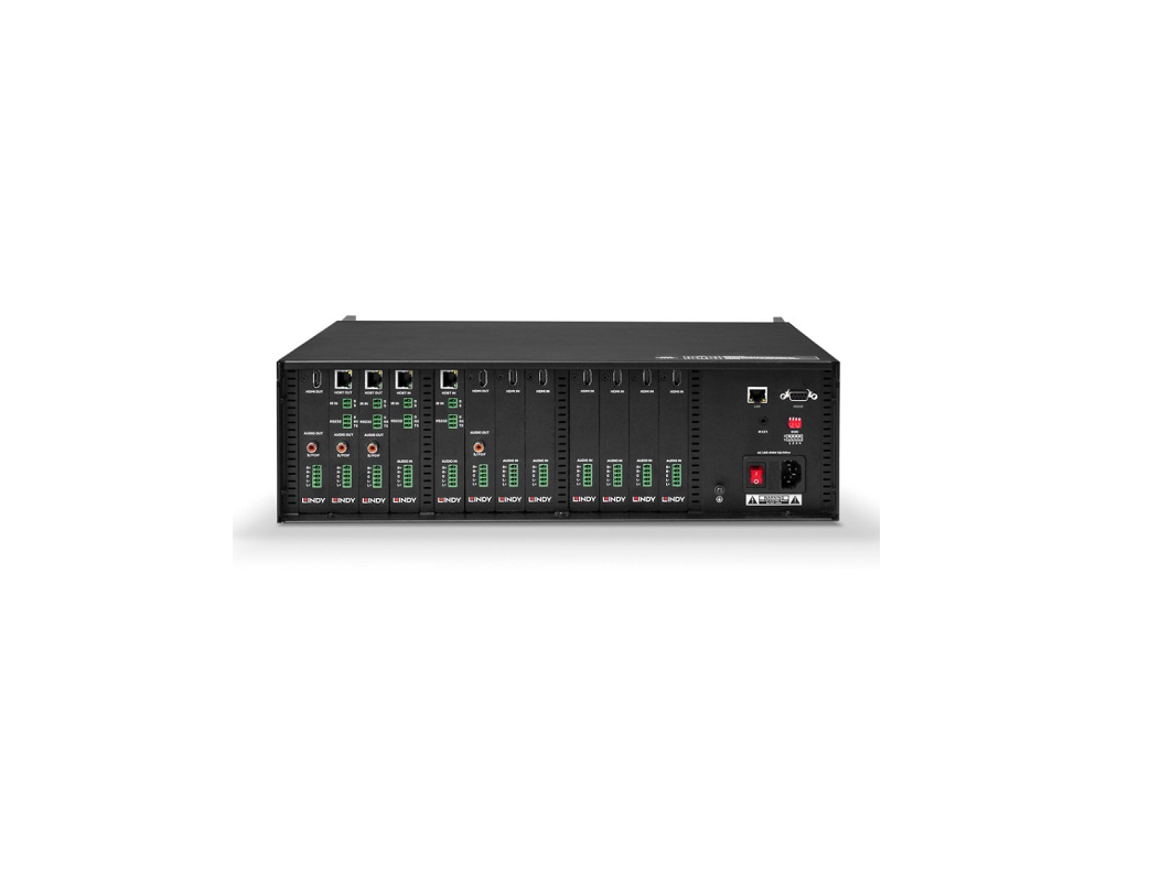
Thank you for purchasing the 12 Slot Seamless Modular Matrix and supporting AV boards. This product has been designed to provide trouble free, reliable operation. It benefits from both a LINDY 2-year warranty and free lifetime technical support. To ensure correct use, please read this manual carefully and retain it for future reference. The Lindy 12 Slot Seamless Modular Matrix is a powerful AV device that creates flexible, centralised installations in a variety of environments. With fully customisable configurations of HDMI and HDBaseT boards possible, from 1×11, 6×6, 8×4 and more, this solution can be tailored to meet the requirements of any installation within education, hospitality, corporate or government sectors.
Safety Information
! WARNING!
Please read the following safety information carefully and always keep this document with the product.Failure to follow these precautions can result in serious injuries or death from electric shock, fire or damage to the product.The device works with a high voltage of up to 230 VAC (North Americas: 120 VAC). Touching the internal components or a damaged cable may cause electric shock, which may result in death.To reduce risk of fire, electric shocks or damage:
- Do not open the product. There are no user serviceable parts inside.
- Qualified servicing personnel must only carry out any repairs or maintenance.
- Never use damaged cables.
- Do not expose the product to water or places of moisture.
- This product is intended for indoor use only.
- Do not place the product near direct heat sources. Always place it in a well-ventilated place.
- Do not place heavy items on the product or the cables.
Package Contents
38350
- Seamless Modular Matrix Chassis
- Country Specific AC Power Cord, 1.2m
- IR Extension Cable, 1.2m
- 4 x Phoenix Connectors (Male) to 3.5mm, 2 Pins
- 4 x Phoenix Connectors (Male) to 3.5mm, 3 Pins
- 12 x Phoenix Connectors (Male) to 3.5mm, 5 Pins
- 2 x 3U Mounting Brackets
- IR Remote with CR2025 Battery
- This manual
38351
- HDMI Type A (Female) Input Board 38352
- HDMI Type A (Female) Output Board 38353
- HDBaseT Input Board 38354
- HDBaseT Output Board
Features
- 12 Slots for flexible input & output configurations: 1×11, 2×10, 3×9, 4×8, 5×7, 6×6, 7×5, 8×4, 9×3, 10×2, 11×1
- In-built scaler for each output (Please see Specifications for supported resolutions)
- Instant seamless switching of signals in less than 0.1ms
- Support 18G resolutions up to 4096× 4:4:4 8bit on HDMI Input & Output boards
- Supports 10.2G resolutions up to 4096× 4:2:0 8bit on HDBaseT Inputs, 4096× 4:4:4 8bit on HDBaseT Outputs
- Transmit signals up to 100m via HDBaseT over Cat6a/7 cable, and up to 70m over Cat5e/6 cable
- Input board’s feature analogue audio embedding
- Output boards feature analogue and digital audio de-embedding
- Supports Ethernet routing to all boards
- Front panel push button, IR, RS-232 & LAN Control
- Bi-directional RS-232 & IR control over HDBaseT
- Advanced EDID Management by Web-Gui & Dipswitch
Specification
- Supported scaling video outputs:▪ 1024×▪ 1280×▪ 1280×▪ 1600×▪ 1920×▪ 1920×▪ 3840×▪ 3840×
- Supported output audio formats:▪ HDMI Audio Pass-through▪ Digital Audio up to PCM 2.0▪ Analogue Audio up to PCM 2.0
- Operating Temperature: 0°C – 45°C (32°F – 113°F)
- Storage Temperature: -20°C – 70°C (-4°F – 158°F)
- Humidity: 10 – 90% RH (non-condensing)
- Power Requirements: AC 100~240V 50/60Hz
- Power Consumption: 130.5W – 135.6W
- Mounting Rack Space Required: 3U
- Colour: Black
- Housing Material: Metal
Installation
The Lindy 12 slot modular matrix may require significant assembly depending on your chosen installation. Please ensure this is undertaken by qualified personnel, while also ensuring the appropriate safety steps are taken to avoid any static discharge. Please install all required boards prior to connection of power. If adding or removing any boards, please power the unit down and unplug as this chassis is not hot pluggable. We also advise that any terminal connections are ran and terminated in advance of connecting power. Please ensure all connected source devices, display and other equipment are powered down before making any connections.
Once the desired layout of boards is fitted please follow the guide below for installation:
- Connect an HDMI source device or HDMI equipment to the HDMI Input port of the Input board using HDMI cable.
- Connect HDBaseT transmitters to the HDBaseT input ports of the HDBaseT input boards using Cat.X cable.
- Connect an audio device to the analogue audio input ports on the input boards for audio embedding.
- Connect an HDMI display, projector or devices to the HDMI output port of the out board using HDMI cable.
- Connect HDBaseT receivers to the HDBaseT output ports of the output boards using Cat.X cable.
- Connect digital and/or analogue audio devices to the audio output ports on the output boards for audio de-embedding.
- Connect the country specific AC power cord and power on the matrix by pushing the Power button on the front chassis panel. The front panel LED will show Lindy 38350 for around 5 seconds, then show IIIIIIII0000 and 1~12 in alternate patterns in intervals of 2 seconds. The LEDs will then show the configuration of the input & output boards. The matrix is now ready for operation.
- Switch between sources and displays using the various methods of switching. For a detailed manual on these methods please see the manual on your local Lindy website.
- If using the IR extension, please connect IR receiver cable to the IR Extension port of the chassis and ensure the eye is in clear line of sight.
Please note: 1-12 is red from left to right on both the front and rear of the chassis. 1 on the front panel label will correspond with the 1st empty slot on the rear of the unit. On the LED panel, No.1 will always represent the first connected board when viewing from the left of the rear of the unit. If this board is removed, NO.1 will become the next connected board.
Installation of the mounting handles
- Remove the four screws from either side of the top panel.
- Remove the four screws from both side panels which lock the power bracket into place.
- Move the power bracket slightly to the position shown here (->). This will allow easier access when removing the ethernet connection in a later step.
- Remove the connector that is housed between the main PCB and power board. Please see here (->) for more information.

- Remove the power board bracket by tilting to one side gently.
- Remove the ethernet connection as shown here (->).
- Lock the handles at either side of the front panel using screws in the places shown here (->).
- Refit all removed parts securely.

Chassis & Board Layout
38350 – Chassis Front Panel

- Input LED Indicator – The LED screen will indicate the inserted input board status when powered on.
- Output LED Indicator – The LED screen will show the input channel number selected for each output
- IR – IR Receiver Eye
- Input & Output Select Button – Select the input & output channel. The Left & Right button can select the output. Up & Down can select the input.
- Enter Button – Press the enter button to select the specific input and output.
38350 – Chassis Rear Panel
- RJ-45 (Female) Port – LAN Connection for control systems via Web Gui & Telnet.
- RS-232 – Connect to control systems for RS-232/API control.
- IR Extension – Connect an IR receiver for IR control 4. IEC C14 (Female) – Connect to AC 100~240V 50/60Hz power.
- EDID Dipswitch – Provide manual EDID Management (See EDID management section of this manual for further information)
- Power – Press the power button to turn on or off the modular matrix
38351 – Single Port HDMI 18G Input Board
- HDMI (Female) Port – Connect a HDMI source device or HDMI equipment via HDMI cable
- Audio Embedding Terminal Block – Connect an audio device to embed audio over HDMI
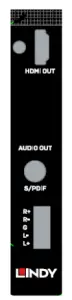
38352 – Single Port HDMI 18G Output Board
- HDMI (Female) Port – Connect a HDMI display or HDMI equipment via HDMI cable
- Audio Terminal Blocks – Connect analogue audio equipment including amplifiers or speakers for audio extraction
- SPDIF – Connect digital audio equipment including amplifiers or speakers for audio extraction
38353 – Single Port HDBaseT Input Board
- RJ-45 (Female) – Connect a HDBaseT Transmitter via Cat.x cable
- IR Terminal Blocks – Connect an IR cable for independent IR control of this board
- RS-232 Terminal Blocks – Connect an RS-232 cable for independent RS-232 control of this board 4. Audio Embedding Terminal Blocks – Connect an audio device to embed audio over HDBaseT
Control Options
Please note: many of the following settings & images are based on an example of 8 Inputs and 4 Outputs, however this will change to match your chosen configuration
Front Panel Control The chassis’ front panel can provide simple manual push button control. Please follow the steps below for controlling via this method. The LEDs will indicate the connected inputs or outputs.
- Press the Left or Right push buttons to select the connected output device, and press enter to select a connection. Once complete the corresponding LED of the output will blink slowly. When an output is switched off the LED will display “—”
- Press the Up or Down buttons to select the connected input channel. Press enter to confirm your selection, once this has been confirmed the LED will stop blinking
IR Control
The included IR Extension cable can provide simple IR control over the entire installation. Please ensure the IR eye is in clear line of sight of the included remote.Each individual HDBaseT board can also be controlled and integrated into the users control systems via IR by creating the Terminal block IR cable using the following instructions and Pin Out.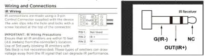
Web-Gui Control
The seamless modular matrix provides an intelligent Web-Gui for changing settings and control of the installation. The Web-Gui software can be accessed via the Lindy website under Downloads. To access the Web-Gui
- Connect the matrix to a LAN switch or PC using a Cat.x cable to the LAN port of the chassis.
- Type the following IP address into your web browser: 192.168.10.254Please note: the LAN switch or PC must use the IP address within the same IP segment as the matrixPlease ensure the web browser being used is the latest version
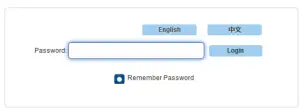
- Once the logic screen appears, please choose English. The default IP address 192.168.10.254, Subnet mask is 255.255.0.0, the default password is admin.
- The main Web-Gui screen should now appear with 2 submenus: Matrix Control & Admin Setting.
Using the Web-Gui
The Matrix Control submenu will have its own options as followed:
- Switch
- Pre-set
Switch
This option allows for the user to manage the configuration of the connected displays and source devices.
Using this layout, the user can create specific combinations of source devices and displays.Firstly, click the white button of the input or output to select, this will then turn blue. This represents that the input and output are routed.All – Routes all outputs to one inputNone – Turn off the outputs
Pre-set
Specific Input & Output configurations can be saved as pre-sets and stored on the matrix for future use.Save – Save the selected configuration of the Switch submenu. To save, press the window in the upper right corner Load – Load a pre-set configuration.
Admin Settings
The default password for the Admin Settings is 123456The admin setting submenu allows the user to perform and control the following
- CEC Setting
- Resolution Setting
- Audio Input Settings
- Port Naming
- Pre-set Naming
- Network
- Change Password
- Update Web-Gui
- Log
- Customise the Web-Gui Logo
- Reset all settings to Default
- Firmware Settings
CEC Setting
Select the Output drop down menu to the select the output to control.Select Display On to send a CEC command to power on the selected displaySelect Display Off to send a CEC command to power off the selected displaySelect Auto CEC Control to create a set automatic power off time for the display (1-30Minutes)Select Off to switch off the Auto CEC Control functionPlease note: this function is only available for displays and output devices that support CEC control
EDID Setting
The EDID settings allow the user to access and configure the EDID of each input connection
Please select enter to access these settings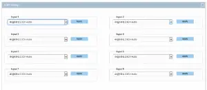
Using the drop-down menus, the EDID settings can be changed. Select Apply to set the chosen EDID.
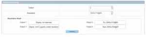
Resolution Setting
This setting allows the user to set the output resolution.Within Resolution Read, select refresh to view the current resolutions of the outputs. Using the drop-down menu, the user can select the desired output resolution.
Audio Input Setting
This setting allows the user to control which audio is embedding via the input. Using the drop-down menu, the user can select audio pass-through via the input connection or Audio In via the audio port.
Port Naming
This setting allows the user to customise the naming of both inputs and outputs.Once amended, select Save to save any changes, or Reset to reset the names to their factory naming i.e. Input 1
Please note: The naming for each port can exceed 15 characters.
Pre-set Naming
This setting allows the user to customise the naming of the saved pre-set configurationsOnce amended, select Save to save any changes, or Reset to cancel the previous change. Reset All will cancel all changes.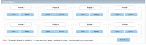
Please note: The naming for each port can exceed 15 characters
Network
This matrix can be controlled via Lan through Telnet. The default IP address for matrix access is 192.168.10.254.Select DHCP to allow the unit to automatically detect the IP address.
Select Apply to save any changes.
Please note: The Matrixes’ LAN module will auto reboot after changing the Network settings. Set Static IP:Please note: the IP address and gateway should be set up on the same segment of the networkIf an IP address is not automatically detected, select Static to manually input the IP functions. Enter the IP address ensuring it is in the same subnet segment and the PC.
Select Apply to save any changes.Please note: The Matrixes’ LAN module will auto reboot after changing the Network settings.Set Static IP:
Change Password
This setting allows the user to modify the Login Password and Admin Setting password/
The default Login password is admin. The default Admin Setting password is 123456.Select Save to save any changes.Please note: any new password must be between 4-16 characters in alphanumeric characters only.Please note: If the password has been forgotten, please use the Web-Gui or API command to reset the matrix to factory settings.This can be done by running the Web-Gui tool, highlighting and selecting the matrix. The select device from the side panel and click factory default. Select Y in the pop window to restore the matrix to factory default settings.
Update Web-Gui
This setting allows the user to update the Web-Gui
Select Update. This will take around 2 minutes to update.
Please note: the matrix will update and reboot automatically. Please wait around 3 minutes then refresh and log in again to the settings. Please do not power off the matrix while updating.
Log
This setting allows the user to hide or show the log on the bottom of the page
Custom Web-Gui Logo
This setting allows the user to customise the Web-Gui logo to suit their setup or brand. Select Browse to search for a logo file.Please note: The uploaded image must be in a PNG format with a resolution of 512x62p.Select Apply. This will trigger a pop-up window. Please select “here”. The logo will then be set to the upper left corner.
Reset All Settings to Default
Firmware
This setting allows the user to check the firmware version.
RS-232/API Control
Please follow the general setup rules for RS-232 control
- Command strings typically are not case-sensitive
- All command strings must end with the Take command “T” which will tell the system to execute the command.
- “O” is the letter O, not the number zero (0)
- Entering “X” at any point in a command string cancels the command.
- A command cannot be cancelled after the “T” has been entered.
- Command strings cannot be edited. If a mistake has been made, enter an “X” and then re-enter the command.
- To specify multiple outputs, inputs, levels, or local pre-sets, enter a space “” between each number. Multiple inputs are only valid in Disconnect commands.
- To specify a range of outputs, inputs, or local pre-sets, insert a colon “:” between the lowest and highest numbers of the range (not supported if the command is otherwise invalid, e.g., cannot specify a range of inputs in a Change command; the first input only would be routed.).
- Colons “:” and spaces “” can be used in the same command string.
- If the level designation “L” is omitted, the command is executed on the default level, which is normally Level 0.”
Default RS-232 Settings
| The default setting for RS232 port are: | |
| Parameters | Value |
| Baud Rate | 9600 bps |
| Data bits | 8 bits |
| Parity | None |
| Stop bits | 1 bit |
| Flow control | None |
Command Instructions
SET SW In Out (CR/LF):
- [SET SW] are command key words where Lindy recommend using capital letters.
- [in out] is the parameter. We would recommend using lower case letters.
- ‘\r\n’ or ‘\r’ or ‘\n’ to finish the command is acceptable.
- Use spaces where needed. ※ is a space.
- Fixed parameter. SET SW in out[CR/LF]. Only 2 parameters can be accepted.
User Manual
| Function | Command | Example |
| Switch Input for Output | Syntax
Command: SET SW in out[CR/LF]
Return: SW in out[CR/LF]
Parameter: ※ in = {in0-in11}; in0表示禁止输出 ※ out = {out1-out11,all};
Description: ※ SW is short for Switch ※ Switch one input source for one output sink |
Example Command:
SET SW in1 out1[CR/LF]
Return: SW in1 out1[CR/LF]
Description: Switch in1 for out1 |
| Show the current Input to Output layout | Syntax
Command: GET MP out[CR/LF]
Return: Mp in out[CR/LF]
Parameter: ※in = {in0-in11}; ※out = {out1-out11,all};
Description: ※MP is short for mapping ※Get which input mapping to the indicate Output |
Example Command:
GET MP out1[CR/LF]
Return: MP in1 out1[CR/LF]
Description: in1 mapping to out1 |
| To execute an audio input selection | Syntax
Command: SET AUDIOIN in prm[CR/LF]
Return: AUDIOIN in prm[CR/LF]
Parameter: ※ in = {in1-in11}; ※ prm = {hdmi/hdbt, audioin};
Description: |
Example Command:
SET AUDIOIN in1 hdmi/hdbt[CR/LF]
Return: AUDIOIN in1 hdmi/hdbt[CR/LF]
Description: Select the audio from HDMI input for input1 |
| To show output resolution | Syntax
Command: GET VIDOUT_RES out[CR/LF]
Return: VIDOUT_RES out prm[CR/LF]
Description: ※ out = {out1~out4,all} ※ prm= {101~108} {NULL: Display not detected 0: Display don’t support current selected resolution 1 : Fix 3840× 2 : Fix 3840× … … 7 : Fix 1280× 8 : Fix 1024× 101 : Auto 3840× … … 108 : Auto 1024×} |
Example Command:
GET VIDOUT_RES out1[CR/LF]
Return: VIDOUT_RES out1 1[CR/LF]
Description: out1 resolution is Fix 3840× |
| To execute a sink power by CEC | Syntax
Command: SET CEC_PWR out prm[CR/LF]
Return: CEC_PWR out prm[CR/LF]
Parameter: ※ out = {out1~out11,all}; ※ prm = {on,off}
Description: Set sink power on or off |
Example Command:
SET CEC_PWR out1 on[CR/LF]
Return: CEC_PWR out1 on[CR/LF]
Description: Set sink power on |
| Set CEC auto power on / off | Syntax
Command: SET AUTOCEC_FN out prm[CR/LF]
Return: AUTOCEC_FN out prm[CR/LF]
Parameter: ※ out = {out1~out11,all}; ※ prm = {on,off}
Description: Set sink auto power Function ON or OFF |
Example Command:
SET AUTOCEC_FN out1 on[CR/LF]
Return: AUTOCEC_FN out1 on[CR/LF]
Description: Set sink auto power ON |
| Get CEC Auto Power On/Off Status | Syntax
Command: GET AUTOCEC_FN out[CR/LF]
Return: AUTOCEC_FN out prm[CR/LF]
Parameter: ※ out = {out1~out11,all}; ※ prm = {on,off}
Description: Get Sink auto power Function ON or OFF Status. |
Example Command:
GET AUTOCEC_FN out1[CR/LF]
Return: AUTOCEC_FN out1 on[CR/LF]
Description: Get Sink auto power status,and the status is ON. |
| Set CEC Power Delay Time | Syntax
Command: SET AUTOCEC_D out prm[CR/LF]
Return: AUTOCEC_D out prm[CR/LF]
Parameter: ※ out = {out1~out11,all}; ※ prm = {1,2,3…,}// according to the actual time counter,1 means 1 minute ,2 means 2 minutes, Default wait time is 2 minutes, Max wait time is 30 minutes.
Description: AUTOCEC_D is short for CEC auto Power Delay Timing |
Example Command:
SET AUTOCEC_D out1 2[CR/LF]
Return: AUTOCEC_D iout1 2[CR/LF]
Description: when no active signal to out1, 2 minutes later, the unit will auto power off. |
| Get CEC Power Delay Time Status | Syntax
Command: GET AUTOCEC_D out[CR/LF]
Return: AUTOCEC_D out prm[CR/LF]
Parameter: ※ out = {out1~out11,all}; ※ prm = {1,2,3…,}// according to the actual time counter,1 means 1 minute ,2 means 2 minutes, Default wait time is 2 minutes,Max wait time is 30 minutes.
Description: AUTOCEC_D is short for CEC auto Power Delay Timing |
Example Command:
GET AUTOCEC_D out1[CR/LF]
Return: AUTOCEC_D out1 2[CR/LF]
Description: Get out1 auto power delay time, the result is 2 minutes |
| Get EDID
DIP status |
Syntax
Command: GET EDID_DIP[CR/LF]
Return: EDID_DIP prm[CR/LF]
Parameter: ※ prm= {0~15} 0 : EDID controlled by Web UI and API 1 : 4:4:4 8bit 2.0ch audio Without HDR 2 : 4:4:4 8bit 2.0ch audio Without HDR 3 : 4:4:4 8bit 2.0ch audio Without HDR 4…15 : Customize,
Description: Get EDID DIP status |
Example Command:
GET EDID_DIP[CR/LF]
Return: EDID_DIP 0[CR/LF]
Description: |
| Set Input EDID | Syntax
Command: SET EDID in prm[CR/LF]
Return: EDID in prm[CR/LF]
Parameter: ※ in = {in1-in11}; // all means all inputs ※ prm = {1 ~ 3} 参数描述: { 1 : 4:4:4 8bit 2.0ch audio Without HDR 2 : 4:4:4 8bit 2.0ch audio Without HDR 3 : 4:4:4 8bit 2.0ch audio Without HDR
} Description: Set Input EDID |
Example Command:
SET EDID in1 2[CR/LF]
Return: EDID in1 2[CR/LF]
Description: Set in1 EDID fix 4:4:4 8bit 2.0ch audio Without HDR |
| Get All Input EDID status | Syntax
Command: GET EDID in [CR/LF]
Return: EDID in prm[CR] EDID in prm[CR]… EDID in prm[CR/LF]
Parameter: ※ in = {in1-in11,all}; ※ prm = {1 ~ 3} 参数描述: { 1 : 4:4:4 8bit 2.0ch audio Without |
Example Command:
GET EDID in1[CR/LF]
Return: EDID in1 1[CR/LF]
Description: Get in1 EDID Status, the result is fix 4:4:4 8bit 2.0ch audio Without HDR |
| HDR
2 : 4:4:4 8bit 2.0ch audio Without HDR 3 : 4:4:4 8bit 2.0ch audio Without HDR
}
Description: Get all input EDID Status |
||
| Factory Reset | Syntax
Command: RESET[CR/LF]
Return: RESET[CR/LF]
Parameter:
Description: Factory reset |
Example Command: RESET[CR/LF]
Return: RESET [CR/LF]
Description: Factory reset all board |
| System Reboot | Syntax
Command: REBOOT prm [CR/LF]
Return: REBOOT prm[CR/LF]
Parameter: ※ prm = {all,mainboard, ledboard, card1, card2…..card12}
Description: system reboot |
Example Command: REBOOT all [CR/LF]
Return: REBOOT all [CR/LF]
Description: System reboot |
| Get IP address | Syntax
Command: GET IPADDR [CR/LF]
Return: XXX.XXX.XXX.XXX[CR/LF]
Parameter:
Description: get ipaddr |
Example Command:
GET IPADDR [CR/LF]
Return: XXX.XXX.XXX.XXX[CR/LF]
Description: get ipaddr |
| Get selected target firmware version | Syntax
Command: GET VER target [CR/LF]
Return: VER target prm[CR/LF]
Parameter: ※ target={all,mainboard, ledboard, card1, card2…..card12} ※ prm = {…}// according to actual firmware version
Description: Get selected target firmware version |
Example Command:
GET VER all [CR/LF]
Return: VER mainboard 1.2[CR] VER ledboard 1.3[CR] VER card 1.4[CR/LF]
Description: Get all module firmware version |
| Set the System Code of the remote control | Syntax
Command: SET IR_SYSCODE prm1[CR/LF]
Return: IR_SYSCODE prm1[CR/LF]
Parameter: ※ prm1 = {all, 00,4e}; // all –means support all the system codes of the remote(0x00, 0x4e); 00 — means only support the system cose is 00 4e — means only support the system cose is 4e
Description: Set IR system code |
Example Command:
SET IR_SYSCODE 00[CR/LF]
Return: IR_SYSCODE 00[CR/LF]
Description: Set IR system code is 0x00. |
| Get the System Code of the remote control | Syntax
Command: GET IR_SYSCODE[CR/LF]
Return: IR_SYSCODE prm1[CR/LF]
Parameter: ※ prm1 = {all, 00,4e}; // all –means support all the system codes of the remote(0x00, 0x4e); 00 — means only support the system cose is 00 4e — means only support the system cose is 4e
Description: Get IR system code |
Example Command:
GET IR_SYSCODE [CR/LF]
Return: IR_SYSCODE 00 [CR/LF]
Description: IR system code is 0x00. |
| Save Preset video matrix | Syntax
Command: SAVE PRESET prm[CR/LF]
Return: PRESET_V prm[CR/LF]
Parameter: prm = {1~8}//
Description: Save Preset video matrix |
Example Command:
SAVE PRESET 1[CR/LF]
Return: PRESET 1 [CR/LF]
Description: |
| Restore Preset video matrix | Syntax
Command: RESTORE PRESET prm[CR/LF]
Return: PRESET prm[CR/LF]
Parameter: prm = {1~8}//
Description: Restore Preset Scene |
Example Command:
RESTORE PRESET 1[CR/LF]
Return: PRESET 1[CR/LF]
Description: |
EDID Management
The matrix features both Web-Gui and Dipswitch EDID management for ensuring maximum compatibility within an installation.Please note: the dipswitch has a default of 0000 with all triggers in the upward position as below
Please see below for the dipswitch EDID configurations
| DIP | HDMI In | HDBaseT In | |||
| 0 | 0 | 0 | 0 | EDID Controlled by Web-Gui & API | |
| 0 | 0 | 0 | 1 | 4:4:4 8bit 2.0CH Audio w/o HDR | 4:4:4 8bit 2.0 CH Audio w/o
HDR |
| 0 | 0 | 1 | 0 | 4:4:4 8bit 2.0CH Audio w/o HDR | 4:4:4 8bit 2.0 CH Audio w/o
HDR |
| 0 | 0 | 1 | 1 | 4:4:4 8bit 2.0 CH Audio w/o HDR | |
| 0 | 1 | 0 | 0 | 4:4:4 8bit 2.0 CH Audio w/o HDR | |
| 0 | 1 | 0 | 1 | 1920× 4:4:4 8bit 2.0CH w/o HDR | |
| 0 | 1 | 1 | 0 | 1920× 4:4:4 8bit 2.0CH w/o HDR | |
| Others | Reserved |
Please note:
- When using the EDID Dipswitch on the chassis rear panel, this will set the same EDID for all Inputs.
- When using the EDID Management of the Web-Gui and API, the EDID can be independently changed for each input.
- The EDID setting will be effective immediately.
CE/FCC Statement
CE Certification
LINDY declares that this equipment complies with relevant European CE requirements.
CE Konformitätserklärung
LINDY erklärt, dass dieses Equipment den europäischen CE-Anforderungen entspricht
UKCA Certification
LINDY declares that this equipment complies with relevant UKCA requirements.
FCC Certification
This equipment has been tested and found to comply with the limits for a Class B digital device, pursuant to part 15 of the FCC Rules. These limits are designed to provide reasonable protection against harmful interference in a residential installation.You are cautioned that changes or modification not expressly approved by the party responsible for compliance could void your authority to operate the equipment.This device complies with part 15 of the FCC Rules. Operation is subject to the following two conditions:
- This device may not cause harmful interference, and
- This device must accept any interference received, including interference that may cause undesired operation.
The enclosed power supply has passed Safety test requirements, conforming to the US American versions of the international Standard IEC 60950-1 or 60065 or 62368-1.
LINDY Herstellergarantie – Hinweis für Kunden in Deutschland
LINDY gewährt für dieses Produkt über die gesetzliche Regelung in Deutschland hinaus eine zweijährige Herstellergarantie ab Kaufdatum. Die detaillierten Bedingungen dieser Garantie finden Sie auf der LINDY Website aufgelistet bei den AGBs.
Hersteller / Manufacturer (EU): Manufacturer (UK):LINDY-Elektronik GmbH LINDY Electronics LtdMarkircher Str. 20 Sadler Forster Way68229 Mannheim Stockton-on-Tees, TS17 9JYGermany EnglandEmail: [email protected] , T: +49 (0)621 470050 [email protected], T: +44 (0)1642 754000
Recycling Information
WEEE (Waste of Electrical and Electronic Equipment), Recycling of Electronic Products
report this adEurope, United KingdomIn 2006 the European Union introduced regulations (WEEE) for the collection and recycling of all waste electrical and electronic equipment. It is no longer allowable to simply throw away electrical and electronic equipment. Instead, these products must enter the recycling process.Each individual EU member state has implemented the WEEE regulations into national law in slightly different ways. Please follow your national law when you want to dispose of any electrical or electronic products. More details can be obtained from your national WEEE recycling agency.Battery Remark:Do not put empty batteries in your domestic waste bin as they will not be recycled. Empty batteries can be returned for recycling at our trade counter or at your local household recycling centre.The raw materials enclosed in batteries such as Zinc, Iron and Nickel can be reused to a very large proportion. The recycling of batteries and disused/obsolete electronic equipment is one of the most efficient environment protection actions you can easily take.
Read More About This Manual & Download PDF:
References
[xyz-ips snippet=”download-snippet”]