
LINDY 38144 50m Cat.6 HDMI and IR Extender with PoC and Loop Out User Manual![]()
Safety Instructions
WARNING !Please read the following safety information carefully and always keep this document with the product.Failure to follow these precautions can result in serious injuries or death from electric shock, fire or damage to the product.Touching the internal components or a damaged cable may cause electric shock, which may result in death.This device is a switching type power supply and can work with supply voltages in the range 100 – 240 VAC For worldwide usability four different AC adapters are enclosed: Euro type, UK type, US/Japan type and Australia/New Zealand type. Use the appropriate AC adapter as shown in the picture and ensure it is firmly secured in place and does not detach by pulling before installing into a power socket.To reduce risk of fire, electric shocks or damage:
- Do not open the product nor its power supply. There are no user serviceable parts inside.
- Only qualified servicing personnel may carry out any repairs or maintenance.
- Never use damaged cables.
- Do not expose the product to water or places of moisture.
- Do not use this product outdoors it is intended for indoor use only.
- Do not place the product near direct heat sources. Always place it in a well-ventilated place.
- Do not place heavy items on the product or the cables.
- Please ensure any adapters are firmly secured and locked in place before inserting into a wall socket
Instructions for Use of Power Supply
Push the button and rotate anticlockwise to unlock and remove the adapter. To attach, push and rotate clockwise until the adapter is locked into place.
Introduction
Thank you for purchasing the HDMI & IR Cat.6 Extender. This product has been designed to provide trouble free, reliable operation. It benefits from both a LINDY 2-year warranty and free lifetime technical support. To ensure correct use, please read this manual carefully and retain it for future reference. The HDMI & IR Cat.6 Extender is a simple to use plug and play solution which lets you extend an HDMI AV signal up to 50m* using a single low-cost Cat.6 UUTP cable (not included). For added convenience IR signals (20-60 kHz) can also be extended using the supplied IR Receiver and Emitter cables. Supporting resolutions up to Full HD 1080p, including 1080p 3D, the Extender is designed for use in AV and digital signage applications in a variety of settings such as home, education, business, retail and healthcare. The Extender features an HDMI loop-through output on the Transmitter with simultaneous viewing so that a local display can be connected for monitoring or to create an additional viewing zone. To ensure the maximum compatibility when two displays are connected the EDID data, which determines the supported video and audio formats, can be used from either a local monitor connected to the Transmitter or the remote monitor connected to the Receiver. Power over Cat.6 (PoC) functionality enables the Extender to operate from a single power supply connected to the Transmitter, allowing the Receiver to be located where there is limited access to mains power sockets making it ideal for retro fit installations. In addition to PoC functionality the Extenders slim design and integrated mounting brackets make it easier to install in limited spaces behind modern flat screen displays. *Please Note: The quoted lengths and resolutions are possible with a direct connection between Transmitter and Receiver using good quality Cat.6 solid core cable. Using a different cable type, or introducing wall plates, couplers or patch panels will result in a reduction of possible distances.
Package Contents
- HDMI & IR Cat.6 Extender with local HDMI Output
- 5V DC 1A Multi-Country Power Supply (UK, EU, US & AUS), Barrel Size: 5.5/2.1mm
- IR Emitter Cable, 1m
- IR Receiver Cable, 1m
- Lindy Manual
Specification
- Extends HDMI (including HDCP) & IR signals via Cat5e/Cat6 UTP Cable
- Connection is via cat.5e/6/7 cable, up to 50m (CAT6 solid core recommended)
- Local HDMI Output allows local & remote displays to be used simultaneously
- Supports resolutions up to Full HD 1080p 60Hz (4:4:4 @ 8bpc / 4:2:2 @ 12bpc ) at 50m
- Supports Full HD 1080p24 3D according to HDMI 1.4
- Audio Formats: LPCM, DTS Digital, DTS HD, Dolby Digital & Dolby True HD
- PoC (Power over CAT6) feature allows requires only a 5V 1A PSU to be attached
- Supports 20 – 60kHz IR Frequencies
- Maximum HDMI Cable length, 3m in/out
- EDID can be selected from either the remote or local display
- Transmitter ports: HDMI Type A In, 1x CATX Out, 3.5mm IR Out & DC Socket
- Receiver ports: HDMI Type A Out, 1x CATX In & 3.5mm IR In
- Power consumption: 5W Max
- ESD Protection: Human Body model: +/- 8kV (air-gap discharge) +/- 4kV (contact discharge)
- Temperature: Operating: 0oC to 40oC (32oF to 104oF) / Storage: -20oC to 60oC (-4oF to 140oF)
- Relative Humidity: 20 to 90% RH (Non-condensing)
Overview
Transmitter Unit
- HDMI In – Connect to an HDMI source device, such as Media Player or Blu-ray player.
- EDID Switch – Locate the switch to the right to copy the EDID information from the display connected to the HDMI Out port of the Transmitter or to the left to copy the EDID information from the display connected to the Receiver.
- HDMI Out – Connect to an HDMI display to for local monitoring or to create an additional viewing zone.
- IR Out – Connect the supplied IR Emitter cable and place the other end of the cable in line of sight of the IR port of the device to be controlled.
- Power LED – Illuminates when the Transmitter unit is receiving power.
- CAT – Connect a Cat.5e/6 cable of up to 50m to this port and the corresponding port on the Receiver.
- LINK LED – Illuminates when the Transmitter is receiving a signal from the HDMI source.
- DC5V – Connect the supplied 5V power supply to power the Transmitter and Receiver units.
Receiver Unit
- EQ – Set the EQ dip switches to the corresponding setting for the length of Cat.5e/6 cable you are using. Please refer to the Installation section for further information.
- HDMI Out – Connect to an HDMI display or projector.
- IR IN – Connect the supplied IR Receiver cable and place the other end of the cable in a location where it is in line of sight of the IR remote control to be used.
- Power LED – Illuminates when the Receiver unit is receiving power from the Transmitter via the PoC feature.
- CAT – Connect a Cat.5e/6 cable of up to 50m to this port and the corresponding port on the Transmitter.
- Lock LED – Illuminates when a stable HDMI signal is being received from the Transmitter.
Installation
Important! If you want to lay cables inside a cable duct or through a wall, please test your Cat.5e/6 cables in a test installation at the highest desired resolution/colour space/colour depth combination with the extender BEFORE you install them in your wall or cable duct!The following steps are for an installation using HDMI equipment, if you are using DVI equipment, please substitute the HDMI cables for DVI to HDMI cables where required.
- Connect your HDMI source to the Transmitter unit using a HDMI cable (maximum length 3m).
- Connect one end of the CAT5e/6 cable (max. length 50m) to the CAT port on the Transmitter and the other end to the CAT port of the Receiver. Use solid core installation cable of at least Cat.5e UTP.
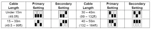
- Set the EQ on the Receiver to the setting which matches the Cat.5e/6 cable length (see table below), either the Primary or Secondary may be used depending on picture and cable quality.

- Use another HDMI cable (maximum length 3m) to connect your HDMI display device to the HDMI output port on the Receiver unit.
- An additional HDMI display can be connected to the HDMI Out port of the Transmitter if required.
- Set the EDID Switch according to your requirement, to the right uses the EDID from the display connected to the Transmitter, to the left uses the EDID from the display connected to the Receiver.
- For additional Infrared remote signal functionality, connect the included IR Extension Cables to the Transmitter and Receiver units, using the IR Emitter with the IR Out port and the IR Receiver with the IR In port.
- Place the IR Emitter in front of the IR Port of the equipment you want to control, and ensure you place the IR Receiver in a location where it may easily receive the signal of your IR remote.
- Power on your HDMI Source and Display to complete the installation.
- Finally plug the DC power supply into the Transmitter unit, the Power LED will illuminate on both units.
Troubleshooting
 report this ad
There is no display on the screen.
- Check that the DC plug and jack used by external power supply is firmly connected and that the Power LED on both the Transmitter and Receiver are illuminated.
- Check that the CAT5e/6 cable is seated correctly and that the Lock LED on is illuminated.
- Power off all the devices, then power on in this order: first, the Transmitter unit, followed by the display(s) and finally the source.
- For some HDMI devices it may be helpful to unplug and replug their HDMI connection to re-initiate the HDMI handshake and recognition.
- Check that the EQ setting matches the Cat.5e/6 cable length being used. If the primary EQ setting does not work, please try the secondary setting for the length of Cat.5e/6 cable being used.
- Reduce the length of CAT5e/6 or HDMI cable used, or use a higher quality cable.
Read More About This Manual & Download PDF:
References
[xyz-ips snippet=”download-snippet”]