LINDY 4 Port HDMI 18G Switch with Audio User Manual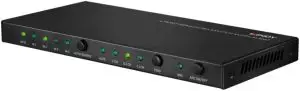
Introduction
Thank you for purchasing the Lindy 4 Port HDMI 2.0 18G Switch with Audio. This product has been designed to provide trouble free, reliable operation. It benefits from both a LINDY 2 year warranty and free lifetime technical support. To ensure correct use, please read this manual carefully and retain it for future reference.
The Lindy 4 Port HDMI 2.0 18G Switch with Audio is a professional solution for providing simple yet reliable switching control over 4 HDMI source devices connected to a single HDMI display, while also increasing a display’s available HDMI port connections.
Package Contents
- 4 Port HDMI Switch with Audio
- 5VDC 1A Multi-country Power Supply (UK, EU, US & AUS), 5.5/2.1mm
- IR Cable, approx. 1.5m (4,92ft)
- Mini Optical to Optical Adapter
- Remote Control and CR2032L Battery
- 3.5mm RS-232 Cable, approx. 1m (3.28ft)
- This Manual
Features
- Supports resolutions up 3840×, with support for High Dynamic Range
- 3.5mm Female port with Toslink (Optical) adapter for HDMI audio extraction
- IR, Push button, Auto switching and RS-232 control functions
- CEC Pass-through support
- Audio EDID Management switch
- ARC support
Specification
- HDCP 2.2/1.4 Pass-through
- Input Ports: 4 x HDMI Type A (Female), Output Ports: HDMI Type A (Female), 3.5mm (Female)
- Control Ports: RS-232 (3.5mm), IR (3.5mm)
- Audio EDID:2CH – LPCM 2CH5.1CH – LPCM 2CH, Dolby Digital 5.1, DTS 5.17.1CH – LPCM 2CH, LPCM 7.1, Doby Digital 7.1, DTS 7.1, DTS-HD 7.1, Dolby Digital 7.1
- Operating Temperature: 0°C – 40°C (32°F – 104°F)
- Storage Temperature: -20°C – 60°C (-4°F – 140°F)
- Humidity: 20-90% RH (non-condensing)
Installation
Please ensure all devices are switched off before making any connections. Using HDMI cable, connect a source device such as a games console or set top box to a HDMI switch input port, and connect the switch output port to a HDMI port of the display. Once all connections are made, please connect the power supply and turn on in the following order: display, HDMI switch, and source device.
Operation
Switch Front Panel
- Input Indicator LED: When a input port has been selected, the corresponding LED will illuminate
- Auto/Source: To select auto switching or manual switching, please hold this for more than seconds. When manual switching is activated, a short press will select the required input port.
- EDID Status LED: The selected EDID option will illuminate. The Auto LED indicates the display’s EDID is being used.
- EDID Select button: Pressing this button will switch between each of the 4 Audio EDID options: Auto/2CH/5.1CH/7.1CH
- ARC Status LED: If ARC is enabled successfully, this LED will illuminate.
- ARC On/Off: Press to turn the ARC function on or off
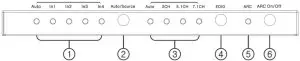
Switch Rear Panel

- HDMI Output Port: Connect with the display using HDMI cable
- HDMI Input Ports: Connect with the source devices using HDMI cable
- Audio Output Port: Connect to analogue speakers or amplifier using a 3.5mm audio cable (not included). For Toslink (Optical) connections, please use the Mini Optical to Optical adapter included.
- RS-232 Port: Control the switch using a PC and RS-232 commands, using the included 3.5mm to RS-232 cable. The RS-232 commands are below.
- IR Receiver Port: Control the switch using the included 3.5mm IR receiver cable and IR remote
- 5VDC 1A PSU Port: Connect to the included PSU.
IR Remote

- ARC: Press to enable or disable the ARC function. The ARC LED on the switch will illuminate when the function is enabled.
- Auto/2.1CH/5.1CH/7.1CH: Press to select the different EDID setting. The corresponding LED will illuminate on the switch.
- Auto/Source: Press to select auto switching or manual switching mode
- IN1/IN2/IN3/IN4: Press to select the input port. Please note, the switch must be in manual switching mode.
RS-232 Command List
The product can be controlled using the “Upper Computer” software. This is available to download at lindy.com from the 38249 Product web page.
Once the switch is connected to a PC using the included 3.5mm to RS-232 cable, open the Upper Computer software.
Please select the relevant ‘COM’ port, and set the Baud rate to 19200, then press connect.
Once connected, all software will be available to use
The commands for controlling the switch are below:
- Baud rate: 19200
- Data Width: 8bit
- Parity: None
- Stop: 1 bit
To switch the output to the required input
- Input 1: A5 5B 02 03 01 00 01 00 00 00 00 00 F9
- Input 2: A5 5B 02 03 02 00 01 00 00 00 00 00 F8
- Input 3: A5 5B 02 03 03 00 01 00 00 00 00 00 F7
- Input 4: A5 5B 02 03 04 00 01 00 00 00 00 00 F6
Query Input: A5 5B 02 01 01 00 00 00 00 00 00 00 FC
- Input 1: A5 5B 02 01 01 00 01 00 00 00 00 00 FB
- Input 2: A5 5B 02 01 01 00 02 00 00 00 00 00 FA
- Input 3: A5 5B 02 01 01 00 03 00 00 00 00 00 F9
- Input 4: A5 5B 02 01 01 00 04 00 00 00 00 00 F8
Audio Switch
- Audio Auto: A5 5B 03 02 01 00 01 00 00 00 00 00 F9
- Stereo Audio 2.0: A5 5B 03 02 02 00 01 00 00 00 00 00 F8
- Dolby/DTS 5.1: A5 5B 03 02 03 00 01 00 00 00 00 00 F7
- HD Audio 7.1: A5 5B 03 02 04 00 01 00 00 00 00 00 F6
Query Audio A5 5B 01 0C 01 00 00 00 00 00 00 00 F2
- Audio Auto: A5 5B 01 0C 01 00 01 00 00 00 00 00 F1
- Audio 2.0: A5 5B 01 0C 01 00 02 00 00 00 00 00 F0
- Audio 5.1: A5 5B 01 0C 01 00 03 00 00 00 00 00 EF
- Audio 7.1: A5 5B 01 0C 01 00 04 00 00 00 00 00 EE
Auto Switch
- ON: A5 5B 02 05 0F 00 00 00 00 00 00 00 EA
- OFF: A5 5B 02 05 F0 00 00 00 00 00 00 00 09
Query Auto: A5 5B 01 0D 00 00 00 00 00 00 00 00 F2
- Auto ON: A5 5B 01 0D 0F 00 00 00 00 00 00 00 E3
- Auto OFF: A5 5B 01 0D F0 00 00 00 00 00 00 00 02
ARC
- ON: A5 5B 10 01 0F 00 01 00 00 00 00 00 DF
- OFF: A5 5B 10 01 F0 00 01 00 00 00 00 00 FE
Query ARC: A5 5B 10 02 00 00 01 00 00 00 00 00 ED
- ARC ON: A5 5B 10 02 0F 00 01 00 00 00 00 00 DE
- ARC OFF: A5 5B 10 02 F0 00 01 00 00 00 00 00 FD
report this adDevice Information Query ( e.g:No Devices Connected)
- HDMI IN1: A5 5B 01 04 01 00 00 00 00 00 00 00 FA
- HDMI IN2: A5 5B 01 04 02 00 00 00 00 00 00 00 F9
- HDMI IN3: A5 5B 01 04 03 00 00 00 00 00 00 00 F8
- HDMI IN4: A5 5B 01 04 04 00 00 00 00 00 00 00 F7
- HDMI OUT: A5 5B 01 05 01 00 00 00 00 00 00 00 F9
References
[xyz-ips snippet=”download-snippet”]