![]()
PILOT’S GUIDE
40-00-0402 – Bwww.line6.com/manuals© 2018 Yamaha Guitar Group, Inc. All rights reserved.
System Overview
- Wireless freedom for your pedalboard
- Best in class sound quality provided by:
- 24-bit uncompressed digital transmission
- Best in class DAC and ADC provide super low noise transmission (better than 110dB dynamic range)
- Easy to use – no setup required
- Automatically chooses the best channel for true playing freedom
- Optional manual channel selection for setups with multiple wireless units
- Up to 8 hours of playing time per charge
- Up to 130 ft. (40 meters) wireless range
2.4GHz WirelessSince the Relay®G10S is a 2.4GHz wireless system, please avoid placing the receiver next to other RF transmitting equipment. We recommend that you install the G10S receiver at least 10 ft. (3 meters) away from RF transmitters (e.g., Wi-Fi routers).The Relay G10S system automatically selects the best channel when the transmitter is docked in the receiver and the Channel Selector is set to AUTO. After changing WiFi or other 2.4GHz wireless channels, please dock the transmitter in the receiver for at least 10 seconds.
What’s in the Box:
- Relay G10T Guitar Transmitter (not included in Relay G10SR Receiver Separate)
- Relay G10SR Receiver
- 9V DC Power Supply
- Right-angled 1/4″ Adapter (not included in Relay G10SR Receiver Separate)
- USB-A to Micro USB-B Cable
- Pilot’s Guide and End User License Agreement
Getting Started
- Plug the transmitter into the receiver. Inserting the transmitter all the way into the receiver allows the battery to charge. A green steady LED on the transmitter indicates the transmitter is fully charged. While docked, the transmitter and the receiver automatically set themselves to the best channel.

- Plug the transmitter into a guitar.
- Connect the receiver to a 9V or USB power source. Connect the receiver’s Instrument Output into an amp or FX unit.
- For use as a DI with bass and acoustic guitars connect the XLR DI Out to a mixer or audio interface.
Transmitter Details
- Battery Status – This LED illuminates green when the transmitter is powered on and while more than 30 minutes of operating time remain. The LED flashes red when less than 30 minutes of operating time remain. When the transmitter is plugged into the receiver for charging, a flashing red LED indicates less than 30 minutes of battery operation, a flashing green LED indicates more than 30 minutes of battery operation and a steady green LED indicates a fully charged transmitter.
- Guitar Plug – Plug into the guitar.
- Antenna – The calibrated internal antenna avoids damage or deformity in normal use. Avoid covering the antenna area with metallic fabrics or accessories, and avoid direct contact with parts of the performer’s body for best results.
Sleep Mode – To extend battery life, sleep mode is activated after a period of 4 minutes where no audio input is detected. The transmitter “wakes up” automatically when the instrument is played.
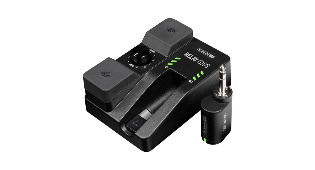
Receiver Details
![]()
- Cable Tone – When a guitar is connected to a pedal or amp with a cable, the cable alters the sound, depending on the cable’s length. Cable Tone adds a 10 ft. or 30 ft. cable emulation to the sound.
- Micro USB – Use for firmware updates and optional power.
- 9V DC Power – Use for primary DC (9VDC / 500mA) power.
- Instrument Output – Connect to the input of a guitar pedal or amplifier.
- XLR DI Output – Balanced XLR output for connection to a mixing desk, audio interface, powered speaker, or similar with DI level.
- Channel Selector – With the G10T transmitter docked in the receiver, set to AUTO for automatic channel selection. Or, with the G10T transmitter docked in the receiver, set to a channel number to select a fixedchannel. This is recommended when several wireless units are in use.
- Antennas – Diversity antennas receive the RF signal from the G10T transmitter. Please make sure that the antennas are not covered.
- RF LEDs – 3 LEDs indicate the RF signal quality in green. When selecting a manual RF channel while no G10T transmitter is currently received, these LEDs indicate interference levels in red. This helps toselect the RF channel with the least amount of interference.• 3 Red LEDs = More than 75% interference (not usable)• 2 Red LEDs = 50% interference (usable, but only for short range)• 1 Red LED = 25% interference (usable, also indicates power on)
- Battery LEDs – 3 LEDs indicate the amount of remaining battery life while the G10T is in use.• 3 Green LEDs = More than 6 hours• 2 Green LEDs = More than 3 hours• 1 Green LED = More than 1.5 hours• 1 Red LED = More than 30 minutes• 1 Flashing Red LED = Less than 30 minutes
- Release Latch – Keeps the G10T insecure transport position. To remove the G10T transmitter, push down on the latch while pulling the G10 Tout.
- G10T Transmitter, Docked – With the G10T transmitter docked, the battery is charged and the channel is set on the G10T. With the Channel Selector set to AUTO, the G10S receiver performs a scan and automatically sets the receiver and transmitter to the best available channel.
To store and transport the Relay G10S system – Pull the G10T transmitter out to the first click so that it is powered off and the battery cannot discharge.
![]()
Right-angled 1/4″ Adapter – The included Relay G10 transmitter adapter can be used to place the transmitter at a right angle into the guitar if such placement is desired. It also provides improved compatibility with active guitars that have non-standard jack wiring. Please see line6.com/support/g10adapter for more information.
![]()
© 2018 Yamaha Guitar Group, Inc. All rights reserved.Line 6, the Line 6 logo, and Relay are trademarks or registered trademarks of Yamaha Guitar Group, Inc. in the U.S. and/or other jurisdictions.SERIAL NO:
References
[xyz-ips snippet=”download-snippet”]