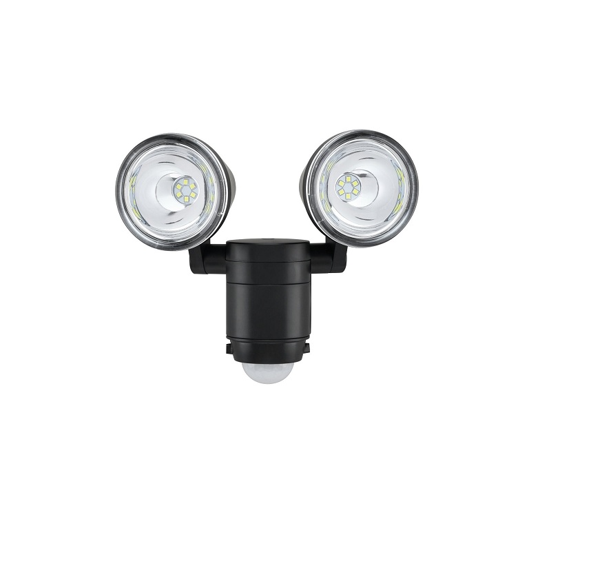
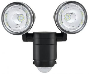
Link2Home Solar Motion Sensor Security Light Instructions
Safety Information
PRECAUTIONSPlease read and understand this entire manual before attempting to assemble, install, or operate this light fixture. This light fixture should be installed outdoors to a wall. The light fixture should be mounted approximately 7ft. (2.0m) above the ground. Do not mix old and new batteries. Do not mix alkaline, standard (carbon-zinc), or rechargeable (ni-cad, ni-mh, etc) batteries.
Pre-Installation
Planning Installation.Before installing the light fixture, ensure that all parts are present. Compare parts with the Hardware Included and Package Contents sections. If any part is missing or damaged, do not attempt to assemble, install, or operate this light fixture.Estimated installation time: 30 minutes
Specifications
| Range | Up to 27 ft. (8 m) (Varies with surrounding temperature) |
| Sensing angle | Up to 110° |
| Lumens | 700+/-10% |
| Power requirements | 2*3.7V 3600mAh 18650 Li-ion(included) |
| Operating modes | User can turn the control knob TIME/ LUX to adjust |
| Time delay | 3 seconds to 7 minutes |
TOOLS REQUIRED
- Phillips Screwdriver

- Safety goggles
- Ladder
- Drill
- Level


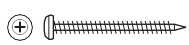
Hardware IncludedNOTE: Hardware shown to actual size.
 _____ AA
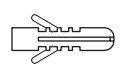 _____ BB
| Part | Description | Quantity |
| AA | Mounting screw | 6 |
| BB | Wall anchor | 6 |
Package Contents

| Part | Description | Quantity |
| A | Lamp head | 1 |
| B | Light fixture | 1 |
| C | Motion sensor | 1 |
| D | Mounting plate | 1 |
Installation
Determining the mounting locationNOTE: The light fixture should be mounted approximately 7 ft. (2.0 m) above the ground. Determine the mounting location wall mount only. Position the lamp head (A) in the general direction of the desired light coverage.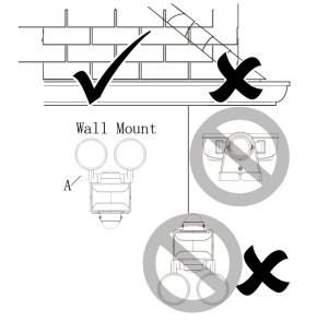
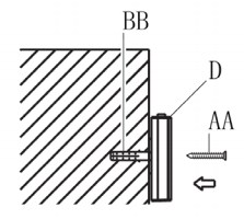
Removing the mounting plateNOTE: This fixture comes with a mounting plate (D). It is pre-assembled on the light fixture (B) for shipping. Unscrew the decorative screw (CC) in the bottom of the fixture (B), and pull the mounting plate (D) from the fixture.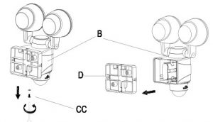 Installing the mounting platePlace the mounting plate (D) against the mounting surface and ensure the mounting plate (D) is level. Drill two holes (1) through the mounting plate (D) and into the mounting surface. If mounting to a wooden surface, install the two mounting screws (AA) through the mounting plate (D) and into the mounting surface. If mounting to wall board or brick, remove the mounting plate (D) and drill the mounting surface using the drill bit. Insert the wall anchors (BB) and attach the mounting plate (D) using the two mounting screws (AA).
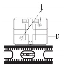
Installing the solar PanelNOTE: Ensure that the solar panel is angled so that it receives the maximum amount of sun exposure.The solar panel cable is 3m, mark and drill 4 holes in the location where you want to mount the solar panel. Use the mounting base template on the bottom of the solar panel to make your marks. Insert the wall anchors(BB) and mounting screws(AA) (included)in the holes. Place the mounting base over the holes and slide the screws through the solar panel base and into the anchors. Tighten the screws.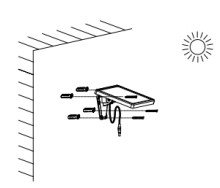
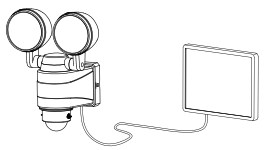
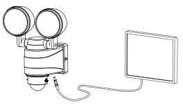
Mounting the light FixtureSlide the light fixture (B) onto the mounting plate (D), screw the decorative screw (CC) in the bottom of the fixture (D) and tighten securely.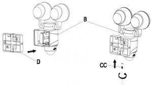 Connect the solar panel with lightNOTE: Connect the solar panel with light, exposed solar panel under sunlight for 12 hours before first use.
Operation
 Operation
Adjusting the lamp HeadIf needed, gently grasp the lamp head (A) and tilt or rotate to adjust the light coverage area.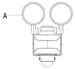
Setting the sensor for TestingNOTE: User can turn the control knob TIME to adjust the duration of the illumination from approx. 3 seconds to 7 minutes (+/-10%). User can turn the control knob LUX to adjust the daylight level at which to activate the motion detector. Adjusting the TIME controlNOTE: The “TIME” control determines the amount of time the light will stay on full bright after all motion has stopped. User can turn the control knob TIME to adjust the duration of the illumination from approx. 3 seconds to 7 minutes (+/-10%).
Adjusting the LUX controlNOTE: The “LUX” control determines how dark the surrounding light level needs to be before the motion sensor (C) will turn on the light when motion is detected. Turn the control knob LUX to adjust the daylight level: At the position![]() , the motion detector will only react at night. In the position
, the motion detector will only react at night. In the position ![]() ,the motion detector will respond at daylight levels.
,the motion detector will respond at daylight levels.
Adjusting the motion sensor detection zonePerform a “walk test”: walk in an arc across the front of the motion sensor (C). Watch the light. The light will come on indicating motion has been detected. Stop, wait for the light to turn off, and then begin walking again. Continue this process until the detection zone has been established.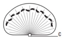
Care and Cleaning
To prolong the original appearance, clean the light fixture with clear water and a soft, damp cloth only. Do not use paints, solvents, or other chemicals on this light fixture. They could cause a premature deterioration of the finish. This is not a defect in the finish and will not be covered by the warranty. Do not spray the light fixture with a hose or power washer.
Troubleshooting
| Problem | Cause | Solution |
| The light does not switch on during nighttime | Motion detector is dirty | Clean motion detector |
| LUX control is not properly set | Turn LUX control to increase LUX level. | |
| Batteries are drained | Replace batteries | |
| The light switches on during daytime | LUX control is not properly set | Turn LUX control to decrease LUX level |
| The light does not switch | LUX control is not properly set | Turn the LUX control to the correct position. |
| Battery is not fully charged or needs replacement | exposed solar panel under sunlight for 12 hours before first use, or replacement the battery. |
LINK2HOME
1 YEAR LIMITED WARRANTYIMPORTANT: Proof of Purchase is required to obtain warranty serviceParagon Group USA Inc. warrants to the original owner that our products will be free from defect in workmanship and material for a period of ONE YEAR from the date of purchase. Should any unit(s) prove to be defective during this period, Paragon Group USA Inc. will be responsible for replacement of the defective unit(s) only. Paragon Group USA Inc. is not responsible for labor charges or any incidental or consequential expenses. Not Covered Batteries are not covered by this warranty. Repair service, adjustment and calibration due to misuse, abuse or negligence are not covered by this warranty. Unauthorized service or modification to this product or of any furnished components will void this warranty in its entirety. This warranty does not include reimbursement for inconvenience, installation, set-up time, loss of use, postage, unauthorized service, or other products used in conjunction with Link2 Home products.
For warranty service, please contactParagon Group USA Inc.Customer Service by Phone: 1-888-783-6082 ore-mail: This warranty gives you specific legal rights, and you may also have other rights which vary from state to state.Paragon Group USA Inc. Link2HomeProduct Division Englewood, NJ 07631 USA
[xyz-ips snippet=”download-snippet”]