LIPPERT Bed Slide Hydraulic In-Frame Low Profile Slide-Out
Introduction
The component’s purpose is to hydraulically actuate slide-out rooms. Its function should not be used for any purpose or reason other than to actuate the slide-out room. To use the system for any reason other than what it is designed for may result in death, serious injury or damage to the coach.
Safety Requirements
WARNING: Failure to act in accordance with the following may result in death, serious injury, coach or property damage.CAUTION: Always wear gloves while handling.Moving parts can pinch, crush or cut. Keep clear and use caution.
Note:
- Slide room is to be supported by a secondary means when servicing slide arms. Failure to do so could result in unexpected motion of the slide room.
- All slide arms are over 100 pounds in weight. Ergonomic considerations should be made for safe install.
Before actuating the system, please keep these things in mind:
- Parking locations should be clear of obstructions that may cause damage when the slide-out room is actuated.
- Be sure all persons are clear of the coach prior to the slide-out room actuation.
- Keep hands and other body parts away from slide-out mechanisms during actuation.
- To optimize slide-out actuation, park coach on solid and level ground.
Operation Instructions
Extending Slide-Out Room
- Level the coach.
- Verify the battery is fully charged and hooked up to the electrical system.
- Remove transit bars (if so equipped).
- Press and hold the IN/OUT switch (Fig. 1) in the OUT position (Fig. 1B) until room is fully extended and stops moving.
- Release switch, which will lock the room into position.Note: Only hold OUT switch until room stops.
Retracting Slide-Out Room
- Verify the battery is fully charged and hooked up to the electrical system.
- Press and hold the IN/OUT switch (Fig. 1) in the IN position (Fig. 1A) until the room is fully retracted and stops moving.
- Release the switch. This will lock the room into position.Note: Only hold IN switch until room stops.
- Install the transit bars (if so equipped).
Basic Troubleshooting
- This troubleshooting chart outlines some common problems, their causes and possible corrective actions. If any part or serial number information is available, provide it to the service technician when asking for assistance.
- Every coach has its own personality and what may work to fix one may not work on another even if the symptoms appear to be the same.
- When something restricts room travel, system performance will be unpredictable. It is very important that slide tubes be free of contamination and allowed to travel full distance (stroke). Ice or mud buildup during travel is an example of some types of contamination that can occur.
- When you begin to troubleshoot the system, make sure the battery is fully charged, there are no visible signs of external damage to the system and that all connections are secure.
- During troubleshooting, remember that if you change something, that change may affect something else. Be sure any changes you make will not create a new problem.
- You can obtain additional information on the Lippert Slide-out System by visiting www.lci1.com/customerservice or by calling 574-537-8900.
| What Is Happening? | Why? | What Should Be Done? |
| Room doesn’t move when switch is pressed. | Restriction or obstruction inside or outside of unit. | Check for and clear obstruction. |
| Low battery voltage, blown fuse, defective wiring. | Check battery voltage and charge if needed. Find and check fuse, replace if blown. Check battery terminals and wiring. Look for loose, disconnected or corroded connectors. | |
| Power unit runs but room does not move. | Restrictions both inside and outside of unit. | Check for and clear restriction. |
| Power unit runs, room moves slowly. | Low battery, poor ground, extremely low outdoor temperature. | Charge battery and check ground wire. |
| Room drifts “in” or “out.” | Possible external leak in the hydraulic system. | Tighten fittings. |
| Inspect hoses, fittings and power unit for external leaks. | ||
| Air in system. | After checking all connections, perform basic purge procedure, see Basic Purge Procedure for Hydraulic Pump Units section. | |
| In the closed position, room drifts out. | Leaking cylinder seal. | See Hydraulic Cylinder Test section. |
| Fluid bypassing cylinder piston. | See Hydraulic Cylinder Test section. | |
| Hose from pump is leaking. | Tighten fitting or replace hose. | |
| Fluid bypass in cartridge valve. | Replace cartridge valve. | |
| Loose mounting bolts. | Tighten mounting bolts. |
Basic Purge Procedure For Hydraulic Pump UnitsThe basic purge procedure to bleed the LCI Hydraulic Systems is performed without the use of any tools. The system’s own function purges the air from the hydraulic lines and cylinders by simply running the pump. These simple steps will apply to Hydraulic Landing Gear (HLG), Hydraulic Stabilizer Jacks (HSJ), Class A Motorized Vehicles Leveling Jacks (LJ) and Hydraulic Slide-outs (S/O).
- Start with all hydraulic components in the fully retracted position, meaning all jacks, landing gear stabilizers and slide-outs brought back inside the coach as if it were ready to travel.
- Find the hydraulic pump location and note the amount of fluid currently in the reservoir. The fluid level should be about ¼” from the top of the reservoir and no more than ½” from the top.NOTE: When checking the fluid level after ensuring all hydraulic components are retracted, note if there are any bubbles, froth or foam on top of the fluid. This is an indication that air has been pushed back to the reservoir when the hydraulic components were retracted in the last cycle. Wait 15-20 minutes for the foam to dissipate before beginning the purge process.
- If there is no froth or foam in the reservoir and the fluid is not within ½” of the top, fill the reservoir to within the level described in Step 2.
- With the fluid level full and no foam in the reservoir, begin cycling the hydraulic system:CLASS A – Extend LJ fully, taking the coach off the tires. If the unit has hydraulic S/O, extend all S/O. Once all LJ and S/O are extended, immediately retract all S/O and then all LJ.5TH WHEELS – Extend HLG until footpads contact the ground, extend HSJ to touch the ground, extend all S/O. Retract all S/O immediately, retract HSJ and then retract HLG.NOTE: Purging of the hydraulic system on fifth wheels should be performed with the unit coupled to the tow vehicle, a king pin stand under the pin box or jack stands under the front portion of the frame. FIFTH WHEELS WITH LEVEL-UP 6-POINT LEVELING – Fifth Wheels with the Level-Up 6-point Leveling system have the unique ability to have the HLG and LJ extend fully, resulting in the tires being lifted off the ground. These particular fifth wheels can be purged in the same fashion as the Class A units.WARNING: Do not attempt to purge this system without the front end of the fifth wheel safely supported. Doing so could result in death or serious bodily injury.
- Check the reservoir for foam. If foam is present, see NOTE above and repeat Steps 3 & 4. Repeat these steps until no foam is present in the reservoir. If no foam is present, the system is purged of air.
Hydraulic Cylinder TestHydraulic Slide-Out Cylinder – Retract Test
- Retract (close) all slide-outs (rooms) completely.
- Disconnect all rooms from system (if coach is equipped with IRC, close all but one room).
- Loosen hose from “E” (extend) port on the manifold of the Power Unit.
- Plug opening on manifold to prevent drawing air into the system.CAUTION: Do not attempt to run room out with the “E” port hose loose. The system will experience rapid fluid loss.
- Energize the Pump Unit to retract (close) room.
- When room is fully retracted, continue to run the room in and watch for fluid flow from hose/port “E.” Fluid flow greater than a few drops will indicate internal cylinder leaking (bypassing of piston seal). If greater than a few drops leak from hose fitting, piston seal is bad and will need to be replaced. If there is no fluid flow, reconnect hose to “E” port and tighten.
- Repeat steps 2 through 6 for each slide-out until all slide-outs have been tested. Energize the Pump Unit to retract (close) room.
CAUTION: Be sure to reconnect and tighten hose at the “E” port before attempting to extend (open) the room or the system will experience rapid fluid loss.
Hydraulic Slide-Out Cylinder – Extend Test
- Extend (open) all slide-outs (rooms) completely.
- Disconnect all rooms from system (if coach is equipped with IRC, open all but one room).
- Loosen hose from “R” (retract) port on the manifold of the Power Unit. Individual slide-outs can be tested if the unit is equipped with an IRC block. Close all valves in IRC except the one to be tested.CAUTION: Do not attempt to run room in with the “R” port hose loose. The system will experience rapid fluid loss.
- Plug opening on manifold to prevent drawing air into the system.
- Energize the Pump Unit to extend (open) room.
- Continue to run the room out and watch for fluid flow from hose/port “R” (or IRC block if coach is equipped with IRC). Fluid flow greater than a few drops will indicate internal cylinder leaking (bypassing of piston seal). If greater than a few drops leak from hose fitting, piston seal is bad and will need to be replaced. If there is no fluid flow, reconnect hose to “R” port and tighten.
- Repeat steps 2 through 6 for each slide-out until all slide-outs have been tested.
CAUTION:
- Be sure to reconnect and tighten hose at the “R” port before attempting to retract (close) the room or the system will experience rapid fluid loss.
- Moving parts can pinch, crush or cut. Keep clear and use caution.
NOTE: Lippert Components, Inc. recommends that the following inspections, troubleshooting, component replacement, and verifications be completed only by certified RV technicians.
WARNING:
- Always wear eye protection when performing service or maintenance to the coach. Other safety equipment to consider would be hearing protection, gloves and possibly a full face shield, depending on the nature of the service.
- The coach MUST be supported per manufacturer’s specifications before working underneath. Failure to do so may result in death or serious injury.
Adjusting the Slide Room’s Retracted Position
- Locate cylinder coming through the frame.
- Retract the room completely in.
- Check the outside T- mold and seal positioning.
- Partially extend room.
- Hold jam nut (Fig. 2A) in place with wrench.
- Adjust nylock nut (Fig. 2C) towards the bracket if the room does not seal. Adjust the nylock nut (Fig. 2C) away from the bracket if the room is too tight and damages the fascia.
NOTE: Make small adjustments, running the room in after each adjustment until proper seal is achieved.
Adjusting the Slide Room’s Extended Position
- Locate cylinder coming through the frame.
- Extend room completely out.
- Check the inside fascia and seal positioning.
- Partially retract room.
- Loosen and back off jam nut (Fig. 2A) from nut (Fig. 2B) to give nut (Fig. 2B) room for adjustment.
- Adjust nut (Fig. 2B) away from the bracket if the room extends too far and damages the inside fascia. Adjust nut (Fig. 2B) towards the bracket if the room does not seal.NOTE: Make small adjustments, running the room out after each adjustment until proper seal is achieved.
- Tighten jam nut (Fig. 2A) to nut (Fig. 2B).
Maintenance
The Lippert In-Frame Lo-Pro Slide-out System has been static tested to over 4,000 continuous cycles without any noticeable wear to rotating or sliding parts. It is recommended that when operating in harsh environments (road salt, ice build up, etc.) the moving parts be kept clean. They can be washed with mild soap and water. No grease or lubrication is necessary and in some situations may be detrimental to the environment and long term dependability of the system.
Electrical System MaintenanceFor optimum performance, the slide-out system requires full battery current and voltage. The battery MUST be maintained at full capacity. Other than good battery maintenance, check the terminals and other connections at the battery, the control switch, and the system for corrosion, and loose or damaged terminals. Check motor leads under the trailer chassis. Since these connections are subject to damage from road debris, be sure they are in good condition.
NOTE: The Lippert In-Frame Lo-Pro Slide-out System is designed to operate as a negative ground system. A negative ground system utilizes the chassis frame as a ground and an independent ground wire back to battery is necessary. It is important that the electrical components have good wire to chassis contact. To ensure the best possible ground, a star washer should be used. Over 90% of unit electrical problems are due to bad ground connections.
Mechanical MaintenanceAlthough the system is designed to be almost maintenance free, actuate the room once or twice a month to keep the seals and internal moving parts lubricated. Check for any visible signs of external damage after and before movement of the travel trailer.NOTE: For long-term storage: It is recommended that the room be closed (retracted).
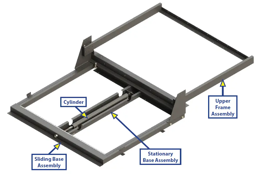
LOW PRO HYDRAULIC SLIDE ASSEMBLY
LOW PRO HYDRAULIC BED SLIDE COMPONENTS
| Callout | Part # | Description |
| A | 178058 | Stabilizer Roller Bearing Assembly |
| B | 118606 | 3/4 – 10; Hex GR5 Zinc Nut for Cylinder Mount |
| C | 129864 | 3/8 – 16 x 1; Hex Tap Bolt |
| D | 119125 | 3/8 – 16 Hex Nut |
| E | 118613 | 1/2 – 13 x 5 Hex Bolt |
| F | 118610 | 1/2 – 13; Hex Nut |
| G | 113131 | Straight Fitting |
| H | 141109 | O-Ring Face Seal Straight Fitting |
| I | 173738 | O-Ring Face Seal Elbow Fitting |
| J | 138416 | Hose Coupling |
| K | 249363 | O-Ring Hose End Fitting |
| L | 113128 | JIC to O-Ring 90 Degree Elbow Fitting |
| M | 113130 | T-Fitting with O-Ring on Run |
| N | 139417 | Long Straight Fitting |
| Callout | Part # | Description |
| O | 125653 | 24″ Hydraulic Cylinder |
| P | 248654 | Orange Hydraulic Hose |
| Q | 248653 | Black Hydraulic Hose |
The contents of this manual are proprietary and copyright protected by Lippert Components, Inc. (“LCI”). LCI prohibits the copying or dissemination of portions of this manual unless prior written consent from an authorized LCI representative has been provided. Any unauthorized use shall void any applicable warranty. The information contained in this manual is subject to change without notice and at the sole discretion of LCI. Revised editions are available for free download from lci1.com
Please recycle all obsolete materials.For all concerns or questions, please contactLippert Components, Inc.Ph: (574) 537-8900 | Web: lci1.com | Email: [email protected]
 report this ad
References
[xyz-ips snippet=”download-snippet”]