![]()
Manual StepsInstallation and Owner’s Manual(For Aftermarket Applications)
Introduction
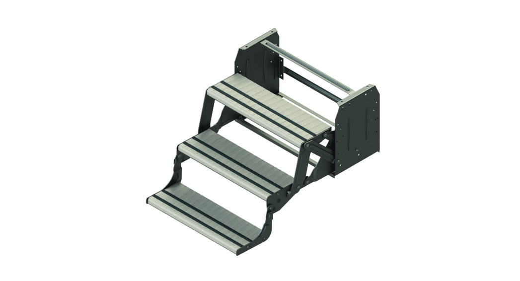
This document details the installation, operation, and maintenance of manual steps.Safety
WARNING
![]() THE “WARNING” SYMBOL ABOVE IS A SIGN THAT AN INSTALLATION PROCEDURE HAS A SAFETY RISK INVOLVED AND MAY CAUSE DEATH OR SERIOUS INJURY IF NOT PERFORMED SAFELY AND WITHIN THE PARAMETERS SET FORTH IN THIS MANUAL. ALWAYS WEAR EYE PROTECTION WHEN PERFORMING THISINSTALLATION PROCEDURE. OTHER SAFETY EQUIPMENT TO CONSIDER WOULD BE HEARING PROTECTION, GLOVES, AND POSSIBLY A FULL FACE SHIELD, DEPENDING ON THE NATURE OF THE INSTALLATION PROCEDURE.
THE “WARNING” SYMBOL ABOVE IS A SIGN THAT AN INSTALLATION PROCEDURE HAS A SAFETY RISK INVOLVED AND MAY CAUSE DEATH OR SERIOUS INJURY IF NOT PERFORMED SAFELY AND WITHIN THE PARAMETERS SET FORTH IN THIS MANUAL. ALWAYS WEAR EYE PROTECTION WHEN PERFORMING THISINSTALLATION PROCEDURE. OTHER SAFETY EQUIPMENT TO CONSIDER WOULD BE HEARING PROTECTION, GLOVES, AND POSSIBLY A FULL FACE SHIELD, DEPENDING ON THE NATURE OF THE INSTALLATION PROCEDURE.
THE TRAILER MUST BE SUPPORTED PER THE MANUFACTURER’S SPECIFICATIONS BEFORE WORKING UNDERNEATH. FAILURE TO DO SO MAY RESULT IN DEATH OR SERIOUS INJURY.
![]() CAUTIONMOVING PARTS CAN PINCH, CRUSH OR CUT. KEEP CLEAR AND USE CAUTION.
CAUTIONMOVING PARTS CAN PINCH, CRUSH OR CUT. KEEP CLEAR AND USE CAUTION.
Part Numbers
| Part # | Description |
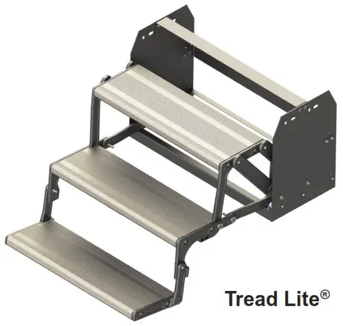
| 328730 | Tread Lite® Single Step (Replace with #430063) |
| 344420 | Tread Lite® Double Step (Obsolete) |
| 258998 | Tread Lite® Triple Step (Replace with #432696) |
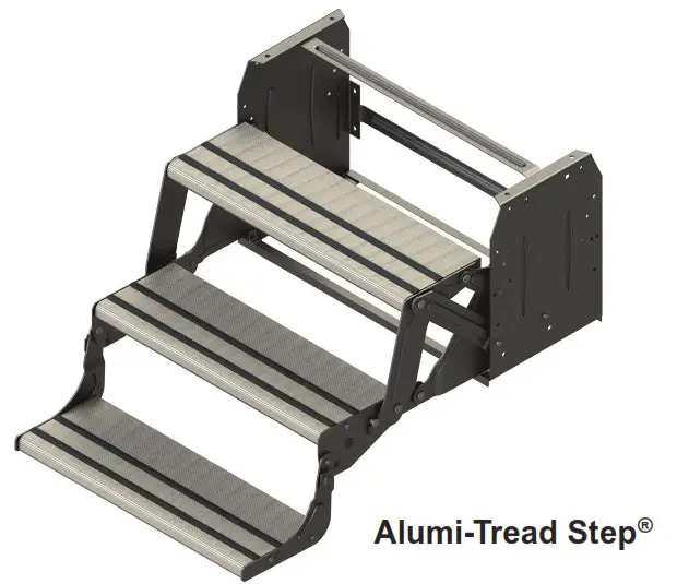
| 430063 | Alumi-Tread® Single Step |
| 429994 | Alumi-Tread® Double Step |
| 432696 | Alumi-Tread® Triple Step |
| 432698 | Alumi-Tread® Quad Step |
| 432678 | 24” Radius Single Steel Step (Formerly #341499) |
| 432682 | 24” Radius Double Steel Step (Formerly #341500) |
| 432687 | 24” Radius Triple 7” Rise Steel Step (Formerly #341501) |
| 432690 | 24” Radius Triple 9” Rise Steel Step (Formerly #341502) |
| 358991 | 24” Radius Quad 8” Rise Steel Step (Formerly #341504) |
Preparation
Resources Required
- Cordless or Electric Drill or Screw Gun
- Appropriate Drive Bits
- 9/16″ Socket
- Four 3/8″ – 16 x 1″ Bolts, Grade 2
- Four 3/8″ – 16 Flange Nuts, Grade 2
- Two Self-Tapping 1″ x 1/4″ Screws (If needed for step support brackets)
Removal
Take off the existing step by removing the lag bolts, which secure the step to the floor, and the step bolts from the outriggers.NOTE: If the existing step has a support bracket, remove the screws securing the step to the bracket.
Installation
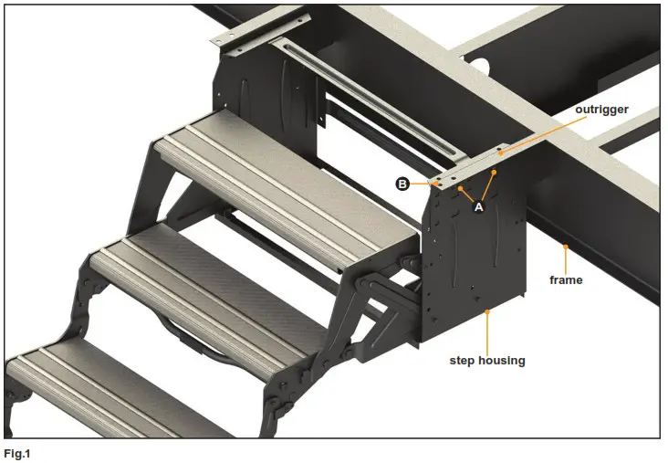
- Verify the location and squareness of the step outriggers.
- Make sure the step is completely backed up against the frame (I-beam).
NOTE: Some OEM designs allow the steps to rest against the I-beam and lag directly to the web of the beam. Other designs include step supports and, if supports are present, steps should be completely backed up against the stepsupports on the frame (angle or tube).
- Align holes in the step with holes in the outrigger (Fig.1A). Insert two bolts and flange lock nuts per side. Tighten only until snug to allow for adjustments.
- Verify that the step housing is square, level to theoutrigger, and plumb to the chassis.
- Once verified, tighten the bolts to 20 ft-lbs of torque.
NOTE: If step support brackets are located on the step, they should be secured to the chassis I-beam or stepsupport angles on the chassis by one 1″ x 1/4″ self-tapping screw per each side of the step.NOTE: The adjustable step bracket is optional and may not be included on all steps.
6. Attach lag bolt or bolts to the floor through the outer end holes in the outrigger (Fig.1B) as per the manufacturer’s recommendations.
Step Operation
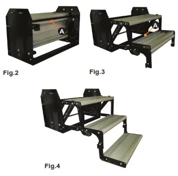
Unfolding Steps
- Pull out on the top lip of the vertically stored step (Fig.2A).
- Pull up and out on the back of the step resting on the second step (Fig.3A).
- Unfold bottom step (FIg.4).Folding Steps
- Pull up on a bottom step and fold over the second step (Fig.3A).
- Pull up on the bottom of steps and fold inward under the top step (Fig.2A).
Maintenance
Scratches
- Clear any chipped paint or material adhering to scratched area.
- Apply automotive grade primer to scratch.
- Paint primed area with automotive high gloss paint. Lubrication1. Remove all dirt and foreign matter from hinge areas.2. Lubricate hinge areas in between the sheet metal portions of the steps.
NOTE: Utilize a dry lubricant such as silicone. Wet lubricants will attract dirt and possibly cause damage to the hinge areas.
![]()
Manual information may be distributed as a complete document only unless Lippert Components provides explicit consent to distribute individual parts. All manual information is subject to change without notice. Revised editions will be available for freedownload at lci1.com. Manual information is considered factual until made obsolete by a revised version. Please recycle all obsolete materials and contact Lippert Components with concerns or questions.
lci1.com 574-537-8900CCD-0001644 Rev: 10.22.19
References
[xyz-ips snippet=”download-snippet”]