![]()
![]() Hydraulic ThroughFrame Slide-outOWNER’S MANUAL
Hydraulic ThroughFrame Slide-outOWNER’S MANUAL
Introduction
The Lippert Hydraulic Through Frame Slide-out System is intended for the sole purpose of extending and retracting the slide-out room. Its function should not be used for any other purpose or reason than to actuate the slide-out room. To use the system for any reason other than what it is designed for may result in damage to the coach and/or cause serious injury or even death.
The Lippert Hydraulic Through Frame Slide-out System is a rack-and-pinion guide system, utilizing a hydraulic cylinder to move the room assembly. The power unit drives the cylinder rod in a forward and backward motion to move the slide room in and out. The Lippert Hydraulic Slide-out System is designed to operate as a negative ground system. Before actuating the system, please keep these things in mind:
- Parking locations should be clear of obstructions that may cause damage when the slide-out room is actuated.
- Be sure all persons are clear of the coach prior to the slide-out room actuation.
- Keep hands and other body parts away from slide-out mechanisms during actuation. Severe injury or death may result.
- To optimize slide-out actuation, park coach on solid and level ground.
For information on the assembly or individual components of this product, please visit https://support.lci1.com/through-frame-selections.
NOTE: Images used in this document are for reference only when assembling, installing, and/or operating this product. The actual appearance of provided and/or purchased parts and assemblies may differ.
Safety
Read and understand all instructions before installing or operating this product. Adhere to all safety labels. This manual provides general instructions. Many variables can change the circumstances of the instructions, i.e., the degree of difficulty, operation, and ability of the individual performing the instructions. This manual cannot begin to plot out instructions for every possibility, but provides the general instructions, as necessary, for effectively interfacing with the device, product, or system. Failure to correctly follow the provided instructions may result in death, serious personal injury, severe product, and/or property damage, including voiding of the LCI limited warranty.
![]() The “WARNING” symbol above is a sign that a procedure has a safety risk involved and may cause death or serious personal injury if not performed safely and within the parameters set forth in this manual.
The “WARNING” symbol above is a sign that a procedure has a safety risk involved and may cause death or serious personal injury if not performed safely and within the parameters set forth in this manual.![]() Always wear eye protection when performing service or maintenance to the vehicle. Other safety equipment to consider would be hearing protection, gloves, and possibly a full face shield, depending on the nature of the service.
Always wear eye protection when performing service or maintenance to the vehicle. Other safety equipment to consider would be hearing protection, gloves, and possibly a full face shield, depending on the nature of the service.
![]()
Failure to act in accordance with the following may result in death, serious injury, coach, or property damage.
Prior to Operation
Prior to operating the Lippert Hydraulic Through Frame Slide-out System, follow these guidelines:
- Coach should be parked on the most level surface available.
- Leveling or stabilizing system should be actuated to ensure coach will not move during operation ofslide-out system.
- Be sure the battery is fully charged.
- Be sure to keep all persons and pets clear of the slide-out system during operation.
 Always make sure that the slide-out room path is clear of people and objects before and during the operation of the slide-out room. Always keep away from the slide rails when the room is being operated. The gear assembly may pinch or catch on loose clothing causing personal injury.NOTE: Install transit bars (if so equipped) on the slide-out room during storage and transportation.OperationExtending Slide-Out Room
 - Level the unit.
- Verify the battery is fully charged and hooked up to the electrical system.
- Remove transit bars (if so equipped).
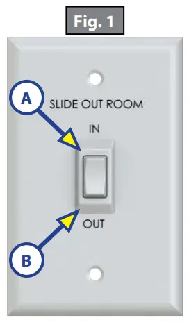
- Press and hold the IN/OUT switch (Fig.1) in the OUT position (Fig.1B) until the room is fully extended and stops moving.
- Release the switch, which will lock the room into position. NOTE: Only hold OUT switch until the room stops.
Retracting Slide-Out Room
- Verify the battery is fully charged and hooked up to the electrical system.
- Press and hold the IN/OUT switch (Fig.1) in the IN position (Fig.1A) until the room is fully retracted and stops moving.
- Release the switch. This will lock the room into position.NOTE: Only hold IN switch until the room stops.
- Install the transit bars (if so equipped).
Maintenance
InspectionAfter servicing the slide-out system in any way, be sure to check the following:
- Slide-out stops are installed and adjusted properly.
- Head assemblies are installed and adjusted properly.
- The system is mounted properly.
- Cross shafts are mounted properly and clear all other components.
- Gear packs function properly.
- Manual override is accessible.
- Outside seals compress when slide-out is retracted.
- Inside seals compress when slide-out is extended.
- Slide-out extends and retracts smoothly.
- Both sides of the slide-out are synchronized.
- Any dirt or debris is cleaned from the interior or exterior of the coach.
The Lippert Through Frame Slide-out System has been static tested to over 4,000 continuous cycles without any noticeable wear to rotating or sliding parts. It is recommended that when operating in harsh environments (road salt, ice build-up, etc.) the moving parts be kept clean. They can be washed with mild soap and water. No grease or lubrication is necessary and in some situations may be detrimental to the environment and long-term dependability of the system.
Electrical SystemFor optimum performance, the slide-out system requires full battery current and voltage. The battery must be maintained at full capacity. Other than good battery maintenance, check the terminals and other connections at the battery, the control switch, and the system for corrosion, and loose or damaged terminals. Check motor leads under the trailer chassis. Since these connections are subject to damage from road debris, be sure they are in good condition.
NOTE: The Lippert Through Frame Slide-out System is designed to operate as a negative ground system. A negative ground system utilizes the chassis frame as a ground and an independent ground wire back to the battery is necessary. It is important that the electrical components have good wire-to-chassis contact. To ensure the best possible ground, a star washer should be used. Over 90% of unit electrical problems are due to bad ground connections.
MechanicalAlthough the system is designed to be almost maintenance-free, actuate the room once or twice a month to keep the seals and internal moving parts lubricated. Check for any visible signs of external damage after and before the movement of the travel trailer.NOTE: For long-term storage: It is recommended that the room be closed (retracted).
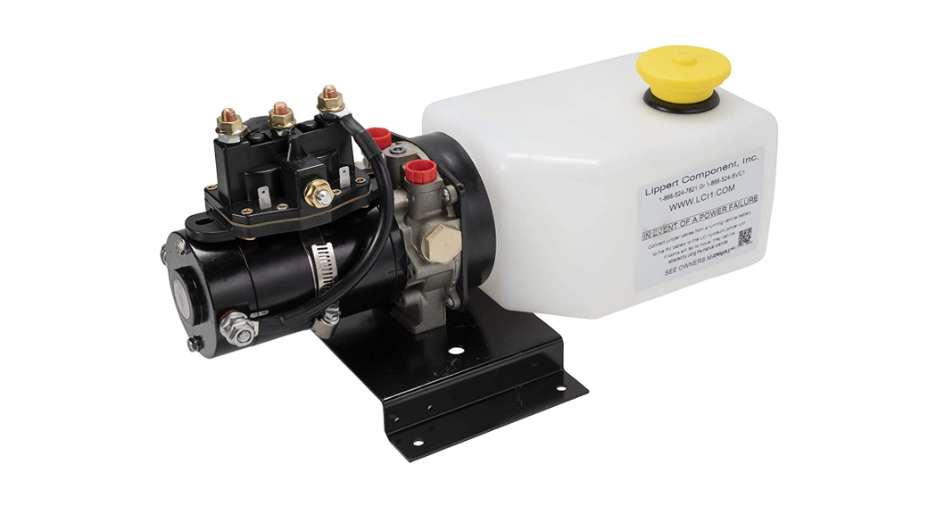
Fluid RecommendationThe Lippert Electronic Leveling System is pre-filled, primed, and ready to operate directly from the manufacturer. Type “A” Automatic Transmission Fluid (ATF) is utilized and will work. ATF with Dexron III® or Mercon 5® or a blend of both is recommended by Lippert Components, Inc.In colder temperatures (less than 10° F) the jacks may extend and retract slowly due to the fluid’s molecular nature. For cold weather operations, fluid specially formulated for low temperatures may be desirable. For a list of approved fluid specifications, see TI-188.
- Remove Breather/Fill Cap (Fig. 2).
- Pour ATF into Breather/Fill opening.NOTE: Do not allow any contamination into the reservoir during the filling process.NOTE: Standard reservoir holds approximately 2 quarts (1.89 liters) of ATF.
- Fill to within ½” of the top.
- Replace Breather/Fill cap when finished.NOTE: The system is self-purging. By simply cycling the system 2-3 times, any air in the system will be forced back to the reservoir and out of the Breather/Fill cap.
Adjusting room so it seals in the IN position
- Locate cylinder coming through the frame.
- The run room is partially out.
- Hold jam nut (Fig. 3A) in place with a wrench.
- Adjust nylon locking nut (Fig. 3C) towards the bracket if the room does not seal. Adjust the nylonlocking nut (Fig. 3C) away from the bracket if the room is too tight and damages the fascia.NOTE: Make small adjustments, running the room in after each adjustment until the proper seal is achieved.
Adjusting room so it seals in the OUT position
- Locate cylinder coming through the frame.
- Extend room completely out.
- Check the inside fascia and seal positioning.
- Partially retract room.
- Loosen and back off jam nut (Fig. 3A) from the nut (Fig. 3B) to give nut (Fig. 3B) room for adjustment.
- Adjust nut (Fig. 3B) away from the bracket if the room extends too far and damages the inside fascia.Adjust nut (Fig. 3B) towards the bracket if the room does not seal.NOTE: Make small adjustments, running the room out after each adjustment until the proper seal is achieved.
- Tighten jam nut (Fig. 3A) to nut (Fig. 3B).
NOTE: 2″ to 3″ of free travel is normal.
Mechanical Room AdjustmentNOTE: All slide-out room adjustments must be performed by certified service technicians. Adjustmentsmade by non-certified persons may void any and all warranty claims.
Horizontal Adjustment
- Loosen carriage bolts (Fig. 4A) on each bracket located at the end of each guide tube.
- The room is ready to be positioned horizontally by pushing on the outside, sidewall or by using a prying device inserted into the opening between the room and coach.
NOTE: Use caution when using a prying device so seals do not become damaged.
Vertical Adjustment
- Loosen 2 carriage bolts (Fig. 4A) on each bracket located at the end of each guide tube.
- Loosen jam nut (Fig. 5A).
- For vertical adjustment turn the vertical adjustment bolt (Fig. 5B) up or down to locate room height.
- Once room height is located, tighten carriage bolts (Fig. 4A) and jam nuts (Fig. 5A).
Synchronizing Room Travel
The Lippert Hydraulic Slide-out System room travel (both sides of the room traveling the same distance) can be adjusted with a specially designed synchronizing bracket mounted on the passive slide tube. The passive slide tube is the one that is not powered. The active slide tube is the one that has the cylinder attached. Ifone side of the room fails to seal adjust as follows:
- Extend the slide-out about halfway out.
- Measure the active side from the “T”-molding on the slide-out back to the outside wall of the coach.
- Then, measure the passive side in the same manner.
- Loosen bolts (Fig. 6B) on top of the passive slide tube (Fig. 6A).
- Push or pull room (on the passive side) to align the passive side with the active side.
- Tighten bolts (Fig. 6B) to secure the passive side position.
- Retract room and run as normal.
Manual OverrideThe Lippert Hydraulic Slide-out System can be run with an auxiliary power device like an electric or cordless drill. In the event of an electrical or system failure, this manual method of extending and retracting the slideout room can be used. A standard hand-held drill is all that is required. A standard 38″ room will take approximately 45 seconds to retract. See the instructions below.
- Remove protective label (Fig. 7A).
- Using a standard hex bit and auxiliary drive device (cordless or electric drill), insert hex bit into coupler found under the protective label (Fig. 8).
- Run drill counterclockwise to extend the slide-out room and clockwise to retract the slide-out room.
report this ad
![]()
![]() The contents of this manual are proprietary and copyright protected by Lippert Components, Inc. (“LCI”). LCI prohibits the copying or dissemination of portions of this manual unless prior written consent from an authorized LCI representative has been provided. Any unauthorized use shall void any applicable warranty. The information contained in this manual is subject to change without notice and at the sole discretion of LCI.
The contents of this manual are proprietary and copyright protected by Lippert Components, Inc. (“LCI”). LCI prohibits the copying or dissemination of portions of this manual unless prior written consent from an authorized LCI representative has been provided. Any unauthorized use shall void any applicable warranty. The information contained in this manual is subject to change without notice and at the sole discretion of LCI.
Revised editions are available for free download from lci1.com.Please recycle all obsolete materials.For all concerns or questions, please contact Lippert Components, Inc.Ph: (574) 537-8900 | Web: lci1.com | Email: [email protected]
References
[xyz-ips snippet=”download-snippet”]