LIPPERT Power Gear Bunk Lift
![]()
IntroductionSystem DescriptionThe Power Gear Slim Rack Bunk Lift System with Controller 1510000199 or 1510000260 is a rack and pinion design operated by a pair of 12V DC electric motors. The system is designed to move a bunk of no more than 100 pounds vertically. Bunk lift systems rated for higher weight or longer strokes can be obtained. Please contact Lippert Components Customer Service by phone at (574) 537-8900 or by email at [email protected] for application assistance. Figure 1 indicates possible bunk lift and motor locations.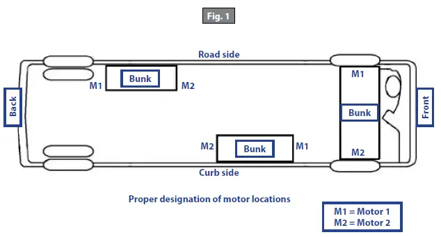
Major Components
- Wall switch with indicator LEDs that mounts to the wall (Fig. 2). The wall switch communicates with the controller to allow bunk movement and provides end user feedback via LEDs.

- “UP” and “DOWN” buttons (Fig. 2) move the bunk lift in the corresponding direction when button is pressed. Push and hold until bunk reaches pre-programmed stop point.
- “ENGAGE PARK BRAKE” will light red if park brake is not engaged when trying to operate the bunk lift.
- “LOW VOLTAGE” LED will light red when the voltage is below the operating threshold of the controller.
- “FAULT CODE” LED will flash red a certain number of times to alert user of specific fault conditions. Refer to the Troubleshooting Chart.
- “BUNK LIFT MOVEMENT” LED will flash green when the bunk lift is moving.
- A specially-designed controller that gives the user full control of the bunk movement, up or down. The controller has programmed stops that control the motor when the bunk is fully raised or lowered, and the ability to detect faults for ease in troubleshooting (Fig. 3).
- Two to four channels with 12V DC gear motors, which mount to the bunk, and gear rack arms that mount to the vertical structure (Fig. 3).
- Harnesses (not shown) to connect wall switch and motors to controller.
WARNING:
- Obstructions in the bunk lift’s path can cause severe property damage, serious personal injury or death. Always make sure that the bunk lift path is clear of people and objects before and during operation of the bunk lift.
- Always keep away from the gear racks when the bunk lift is being operated. The gear assembly may pinch or catch on loose clothing causing personal injury.
- Do not operate bunk lift with anyone physically lying or sitting in the bunk. Obstructions in the bunk lift’s path can cause severe property damage, serious personal injury or death.
Operation
Note: The bunk lift system will not function until the stops are properly programmed, or faults are cleared.OEM coach manufacturer will complete programming during installation.
- The GREEN LED (Fig. 2) indicates the system operation.
- A solid GREEN LED indicates bunk movement.
- The RED LED (Fig. 2) indicates a fault or a problem with the system. Refer to the Troubleshooting Chart for additional information.
Lowering the Bunk
- The engine or generator must be running, or plugged in to shore power.
- Transmission must be in PARK or NEUTRAL (if equipped.)
- Level the unit (if equipped).
- Remove the locking pins (if equipped).
- Turn on the on/off switch or key (if equipped).
- Press and hold the “DOWN” button on the wall switch (Fig. 2). A slight delay is normal before the bunk begins to move.
- Release the button when the bunk is fully lowered and stops moving.
- Turn on the on/off switch or key (if equipped).
Raising the Bunk
- The engine or generator must be running or plugged in to shore power.
- Transmission must be in PARK or NEUTRAL (if equipped).
- Remove locking pins (if equipped).
- Turn on the on/off switch or key (if equipped).
- Press and hold the “UP” button on the wall switch (Fig. 2). A slight delay is normal before the bunk begins to move.
- Release the button when the bunk is fully raised and stops moving.
- Turn on the on/off switch or key (if equipped).
- Install the locking pins (if equipped).
Maintenance
The Power Gear Slim Rack Bunk Lift System has been designed to require very little maintenance. To ensure the long life of the bunk lift system, read and follow these few simple procedures:
- When the bunk is in the down position, visually inspect the gear rack assemblies. Check for excess build up of dirt or other foreign material; remove any debris items that may be present.
- If the system squeaks or makes any noises, blow out any debris from the gear rack arms and apply a non-silicone based dry lubricant to prevent and/or stop squeaking.
Troubleshooting
- The controller has the ability to detect several faults, which will be displayed by the wall switch. When a fault is detected, the bunk movement will stop and two different LEDs will flash in a pattern.
- The “FAULT CODE” LED (Fig. 2) on the wall switch will flash RED a number of times corresponding to a specific fault code.
- The “BUNK LIFT MOVEMENT” LED on the wall switch (Fig. 2) will flash GREEN a number of times corresponding to which motor had the associated fault. I. For example: if four RED flashes and two GREEN flashes are seen, it means that there is a motor fault on Motor 2.
- There are two types of faults, MINOR and MAJOR, and fault must be cleared in order for the bunk to operate. Refer to the Troubleshooting Chart to best determine what caused the fault.
- MINOR faults can be cleared by pushing and releasing the “UP” or “DOWN” buttons on the wall switch (Fig. 2).
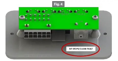
- After the problem has been repaired, MAJOR faults must be cleared by pushing and releasing the “SET STOPS/CLEAR FAULTS” button located on the back of the wall switch (Fig. 4).Note: For MAJOR faults, the controller must be overridden by following one of the “Emergency Bunk Movement” procedures. The controller will then have to be re-programmed by an OEM-authorized dealer when the problem is repaired.
Troubleshooting Chart Fault Code Fault Type Description Possible Cause Possible Solutions 1
Major
Stops Not Programmed
• Stops have not been set • Stops were cleared
• Stops were
improperly set
Stops need to be programmed.
2
Minor
System Fault
• Obstruction present
• Excessive system drag
Run bunk lift in opposite direction. If bunk continues to move in the opposite direction, remove obstruction, excessive weight in bunk or repair damaged component. If bunk stops moving in opposite direction, observe fault code and refer to this
chart.
4
Major
Motor Fault
• Bad wire connection
• Bad motor
• Check all connections at controller and motor. • Check the harness for broken wires.
• Put 12V DC to the motor. If it does not run, replace the motor.
6
Minor
Excessive Battery Voltage Supply voltage to the controller is 17V DC or greater. Consult manufacturer of charging system for troubleshooting assistance.
Override Modes
WARNING:
- Obstructions in the bunk lift’s path can cause severe property damage, serious personal injury or death. Always make sure that the bunk lift path is clear of people and objects before and during operation of the bunk.
- Always keep away from the gear racks when the bunk lift is being operated. The gear assembly may pinch or catch on loose clothing causing personal injury.
In the event of component failure or loss of system power, the bunk can be manually overridden and bunkmoved for travel.Note: At any time during the override procedure, the system will exit this mode if the bunk has not been moved for two minutes or if a fault is detected during bunk movement. The “FAULT CODE” and “BUNK MOVEMENT” LEDs will flash rapidly for 10 seconds to indicate that the override procedure failed. After the 10 seconds of flashing, the controller will automatically default to “FAULT CODE 1 (see Troubleshooting Chart) and programming must be restarted.Note: The bunk controller must be re-programmed by an OEM-authorized dealer after the system has been overridden.
Emergency Bunk Movement to ‘UP’ PositionUse this procedure when there is NO loss of power or electrical problem with the system.
- Remove the wall switch (Fig. 2) from the wall.
- Prior to clearing the MAJOR fault, record the number of RED and GREEN flashes observed on the wallswitch. This information will help the dealer/service center in troubleshooting the bunk lift system.
- Press and hold the “SET STOPS/CLEAR FAULTS” button (Fig. 4) on the back for the wall switch for five seconds. Both RED and GREEN LEDs will be on solid while this button is pressed. After five seconds, the GREEN LED will begin flashing and the RED LED will remain lit.
- The system is now ready to raise the bunk. Press and hold the BUNK LIFT MOTOR buttons 1 and 2 on the back of the Wall Switch (Fig. 5).CAUTION: It is very important to note that during this procedure, the bunk lift controller has NO stop locations. Damage to the bunk lift can occur if the bunk is raised or lowered too far.
- Press the “UP” button on the front of the wall switch until the bunk is in the fully raised position. If one side of the of the bunk needs to be raised further in order to fully raise, press and hold the motor button corresponding to only the motor you want to move. Press the “UP” button on the front of the wall switch to raise the bunk the remainder of the way. Install lock pins (if equipped).
- Re-install the wall switch.
- Take the unit to an OEM-authorized dealer for repairs.
Manual Emergency Bunk Movement to ‘UP’ Position
In the event that power is lost to the bunk motor(s) or the “Emergency Bunk Movement to ‘UP’ Position” procedure does not work, use the following steps to manually raise the bunk.
- Use a voltmeter and check to see if power is being delivered to the controller.
- If no DC power is being delivered from coach, use another 12V DC battery power source to power the module and retract the bunk using the “UP” button on the wall switch.
- If power source is not available, use the following steps:
- Gain access to channel assemblies on each side of the bunk by first contacting the OEM manufacturer for access details.
- Once access is gained, remove the top cover plate of each channel assembly.
- Unhook the motor retention spring (Fig. 6A).Note: Some older systems may have a motor retention screw instead of a motor retention spring. Loosen the motor retention screw. Do not remove the screw.
- Remove each motor from the channel assembly. Bunk will drop if in the raised position.
- Disconnect motor connectors and place motors in a safe location. They will be needed when bunk lift is serviced.
- Manually push up bunk lift.
- When bunk is in the fully raised position, install pins to keep it in place. Contact bunk lift OEM for details.Note: The bunk lift must be inspected at an OEM-authorized dealer for troubleshooting and repairs. The bunk controller must be re-programmed by an OEM-authorized dealer after the system has been overridden.
 report this ad
The contents of this manual are proprietary and copyright protected by Lippert Components, Inc. (“LCI”). LCI prohibits the copying or dissemination of portions of this manual unless prior written consent from an authorized LCI representative has been provided. Any unauthorized use shall void any applicable warranty. The information contained in this manual is subject to change without notice and at the sole discretion of LCI. Revised editions are available for free download from lci1.com.Please recycle all obsolete materials.For all concerns or questions, please contactLippert Components, Inc.Ph: (574) 537-8900 | Web: lci1.com | Email: [email protected]![]()
References
[xyz-ips snippet=”download-snippet”]