Electric Motor Slide-outOWNER’S MANUALby Lippert Components®
Introduction
The electric slide-out system is designed to provide years of trouble-free operation and reflects the latest state-of-the-art technology.
NOTE: Information for this document was obtained from Power Gear manual #82-S0380 Rev. 0B issuedMay 2008. All information has been updated for current practices.
Read, study and understand all instructions in this manual before operating the electric motor-driven slide-out system.
Major ComponentsThe slide-out system is a rack and pinion design operated by a 12 V DC electric motor.
- Inner rail assemblies are designed to support the room weight.
- The 12 V DC gear motor will operate the room using power from the onboard unit battery.
- Slide-out systems are equipped with a manual override that extends or retracts the room in the event of a loss of power.
Safety
Always make sure that the slide-out room path is clear before and during the operation of the slide-out room.Always keep away from the slide-out rails when the room is being operated. The gear assembly may pinch or catch on loose clothing causing personal injury.
Always utilize a room locking device on the slide-out room during storage and transportation.
Failure to follow these instructions could result in serious injury or death.
Operation
Extending the Room
- Level the coach.
- Verify the battery is fully charged and hooked up to the electrical system.
- If so equipped, remove the transit bars.
- Make sure the room path is clear, both inside and outside the coach.
- Check the slide-out awning. Some awnings must be manually unlocked before operating the slide-out.
- Press and hold the IN/OUT switch in the OUT position until the room is fully extended and stops moving.
- Release the switch, which will lock the room into position.
Retracting the Room
- Verify coach is level.
- Verify the battery is fully charged and hooked up to the electrical system.
- Make sure the room path is clear, both inside and outside the coach.
- Press and hold the IN/OUT switch in the IN position until the room is fully retracted and stops moving.
- Release the switch, which will lock the room into position.
- Check the slide-out awning. Some awnings must be manually locked before traveling.
- If so equipped, install transit bars.
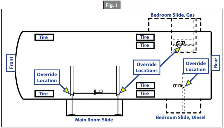
Manually Overriding the Slide-OutYour slide-out system is equipped with a manual crank override that extends or retracts the room in the event of a loss of power (Fig.1.)The crank model uses a 3/4″ ratchet or wrench to turn the 3/4″ hex head override nut located on the motor’s gearbox (Fig. 3).
NOTE: Optionally, it is permissible to use an adjustable wrench on the square drive shaft to crank the room in or out (Fig. 2).
If the room does not move when the switch is pressed, check the following:
- The battery is fully charged and connected.
- The transit bars are removed.
- All system fuses/circuit breakers and relays are good.
 After the previous items have been checked and the room still does not move when the slide-out switch is pressed, follow these simple steps to manually override the slide-out room.
- Locate applicable slide-out motor from Figure 1.A. The motor is located at the top of the center storage compartment under the slide-out room.B. A bedroom slide-out motor will be mounted to the rail assembly.
- In slide-out motors built after 2009, brake levers are equipped with a spring lock.
Do not remove the rubber boot. Removal of the boot will void the manufacturer’s warranty.A. Do not remove the rubber boots when engaging or releasing the brake lever.B. When viewed from the end of the motor (Fig. 4), depress the spring lock lever on the right-hand side of the boot cover.NOTE: In slide-out motors built prior to 2009, brake levers are not equipped with a spring lock.C. Rotate the override lever counterclockwise approximately 30 degrees until the brake lever stops against the brake’s set screw while contacting with the spring lock.
- The room is now free to move.
- Locate the manual override on the end of a rail assembly (Fig. 2). It is also permissible to use an adjustable wrench on the square drive shaft (Fig. 2) to crank the room in or out.
- Check the slide-out awning. Some awnings must be manually unlocked before operating.
- Using a 3/4″ wrench or ratchet, crank the room either in or out completely, depending on need.
- When the room is fully in or out, apply pressure to the wrench or ratchet, then return the motor brake lever to the “Engaged” position. This will ensure the room is locked into a seated position.
When the motor brake is disengaged, the slide-out room will not lock in place; therefore, the room will not be sealed. When the room has been manually retracted, be sure to install the transit bars and return the motor brake lever to its normal “engaged” position in order to seal and lock the room into position.

- Again, check the slide-out awning. Some awnings must be manually locked before traveling.
- If so equipped, re-install transit bars.
- Take the coach to an authorized dealer for service.
Maintenance
The slide-out system has been designed to require very little maintenance. To ensure the long life of the slide-out system read and follow these few simple procedures.
Do not work on the slide-out system unless the battery is disconnected.
- When the room is out, visually inspect the inner slide rail assemblies. Check for the excess build-up of dirt or other foreign material; remove any debris or items that may be present.
- If the system squeaks or makes any noises, it is permissible to apply a light coating of silicone spray or lithium grease to the roller and bearing sleeve ID. Remove any excess lubricant so that dirt or debris does not build up.
- DO NOT lubricate the slide-out drive gears, gear racks, or roller O.D. as this will attract dirt or debris.
report this ad
The contents of this manual are proprietary and copyright protected by Lippert Components, Inc. (“LCI”). LCI prohibits the copying or dissemination of portions of this manual unless prior written consent from an authorized LCI representative has been provided. Any unauthorized use shall void any applicable warranty. The information contained in this manual is subject to change without notice and at the sole discretion of LCI.
Revised editions are available for free download from lci1.com.
Please recycle all obsolete materials.
For all concerns or questions, please contact Lippert Components, Inc.Ph: (574) 537-8900 | Web: lci1.com | Email: [email protected]
Rev: 04.04.19CCD-0001615
References
[xyz-ips snippet=”download-snippet”]