LIPPERT PSX1 Power Stabilizing System Owner’s Manual
System Description
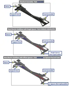
The PSX1™ is a 12V DC electric motor-driven system. The electric motor drives Acme-threaded screws to extend and retract the stabilizer legs to stabilize the trailer.The stabilizing system can be installed on travel trailers and 5th Wheels. Travel trailer options include both front and rear stabilizers or a rear stabilizer only, while 5th Wheels typically utilize only a rear stabilizer. The standard duty stabilizer is suitable for all trailers.There are no serviceable parts within the electric motor. If a motor fails, it must be replaced. Disassembly of the motor voids the warranty. Mechanical portions of the PSX1™ are replaceable. Contact Lippert Components, Inc. to obtain replacement parts.
Safety Information
The PSX1™ is intended for the purpose of stabilizing the trailer after the trailer has been leveled. The use of this system for any reason other than which it is intended is prohibited by Lippert’s Limited Warranty and may result in serious personal injury or death. The PSX1™ is designed as a stabilizing component system and should not be used to provide service under the trailer for any reason such as changing tires or repairing or replacing any components beneath the trailer.
![]() The “WARNING” symbol above is a sign that an installation procedure has a safety risk involved and may cause death, serious personal injury or severe product or property damage if not performed safely and within the parameters set forth in this manual. Always wear eye protection when performing this installation procedure. Other safety equipment to consider would be hearing protection, gloves, and possibly a full face shield, depending on the nature of the installation procedure.
The “WARNING” symbol above is a sign that an installation procedure has a safety risk involved and may cause death, serious personal injury or severe product or property damage if not performed safely and within the parameters set forth in this manual. Always wear eye protection when performing this installation procedure. Other safety equipment to consider would be hearing protection, gloves, and possibly a full face shield, depending on the nature of the installation procedure.
![]() Lippert Components Inc. recommends that a trained professional be employed to change the tires on the trailer. Any attempts to change tires or perform other service while trailer is supported by the PSX1 could result in death, serious personal injury or severe product or property damage.
Lippert Components Inc. recommends that a trained professional be employed to change the tires on the trailer. Any attempts to change tires or perform other service while trailer is supported by the PSX1 could result in death, serious personal injury or severe product or property damage.
![]() Failure to act in accordance with the following may result in death, serious personal injury or severe product or property damage. Always make sure the stabilizer area is clear of pets, people and objects before and during operation of the system. Always keep away from the stabilizer legs when in operation.
Failure to act in accordance with the following may result in death, serious personal injury or severe product or property damage. Always make sure the stabilizer area is clear of pets, people and objects before and during operation of the system. Always keep away from the stabilizer legs when in operation.
![]() The PSX1 is to be used for stabilizing the trailer, not leveling the trailer. The stabilizer legs should never be extended longer than two seconds beyond initial contact with the ground.
The PSX1 is to be used for stabilizing the trailer, not leveling the trailer. The stabilizer legs should never be extended longer than two seconds beyond initial contact with the ground.![]() Never lift the trailer completely off the ground. Lifting the trailer completely off the ground creates an unstable condition that could result in property damage and personal injury.
Never lift the trailer completely off the ground. Lifting the trailer completely off the ground creates an unstable condition that could result in property damage and personal injury.
Preparation
The PSX1 is intended for the purpose of stabilizing the trailer after the trailer has been leveled.
- Make sure the trailer is on solid, level ground.
- Clear all stabilizer leg landing locations of debris and obstructions. Locations should also be free of depressions.
- When parking the trailer on extremely soft surfaces, utilize load distribution pads under each stabilizer leg.
- People and pets should be clear of trailer while operating the stabilizers.
Extending Stabilizers
- Make sure the trailer is level.
- Verify the battery is fully charged and hooked up to the electrical system.
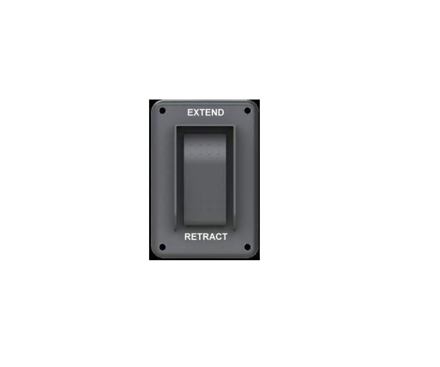
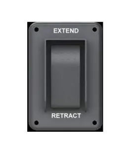
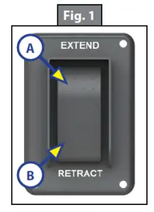
- Press and hold “EXTEND” on the switch (Fig. 1A) for the rear stabilizer until the footpads of the stabilizer legs contact the ground and the rear of the trailer is stabilized. Then release the switch.
- If a front stabilizer is installed, press and hold “EXTEND” on the switch (Fig. 1A) for the front stabilizer until the footpads of the stabilizer legs contactthe ground and the front of the trailer is stabilized. Then release the switch.
![]() Once the stabilizer legs have been extended, do not use the tongue jack on a travel trailer or the landing gear on a 5th Wheel. Damage to the stabilizer legs can occur when lifting or leveling the trailer after the stabilizer legs have been extended. Doing so will void the warranty of the stabilizers.
Once the stabilizer legs have been extended, do not use the tongue jack on a travel trailer or the landing gear on a 5th Wheel. Damage to the stabilizer legs can occur when lifting or leveling the trailer after the stabilizer legs have been extended. Doing so will void the warranty of the stabilizers.
Retracting Stabilizers
- Verify the battery is fully charged and hooked up to the electrical system.
- If a front stabilizer is installed, press and hold “RETRACT” on the switch (Fig. 1B) for the front stabilizer until the stabilizer legs are fully retracted. Then release the switch.
- Press and hold “RETRACT” on the switch (Fig. 1B) for the rear stabilizer until the stabilizer legs are fully retracted. Then release the switch.
Stabilizing System
By keeping the “EXTEND” switch (Fig. 1A) engaged for one to two seconds after the legs’ footpads make contact with the ground, the trailer will be stabilized and ready for use. In the event the system shuts off while trying to stabilize the trailer, an in-line auto-reset circuit protection has tripped and will reset within 10 seconds. This is an indication the PSX1™ is not being used as intended and is trying to lift too much weight.Note: Make sure the stabilizer legs are fully retracted before moving the trailer.
Manual Override
The PSX1 comes with a manual override system located on the stabilizer end opposite the electric motor (Fig. 2A).To manually operate the stabilizer:
- Disconnect one of the wire leads from the motor to prevent backfeeding the motor.
- Next, insert the 1/2” diameter manual crank handle (PN #119226) (Fig. 3) over the coupler and pin at theend of the stabilizer (Fig. 2A). The slot in the end of the crank handle (Fig. 3) accommodates the pin on the coupler (Fig. 2A) to allow the manual extension/retraction of the stabilizer legs.
![]() The gears can be stripped if the stabilizer legs are retracted/extended to the fullest extent and the operatorcontinues to rotate the manual override. Do NOT use a power tool to extend or retract stabilizers.Rotate the crank handle clockwise to extend or counterclockwise to retract the stabilizer legs.
The gears can be stripped if the stabilizer legs are retracted/extended to the fullest extent and the operatorcontinues to rotate the manual override. Do NOT use a power tool to extend or retract stabilizers.Rotate the crank handle clockwise to extend or counterclockwise to retract the stabilizer legs.
System Maintenance
![]() Do not work on the stabilizer unless the battery is disconnected. Failure to act in accordance with the following may result in death, serious personal injury or severe product or property damage.
Do not work on the stabilizer unless the battery is disconnected. Failure to act in accordance with the following may result in death, serious personal injury or severe product or property damage.
Mechanical Maintenance
It is recommended that when operating in harsh environments, e.g. road salt or ice buildup, the moving parts be kept clean. They can be washed with mild soap and water. The ACME screw is precoated with grease. If the screw is cleaned, it may be necessary to add grease to the screw to ensure smooth stabilizer operation.
![]() Operating the stabilizer without grease on the screw could lead to product failure.
Operating the stabilizer without grease on the screw could lead to product failure.
Electrical Maintenance
For optimum performance, the system requires full battery current and voltage. The battery must be maintained at full capacity. Other than good battery maintenance, check the terminals and other connections at the battery, the control switch and the electric motors for corrosion and loose or damaged terminals. Check motor leads under the trailer chassis. Since these connections are subject to damage from road debris, make sure they are in good condition.
Troubleshooting
| What Is Happening? | Why? | What Should Be Done? |
| System shuts off | Too much weight. | Circuit protection will reset in 10 seconds. |
|
Switch does not activate system |
Low voltage. | Test battery voltage under load. Charge or replace. |
| Use Manual Override. | ||
| Damaged or disconnected wiring. | Check wiring. Repair or replace. | |
| Use Manual Override. |
PSX1 ELECTRIC STABILIZER ASSEMBLIES
LEVELING AND STABILIZATION
PSX1 ELECTRIC STABILIZER COMPONENTS
LEVELING AND STABILIZATION
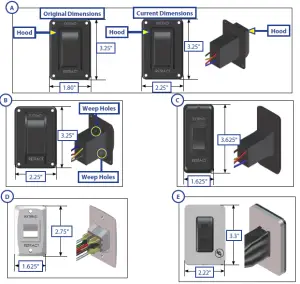
| Callout | Part # | Description |
| A | 387874 | IP 66 Electric Stabilizer Switch with Harness |
| B | 344484* | Waterproof Electric Stabilizer Switch with Harness (OBSOLETE – Use 387874) |
| C | 242409* | Waterproof Electric Stabilizer Switch with Harness (OBSOLETE – Use 387874) |
| D | 144214 | Non-Waterproof Electric Stabilizer Switch with Bezel and Harness |
| E | 138415 | Non-Waterproof Electric Stabilizer/Hydraulic Landing Gear Switch |
| NOTE: * When purchasing a switch for exterior use without a waterproof enclosure box, purchase 387874. |
PSX1 ELECTRIC STABILIZER COMPONENTS
LEVELING AND STABILIZATION
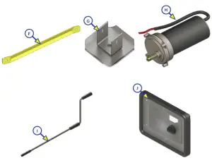
| Callout | Part # | Description |
| F | 1134121 | Black Support Arm |
| 1134122 | Yellow Support Arm | |
| G | 157584 | Foot Assembly |
| 372980 | Foot Assembly | |
| H | 138445 | Klauber C800 Motor (With Plastic Cover) |
| 352338 | Electric Stabilizer Motor | |
| I | 119226 | Jack Crank Handle |
| J | 258403 | Hatch Cover – Black |
| 134025 | Hatch Cover – White |

 report this ad
The contents of this manual are proprietary and copyright protected by Lippert Components, Inc. (“LCI”).LCI prohibits the copying or dissemination of portions of this manual unless prior written consent from an authorized LCI representative has been provided. Any unauthorized use shall void any applicable warranty. The information contained in this manual is subject to change without notice and at the sole discretion of LCI. Revised editions are available for free download from lci1.com.Please recycle all obsolete materials.For all concerns or questions, please contactLippert Components, Inc.Ph: (574) 537-8900 | Web: lci1.com | Email:
Read More About This Manual & Download PDF:
References
[xyz-ips snippet=”download-snippet”]