
![]()
MANUALInstallation Instructions
Trough- O- Matic Automatic Plastic Float ValveTM825/ TM825T/ TM825AS
- Sturdy adjustable brackets tighten down with thumbscrews and make installation on edge of troughs and tanks fast and easy.
- Accepts standard 3/4″ garden hose thread. Direct pipe installation quickly achieved with 3/4″ adapter (not included).
- One-piece float molded from durable maintenance-free polyethylene.
- Adjustable neoprene valve seat delivers long life (Models TM825 & TM825T).
- Longer float leverages up to 55 psi water pressure with 245 gallons per hour capacity.
Each Automatic Float Valve Contains:
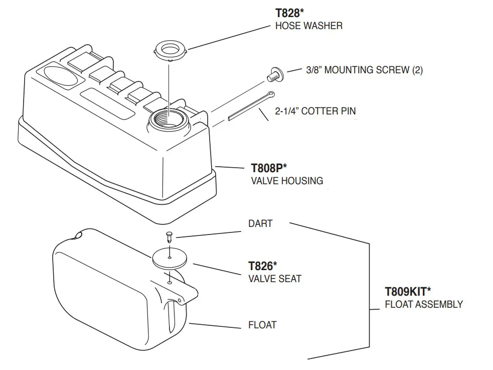
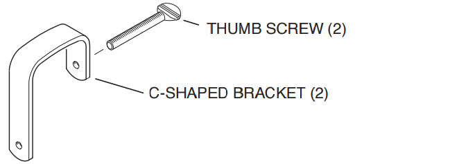
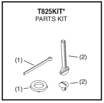
1 Plastic Valve Housing1 Hose Washer (already assembled)1 Float Assembly1 Large Cotter Pin 1/8” x 2-1/4”2 C-Shaped Brackets2 Thumb Screws 1/4”-20 x 2”2 Mounting Screws 1/4”-20 x 3/8” (TM825)2 L-Shaped Brackets (TM825T & TM825AS)4 Mounting Screws 1/4”-20 x 3/8”(TM825T &TM825AS)4 Self Tapping Screws #10 x 3/4”(TM825T & TM825AS)1 Anti-Siphon Valve Stem (TM825AS)1 Anti-Siphon Valve Housing (TM825AS)1 Plastic Orifi ce Insert (already assembled)(TM825AS)1 Small Cotter Pin 1/8” x 1-1/8” (TM825AS)
Tools Required:
Straight Blade Screw DriverPhillips Head Screw DriverNeedle Nose Pliers
Assembly Instructions (Models TM825 & TM825T):
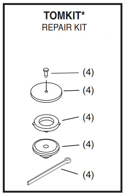
- Familiarize yourself with all of the automatic fl oat valve components.a. Open the loose parts bag and inventory the contents.b. Install the hose washer in the valve housing. Make sure the washer isfi firmly seated against the valve housing.c. The rubber valve seat is already pinned to the fl oat. Make sure the seat and pin are fi firmly seated against the fl oat.
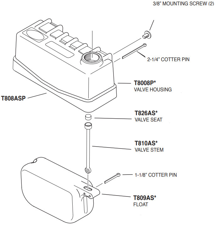
- Position the fl oat assembly inside the valve housing and slide the large 2-1/4” cotter pin through the housing and the fl oat ssembly (see Figure 1). Spread the ends of the large cotter pin open slightly with pliers. When properly installed, the fl oat assembly shouldpivot freely on the cotter pin inside the valve housing.
- See Mounting Instructions.

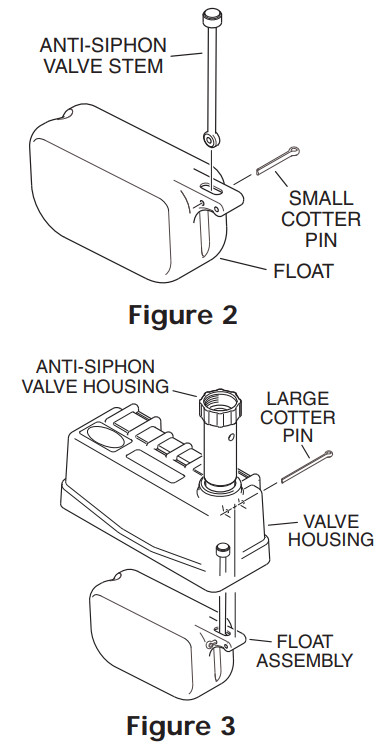
Assembly Instructions (Models TM825AS):
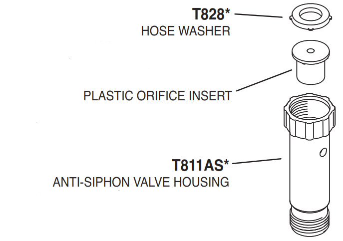
- Familiarize yourself with all of the automatic fl oat valve components.a. Open the loose parts bag and inventory the contents.b. The plastic orifi ce insert and hose washer is already assembled in the anti-siphon valve housing. Make sure the orifi ce insert and washer are fi rmly seated against the anti-siphon valve housing.
- Position the anti-siphon valve stem assembly in the slot of the oat and slide the 1-1/8” cotter pin (smallest of the two cotter pins) through the fl oat and the valve stem assembly (see Figure 2) then spread the end of the cotter pin open slightly. When properly installed, the valve stem assembly should pivot freely on the cotter pin inside the fl oat.
- Thread the anti-siphon valve housing all the way into the valve housing.
- Position fl oat assembly inside valve housing and slide the large 2-1/4” cotter pin through the housing and the fl oat assembly (see Figure 3). Spread the ends of the large cotter pin open slightly with pliers. When properly installed, the fl oat assembly should pivot freely on the cotter pin inside the valve housing.
- See Mounting Instructions.
Mounting Instructions:
Standard Rim Tank Mounting (All Models):
1. Slide both C-shaped brackets into the valve housing as shown (see Figure 4).Note: Use the upper mounting holes in the valve housing to maintain a water level about 4” below the rim. Use the lower mounting holes in the valve housing to maintain a water level about 2-3/8” below the rim.2. Attach each C-shaped bracket to the valve housing with the 3/8” mounting screws.3. Connect the water supply line.4. Position the automatic fl oat valve assembly over the tank rim.5. Thread the thumbscrews through the C-shaped brackets and tighten.6. Test automatic fl oat valve operation.
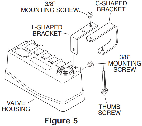
 Wide Rim Tank Mounting (Models TM825T & TM825AS):
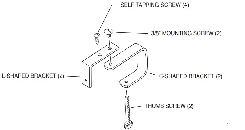
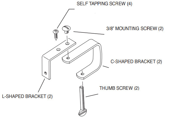
- Slide both L-shaped brackets into the valve housing as shown (see Figure 5).
- Attach each L-shaped bracket to the valve housing with the 3/8” mounting screws.
- Attach a C-shaped bracket to each L-shaped bracket with the 3/8” mounting screws.Note: There are two positions on the L-shaped bracket which allows you to adjust for varying rim widths.
- Connect the water supply line.
- Position the automatic fl oat valve assembly over the tank rim.
- Thread the thumbscrews through the C-shaped brackets and tighten.
- Test automatic fl oat valve operation.
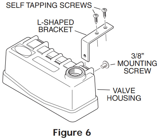
 Extra Wide Rim Tank Mounting (Models TM825T & TM825AS):
- Slide both L-shaped brackets into the valve housing as shown (see Figure 6).
- Attach each L-shaped bracket to the valve housing with the 3/8” mounting screws.
- Connect the water supply line.
- Position the automatic fl oat valve assembly over the tank rim.
- Attach each L-shaped bracket to the tank rim with two (2) self-tapping screws.Note: Pre-drill the tank rim at the desired automatic fl oat valve mounting location with a 1/8” drill if necessary.
- Test automatic fl oat valve operation.
See Page 4 for Replacement Parts Information
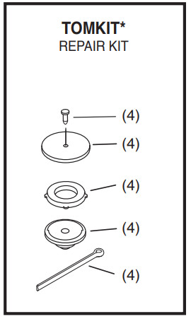
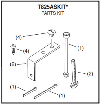
Replacement Parts*/Piezas de repuesto*/Pièces de rechange*
Model TM825
 |
 |
 |
 |
Model TM825T
 |
|
 |
 |
Model TM825AS
 |
 |
 |
 |
 |
Miller Manufacturing Company1450 West 13th Street • Glencoe, MN 55336 • Customer Service 800-260-0888 • FAX 651-982-5101For additional information visit www.miller-mfg.comMiller Manufacturing, Glencoe, MN 55336 USA • www.miller-mfg.com160674_05/18
[xyz-ips snippet=”download-snippet”]