

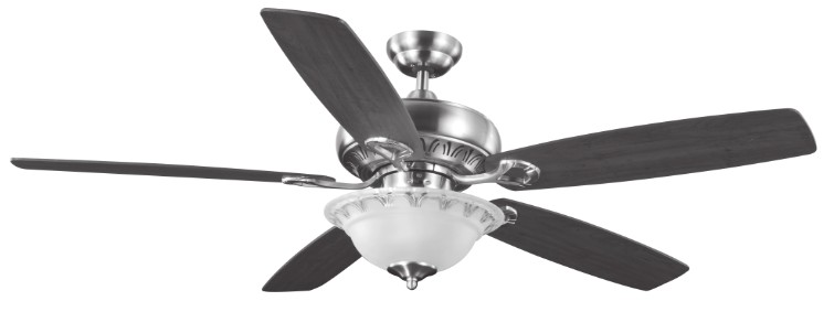
Olympia 52″ ceiling fanModel No . 052-2230-6
Instruction ManualToll-free: 1-877-483-6759IMPORTANT: Please read and understand this manual before any assembly. Before beginning the assembly of this product, make sure all parts are present. Compare parts with an exploded view. If any parts are missing, or if you have any questions, contact customer service at 1-877-483-6759.
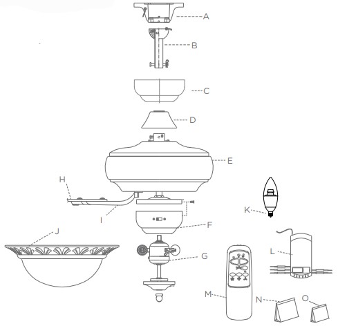
EXPLODED VIEW
| No | Description | Qty |
| A | Mounting Bracket | 1 |
| B | Downrod Assembly | 1 |
| C | Canopy | 1 |
| D | Flange Cover | 1 |
| E | Motor Assembly | 1 |
| F | Switch Housing | 1 |
| G | Light Kit | 1 |
| H | Blade | 5 |
| I | Blade Arm | 5 |
| J | Glass Shade | 1 |
| K | LED Bulbs (E12x7W) | 2 |
| L | Remote Contro | 1 |
| M | Receiver | 1 |
| N | Parts Pack | 1 |
| O | Balance Pack | 1 |
IMPORTANT SAFETY INSTRUCTIONS
Please retain this manual for future reference.
![]() Note: Always turn the power off before servicing the ceiling fan.
Note: Always turn the power off before servicing the ceiling fan.
- A dry dust cloth is suitable for most cleanings.
- Should the ceiling fan become wet, have a qualified electrician inspect it before next use.
- In order to comply with safety regulations and to avoid safety hazards, ceiling fan repairs must becarried out by qualified personnel.
- Pay attention to the ceiling fan blades when cleaning, painting or working nearby.
- Children do not recognize the dangers that may occur when operating ceiling fan. Keep children awayfrom ceiling fans.
DO NOT:
- Expose the ceiling fan to water or immerse it in water.
- Operate the ceiling fan if it shows any signs of damage or if it has been dropped.
- Attempt to remove any parts of the housing or insert any object while the ceiling fan is operating.
- Position the ceiling fan on or near hot surfaces such as stove tops, or near open flames.
- Expose the ceiling fan to rain or moisture. Do not operate the ceiling fan outdoors or with wet hands.
- Use the reverse switch while the fan blades are in motion. This could result in damage to the ceiling fan.
RULES FOR SAFE INSTALLATION
This ceiling fan is designed for household use only and not for commercial applications. No responsibilityis accepted for damage resulting from improper use or noncompliance with the instructions.![]() CAUTION!
CAUTION!
- To avoid possible electric shock, be sure electricity at the fuse box or the circuit breaker is turned off before wiring.
- All wiring must be done in accordance with national and local wiring codes. Consult a qualified electrician to ensure the correct branch circuit conductor.
- Follow the recommended instructions for the proper method of wiring for the new ceiling fan.
- The ceiling fan must be grounded as a precaution against possible electric shock
- If you do not have sufficient electrical wiring knowledge, have the fan installed by a licensed electrician.
- The outlet box and joist must be securely mounted and capable of reliably supporting at least 15.9 kg (35 lbs).
- Mount the lowest moving parts at least 2.1 m (6’11”) above floor or ground level.
- Make sure all electrical connections are sealed with the proper connector and electrical tape inside the outlet box.
- Make sure the ceiling fan is securely fastened to the ceiling.
- All set screws must be checked and re-tightened where necessary before fan operation.
![]() WARNING!
WARNING!
- Mount only to an outlet box marked acceptable for fan support.
- To prevent injur, make sure the fan blades are not bent and that there are no objects within the rotation area.
- The important precautions, safeguards, and instructions appearing in this manual are not meant to cover all possible situations. It must be understood that common sense and caution are factors that cannot be built into the product.
- Not suitable for use with solid-state speed controls.
TOOLS REQUIRED FOR ASSEMBLY
This manual is designed to make it as easy as possible for you to assemble, install, operate and maintain the ceiling fan. The following tools listed are required for assembly and installation.
| 1 star-head screwdriver |  |
1 stepladder | |
| 1 flat-head screwdriver | 1 wire stripper/pliers | ||
| 1 wrench |  |
electrical tape |
After opening the package you should find all the necessary parts for installing this ceiling fan. The box should include: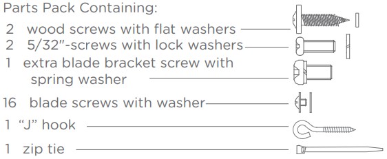
3 balance pieces1 balance clip1 instruction sheet

ASSEMBLY
Preparing for installation
Getting ready
- Unpack and inspect carefully to make sure all parts are included and not damaged (see Fig.1). Lay all pieces out in the working space.
- Turn off power at the fuse box or circuit breaker to avoid possible electrical shock (see Fig.2).

Choosing a location for the ceiling fan
- For effective air circulation, fans should be located in the center of the room, or a minimum of 32″(81.3 cm) from adjacent walls or obstructions.
- Choose a location where there is a high enough ceiling clearance (at least 2.1 m (6’11”) from the floorto the ceiling fan’s slowest moving part).
- Ensure that the outlet box in the room’s ceiling can support the weight of the fan. Typically, if the outlet box is marked acceptable for fan support, it can hold the fan securely.
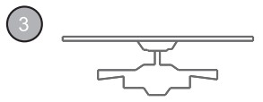
Mounting optionsDrop-mount (for normal ceilings)
- This method is preferred if the ceiling is sloped or vaulted,or if the ceiling is extra high, requiring the need of a download (see Fig. 3).
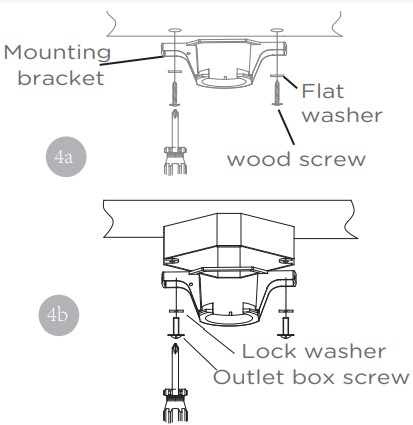
Installation1. Mounting bracket
![]() Note: The mounting bracket depicted will vary depending on the model.
Note: The mounting bracket depicted will vary depending on the model.
- Remove the four sets of side screws from the mounting bracket and save them for future use.Wooden ceiling
- Drill two mounting holes in the ceiling joist. Securely attach the mounting bracket to the ceiling or wooden ceiling as indicated below (fig. 4a).Normal masonry ceiling
- Securely attach the mounting bracket to an outlet box marked “ Acceptable for Fan Support”, using the supplied outlet box screws with lock washers (see Fig. 4b).
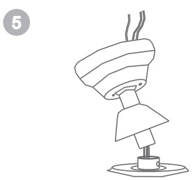
2. Drop-mount![]() Note: Canopy pictures may vary from product for some styles of ceiling fans.Downrod assemblyLoosen the two downrod set screws and remove the clip and connection pin from the downrod coupling. Insert the downrod through the canopy and flange cover, pull lead wires through downrod (see Fig. 5).
Note: Canopy pictures may vary from product for some styles of ceiling fans.Downrod assemblyLoosen the two downrod set screws and remove the clip and connection pin from the downrod coupling. Insert the downrod through the canopy and flange cover, pull lead wires through downrod (see Fig. 5).
Securing assemblyInsert downrod into downrod coupling. Make sure to align holes in downrod with the hole in the coupling. Insert the clip into the connection pin until it snaps into place. Tighten the screws in the downrod coupling(see Fig. 6).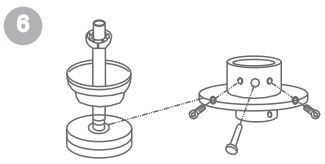
3. Hands-free wiring
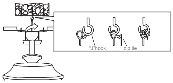
- Carefully lift the fan assembly onto the mounting bracket.
- Rotate the fan until the notch (b) on the aluminum ball fits against the ridge (a) on the mounting bracket (see Fig. 7).
- With the mounting bracket holding the fan assembly, follow wiring instructions (step 4).

NOTE: For added security, attach safety cable from fan unit to “J” hook in outlet box. Secure by looping zip tie through safety cable and “J” hook. Tighten zip tie securely.
 4. Wiring instructions
![]() IMPORTANT: If you are not sure if the electrical outlet box and fan are grounded, contact a licensed electrician for advice. They must be grounded for safe operation.
IMPORTANT: If you are not sure if the electrical outlet box and fan are grounded, contact a licensed electrician for advice. They must be grounded for safe operation.
![]() WARNING: To avoid possible electric shock, be electricity is turned off at the main fuse box before wiring.
WARNING: To avoid possible electric shock, be electricity is turned off at the main fuse box before wiring.
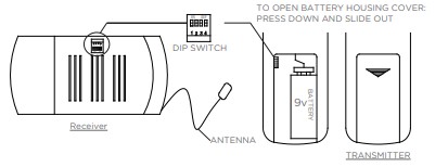
Remote and Receiver PairingCodes are set by pushing the location of the dip switches located on the transmitter and receiver up or down. It is important that the code used for both the remote and receiver are identical for the two devices to be able to communicate; otherwise the remote will not be able to control the fan.
![]() If you plan to install more than one fan then each fan will require the remote and receiver touse a unique code, or else one remote will be able to control more than one fan.
If you plan to install more than one fan then each fan will require the remote and receiver touse a unique code, or else one remote will be able to control more than one fan.
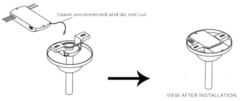
 Installing Receiver Assembly Once the connection has been made, the receiver inserts into the drop rod hanging bracket. The canopy comes up to cover the receiver and bracket.
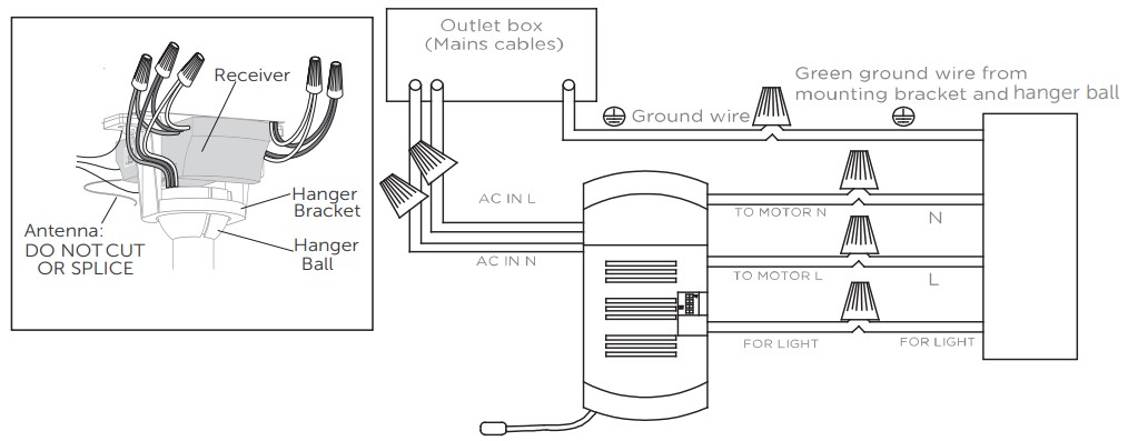
Between fan and receiver:
- Connect the black wire marked “L” from the fan to the black wire marked “TO MOTOR L” from the receiver.
- Connect the blue wire marked “FOR LIGHT” from the fan to the blue wire marked “FOR LIGHT” from the receiver.
- Connect the white wire marked ” N” from the fan to the white wire marked “TO MOTOR N” from the receiverBetween receiver and mains:
- Connect the black live wire marked “AC IN L” from the receiver to the live wire (typically black) from the outlet box.
- Connect the white neutral wire marked “AC IN N” from the receiver to the neutral wire (typically white) from the outlet box.
- Connect the green ground wire marked from the mounting bracket and hanger ball to the ground wire (bare or green) from the outlet box.
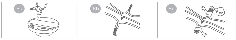
- When wires are matched up, connect them by twisting frayed ends together (see Fig. 8a).
- Screw wire connectors (3 are provided) onto the tops of the twisted wires (see Fig. 8b).
- Fasten them with electrical tape (see Fig. 8c).
![]() WARNING: Be sure no bare wire or wire strands are visible after making connections. Place green and white connections on the opposite sides of box from the black and blue (if applicable) connections.
WARNING: Be sure no bare wire or wire strands are visible after making connections. Place green and white connections on the opposite sides of box from the black and blue (if applicable) connections.
5. Attach the assembly to the mounting bracket
- Unhook the assembly from the mounting bracket.
- Hold the assembly by the canopy and raise up to align the two holes in the canopy with the holes in the mounting bracket.
- Tighten the loosened screws. Now re-secure the screws and washers which were removed(see Fig. 9).

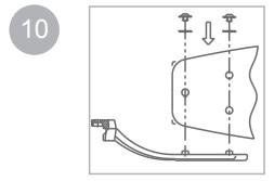
6. Blade and blade bracketUsing the fan blade screws and washers, attach the fan blades . (see Fig.10)Note: This ceiling fan includes 5 dual-finished blades. Depending on personal preference, choose the side that best suits the decor or furniture of your room.
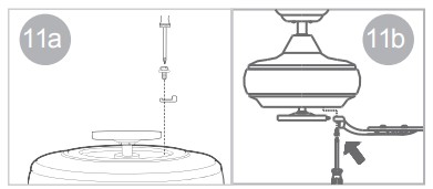
- If there are plastic tabs shaped like bottle caps, remove and discard them. These are stabilizers that protect the motor during shipping. (see Fig. 11a).
- Remove blade bracket screws on the bottom of the motor and use them to attach the blade assembly to the motor. Ensure the screws are tightened (see Fig. 11b).
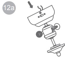
- Remove and retain 3 screws from switch housing. Remove plastic button in center of switch housing cap. Thread light kit assembly onto switch housing cap. Tighten securely with lock washer and hex nut. (see Fig. 12a).
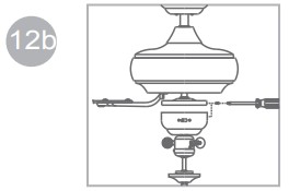
- Connect the wire inside the switch housing cap by snapping the male and female connectors together. Match white wires together and blue wire to black wire together. Screw on light kit assembly and switch housing with 3 screws previously removed. (see Fig. 12b)
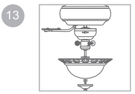
- Install 2X7W LED bulbs (included). Install light kit glass to the light kit assembly with a rubber washer, flat washer, and hex nut. DO NOT overtighten. Install cap and screw finial onto the light kit assembly. (see Fig. 13).
IMPORTANT NOTE: To be compliant with mandatory energy-saving regulations, your fan has a built-in wattage limiter. The limiter limits the wattage of the light kit to 70 Watts. If you replace bulbs that exceed 70 Watts, then your light will not work. To prevent this, ensure bulbs’ wattage is always less than 70 Watts.
OPERATION
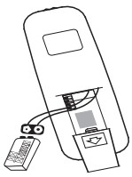
Install the 9V battery (included). To prevent damage to the transmitter remove the battery if not used for long periods.
Restore power to ceiling fan and test for proper operation. The fan remote control controls the fan setting: OFF: Turn off the ceiling fan.HI: Turn on the fan at high speed.MED: Turn on the fan at medium speed.LOW: Turn on the fan at low speed.LIGHT: ON/OFF: Press and release immediately to turn on or off the light.DIMMER: Press and hold to dim or brighten lights to the desired level and release.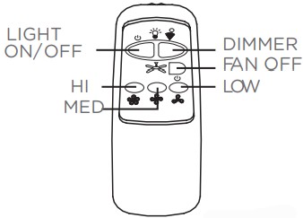 Forward and reverse direction functionThis ceiling fan is equipped with a reverse switch for downward or upward airflow. Eia
![]() NOTE: Do not change the direction of rotation while the fan blades are in motion.To change direction, turn off the fan and wait for the blades to stop rotating before setting the switch to the desired rotation direction, either forward or reverse.
NOTE: Do not change the direction of rotation while the fan blades are in motion.To change direction, turn off the fan and wait for the blades to stop rotating before setting the switch to the desired rotation direction, either forward or reverse.

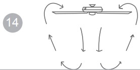
Forward functionOn this setting, the fan will turn counter-clockwise to create a cooling effect. Use this function during warmer weather to circulate the hot air away from your living space (see Fig.14).
 Reverse function
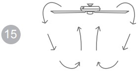
In this setting, the fan will turn clockwise. Use this function during cooler weather to re-circulate warm air (see Fig.15).
MAINTENANCE
- Because of the fan’s natural movement, some connections may become loose. Check the support connections, brackets, and blade attachments twice a year. Make sure they are secure.
- There is no need to oil your fan. The motor has permanently lubricated bearings.
CARE AND CLEANING
- Dust your fan periodically with a soft,dry cloth. Do not use harsh cleaners or materials as they maydamage the unit.
- To prevent bending the blades during cleaning, support the blades so that no pressure is applied tothem.
![]() Caution!Do not allow water to come in contact with fan blades or the ceiling fan. Doing so will create fire and/or shock hazards, damaging property.
Caution!Do not allow water to come in contact with fan blades or the ceiling fan. Doing so will create fire and/or shock hazards, damaging property.
TROUBLESHOOTING
If problems persist, seek help from a certified electrician.
| Problem | Possible reason | Solution |
| Fan is noisy during operation |
|
|
| Fan does not start |
|
Check main fuse and branch circuit breaker. Repair as necessary.
.Check all the wire connections to fan and housing wiring. Repair as necessary.Caution! Make sure the main power is turend of . |
| Light does not work |
|
Ensure the Wire connector in switch housing is connected.Unscrew light bulbs and discard properly, insert new bulb(s |
| Fan does not seem to move much air
|
|
Counter-clockwise (forward) is recommended in warm weather. Turn off fan and power and wait for rotation to stop. Change the forward/ reverse slide switch.. Place fan in the centre of the room so there is at least 12″ (30cm) between the end of the blades and walls or other obstructions. |
| Fan wobbles or shakes excessively
|
|
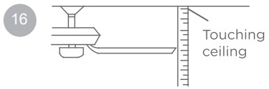
• Make sure that screws that attach fan blade clips to the motor are fastened and tightened.• Tighten screws of fan blade to blade clip securely.• Ensure that canopy and mounting bracket are tightened securely to ceiling joist.• Check by selecting a point on the ceiling above the tip of one of the blades. Measure this distance and ensure all blades are even (see Fig.16). If all blade levels are not equal, adjust accordingly (See Balancing Kit Manual). |
ENVIRONMENTAL PROTECTION
 Used electrical appliances are recyclable and should not be discarded in your regular domestic waste! Please actively support us in conserving resources and protecting the environment by returning this appliance to a collection center (if available).Batteries must be recycled or disposed of properly. Dispose of as per the requirements of your local municipality.
WARRANTY
This For Living product carries a limited ten (10) year warranty against defects in the motor, and a one (1)year warranty against defects in workmanship and materials. Trileaf Distribution agrees to replace the defective product free of charge within the stated warranty period when returned by the original purchaser with proof of purchase. This product is not guaranteed against wear or breakage due to misuse and/or abuse.Subject to the conditions and limitations described below, this product, if returned to us with proof of purchase within the stated warranty period and if covered under this warranty, will be repaired or replaced (with the same model, or one of equal value or specification), at our option. We will bear the cost of any repair or replacement and any costs of labor relating thereto.
These warranties are subject to the following conditions and limitations:a) A bill of sale verifying the purchase and purchase date must be provided;b) This warranty will not apply to any product or part thereof which is worn or broken or which has become inoperative due to abuse, misuse, accidental damage, neglect or lack of proper installation, operation or maintenance (as outlined in the applicable owner’s manual or operating instructions) or which is being used for industrial, professional, commercial or rental purposes;c) This warranty will not apply to normal wear and tear or to expendable parts or accessories that may be supplied with the product that are expected to become inoperative or unusable after a reasonable period of use;d) This warranty will not apply to routine maintenance and consumable items such as, but not limitedto, blades, tune-ups or adjustments;e) This warranty will not apply where damage is caused by repairs made or attempted by others (i.e. persons not authorized by the manufacturer);f) This warranty will not apply to any product that was sold to the original purchaser as a reconditioned or refurbished product (unless otherwise specified in writing);g) This warranty will not apply to any product or part thereof if any part from another manufacturer is installed therein or any repairs or alterations have been made or attempted by unauthorized persons;h) This warranty will not apply to normal deterioration of the exterior finish, such as, but not limited to, scratches, dents, paint chips, or to any corrosion or discoloring by heat, abrasive and chemical cleaners; andi) This warranty will not apply to component parts sold by and identified as the product of anotherthe company, which shall be covered under the product manufacturer’s warranty, if any.Additional LimitationsThis warranty applies only to the original purchaser and may not be transferred. Neither the retailer nor the manufacturer shall be liable for any other expense, loss or damage, including, without limitation, any indirect, incidental, consequential or exemplary damages arising in connection with the sale, use or inability to use this product.Notice to ConsumerThis warranty gives you specific legal rights, and you may have other rights, which may vary from province to province. The provisions contained in this warranty are not intended to limit, modify, take away from, disclaim or exclude any statutory warranties set forth in any applicable provincial or federal legislation.Made in China.Imported by/Trileaf Distribution Trifeuil Toronto, Canada M4S 2B8
[xyz-ips snippet=”download-snippet”]