![]()
ZIF5031Interface for Underfloor HeatingZ-Wave DIN-rail module Type ZIF5031Installation Guide and User’s Manual
![]()
Logic Group A/SVallensbækvej 22 BDK-2605 Brøndby+45 7060 2080[email protected]www.logic-group.com
Product description
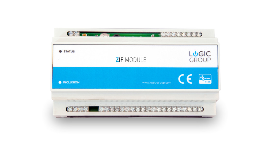
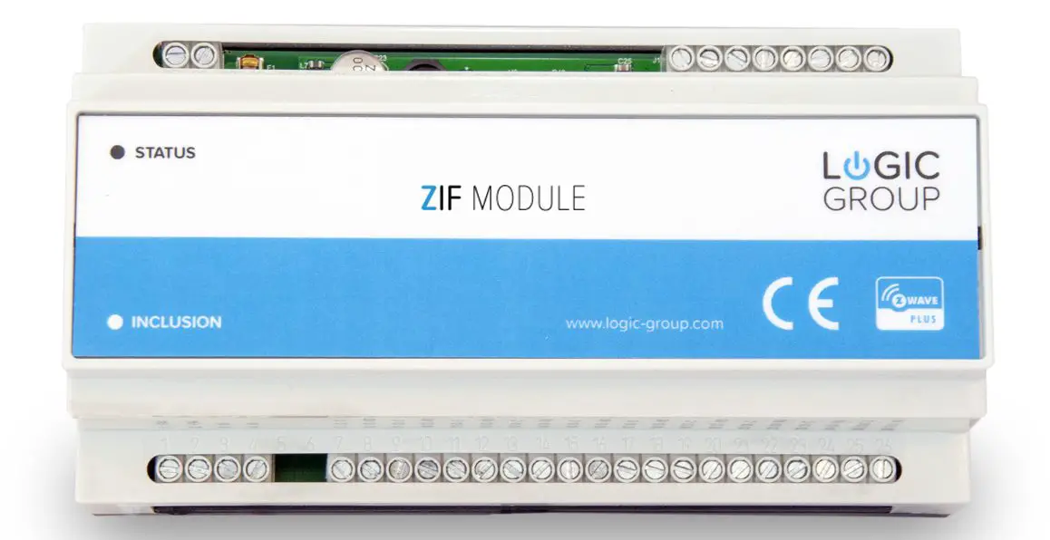
ZIF5031 Z-Wave DIN rail module is a module that clips right onto a DIN rail to add a variety of functions to your wireless Z-Wave network.ZIF5031 is equipped with 10 relay outputs and 4 analog inputs, and a Z-Wave radio for interfacing to the wireless Z-Wave network. The module can be power supplied from a 230V AC mains connection and is able to deliver an output supply of 24V DC.ZIF5031 relay outputs can be freely controlled from the Z-Wave network and used for several purposes, e.g., on/off control of light, control of valve actuators for an underfloor heating system, or control of other home automation systems.ZIF5031 inputs are analog inputs for interfacing simple temperature sensors; NTC, PT1000, etc.It is possible to configure the level- and the indication of the status indicator LED in the front of the ZIF5031 module.
Installation guidelines
ATTENTION: only authorized technicians under consideration of the country-specific installation guidelines/norms may do works with 230 Volt mains power. Prior to the assembly of the product, the voltage network has to be switched off and ensured against re-switching.Use the following procedure to install ZIF5031:
- Use a flat object (such as a flat-head screwdriver) to pull the DIN rail release tab downward.
- Place the top of the ZIF5031 rail mount over the top of the DIN rail.
- Tilt the bottom of the ZIF5031 toward the DIN rail until it snaps into place.
NOTE: When mounting DIN rail products, use a flat-head screwdriver to pull the DIN rail release tab while snapping the device onto the DIN rail.Make any necessary connections to the device, and apply power after all connections have been made.
Preparing and Connecting Wires
When making connections, strip the ends of the wires approximately 6 mm. Use care to avoid nicking the conductors. Tighten the connector to 0.5 Nm. The wire gauge should be 12 to 30 AWG.
Connections
In the drawing below is the different module connections shown.
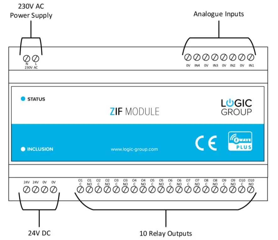
230V AC Power SupplyTerminals for connecting the 230V AC mains power supply. The module has an internal fuse that can be replaced by opening the cover of the module, please see the Technical Specification section for which type of fuses can be used.Analog InputsTerminals for the 4 analog inputs.24V DC Supply OutputsTerminals for the 24V DC power supply output that can be used to be switched through the relay outputs.Relay OutputsTerminals for the 10 relay outputs, with 2 screw terminals for each output, a Common and Normally Open terminal.
Inputs
The inputs of ZIF5031 is analog temperature inputs and the type of the connected thermistor can be selected by means of a configuration parameter for each of the inputs. See configuration parameters 3, 4, 5 and 6. When these parameters are supplied in the configuration parameters for the input, then the input will be able to be used as a temperature measuring input, and the sensor devices in ZIF5031 will be able to report the temperatures as Multilevel Sensor values.NB! The inputs are per default not configured to any type of thermistor, so in order to make an input able to report temperature measuring it must be configured to the appropriate thermistor type. See configuration parameters 3, 4, 5 and 6.
Relay Outputs
ZIF5031 relay outputs are Normally-Open relay contact outputs, that can be used to switch the supply voltage to different kinds of loads, see the technical specification for types of supported loads.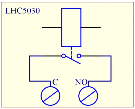 Above schematic outlines how the relay outputs are implemented internally.
24V DC Output
ZIF5031 is supplied with a 24V DC output (looped) that can be used for supplying power to the loads that can be connected to relay outputs. The supply can, for example, be used for powering 24V valve actuators. See the section with technical specifications for the performance of the 24V power supply.
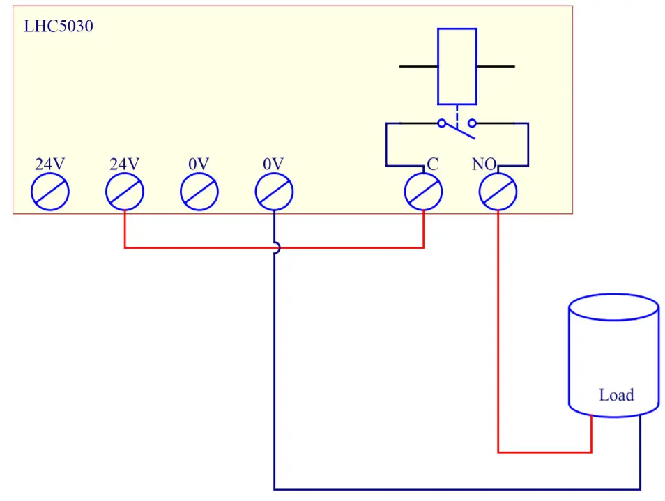 Above schematic outlines an example of how the 24V supply output, together with a relay output, can be used to control a load.
Behavior within the Z-Wave Network
This product can be operated in any Z-Wave network with other Z-Wave certified devices from other manufacturers. All non-battery-operated nodes within the network will act as repeaters regardless of vendor to increase the reliability of the network.On delivery, the device does not belong to any Z-Wave network. The device needs to be added to an existing wireless network to communicate with the devices of this network. Devices can also be removed from a network. Both add and remove processes are initiated by the primary controller of the Z-Wave network. This controller will be turned into a mode for adding or removing devices. Please refer to your primary controller’s manual on how to turn your controller in to add or remove mode. Only if the primary controller is in add or removes mode, this device can be added or removed from the network. When the device is removed from the network, it will set the device back to factory default.If the device already belongs to a network, follow the removal process before adding it in your network. Otherwise, the addition of this device will fail. Place your primary controller in Adding Mode by following the manufacturer’s instructions, then activate the add mode on the device by clicking the small button through the little hole, marked with the text “INCLUSION”, in front of the ZIF5031 module. The Adding Mode is indicated by the ZIF5031 status LED is blinking until a timeout occurs after 10 seconds or if the module has been added to the Z-Wave network.The device is removed in the same manner when the controller is put into Removing Mode.
Factory Reset
ZIF5031 can be factory reset by pressing the small button through the little hole, marked with the text “INCLUSION”, in front of the ZIF5031 module for at least 10 seconds.NOTE: Only use this procedure when the primary network controller is missing or is otherwise inoperable.
Association groups
From a Controller’s point of view, ZIF5031 will consist of a root device and 14 endpoint devices – if the Controller is supporting Multichannel devices, otherwise is only the root device seen by the Controller (endpoint 0).The devices are:
- Root device; an intersection of all the devices (endpoint 0).
- 10 switch devices to control each of the relay outputs (endpoint 1 – 10).
- 4 sensor devices represent the analog inputs (endpoint 11 – 14).
Below is an overview of all the devices and the associated groups for each device.The first number in the association group number indicates the group number for the actual device, and the second number is the group number on the root device (endpoint 0).
| Device 1 (endpoint 1) | Relay output 1 |
| Group 1 / 1 | Lifeline.Sends Device Reset notifications and Basic Report On / Off when relay output 1 is activated.Max. nodes in the group: 5 |
| Device 2 (endpoint 2) | Relay output 2 |
| Group 1 / – | Lifeline.Sends Basic Report On / Off when relay output 2 is activated.Max. nodes in the group: 5 |
| Device 3 (endpoint 3) | Relay output 3 |
| Group 1 / – | Lifeline.Sends Basic Report On / Off when relay output 3 is activated.Max. nodes in the group: 5 |
| Device 4 (endpoint 4) | Relay output 4 |
| Group 1 / – | Lifeline.Sends Basic Report On / Off when relay output 4 is activated.Max. nodes in the group: 5 |
| Device 5 (endpoint 5} | Relay output 5 |
| Group 1 / – | Lifeline.Sends Basic Report On / Off when relay output 5 is activated.Max. nodes in the group: 5 |
| Device 6 (endpoint 6) | Relay output 6 |
| Group 1 / – | Lifeline.Sends Basic Report On / Off when relay output 6 is activated.Max. nodes in the group: 5 |
| Device 7 (endpoint 7) | Relay output 7 |
| Group 1 / – | Lifeline.Sends Basic Report On / Off when relay output 7 is activated.Max. nodes in the group: 5 |
| Device 8 (endpoint 8) | Relay output 8 |
| Group 1 / – | Lifeline.Sends Basic Report On / Off when relay output 8 is activated.Max. nodes in the group: 5 |
| Device 9 (endpoint 9) | Relay output 9 |
| Group 1 / – | Lifeline.Sends Basic Report On / Off when relay output 9 is activated.Max. nodes in the group: 5 |
| Device 10 (endpoint 10) | Relay output 10 |
| Group 1 / – | Lifeline.Sends Basic Report On / Off when relay output 10 is activated.Max. nodes in the group: 5 |
| Device 11 (endpoint 11) | Analog input 1 |
| Group 1 / – | Lifeline.NOP.Max. nodes in the group: 5 |
| Group 1 / – | Sends Multilevel Sensor Reports for input 1.Max. nodes in the group: 5 |
| Device 12 (endpoint 12) | Analogue input 2 |
| Group 1 / – | Lifeline.NOPMax. nodes in the group: 5 |
| Group 2 / 3 | Sends Multilevel Sensor Reports for input 2.Max. nodes in the group: 5 |
| Device 13 (endpoint 13) | Analog input 3 |
| Group 1 / – | Lifeline.NOP.Max. nodes in the group: 5 |
| Group 2 / 4 | Sends Multilevel Sensor Reports for input 3.Max. nodes in the group: 5 |
| Device 14 (endpoint 14) | Analog input 4 |
| Group 1 / – | Lifeline.NOPMax. nodes in the group: 5 |
| Group 2 / 5 | Sends Multilevel Sensor Reports for input 4.Max. nodes in the group: 5 |
Configuration parameters
Z-Wave products are supposed to work out of the box after they are added to the Z-Wave network, however, certain configurations of a device can alter the functionality to better serve the needs of the users or unlock further enhanced features.Parameter 1, Parameter size 1 byte. Status LED.Configuration of the status LED.
| Value | Description |
| 0 | LED turned off. |
| 1 | LED turned on. (Default) |
| 2 | LED flashing at 1-second intervals (½ Hz). |
| 3 | LED flashing at ½ second interval (1 Hz). |
Parameter 2, Parameter size 1 byte. Status LED brightness level.Configure the percentage of light in the status LED, when the LED is turned on
| Value | Description |
| 0 | 100 Specifies the brightness level of the LED when it is on. Default is 50. |
Parameter 3, Parameter size 1 byte. Thermistor type connected to input 1.This parameter decides which kind of thermistor that is connected to the input.
| Value | Description |
| 0 | No thermistor, input is disabled. (Default) |
| 1 | 10K NTC. (PART NUMBER: TT02-10KC3-93D-3000R-TPH) |
Parameter 4, Parameter size 1 byte. Thermistor type connected to input 2.This parameter decides which kind of thermistor that is connected to the input.
| Value | Description |
| 0 | No thermistor, input is disabled. (Default) |
| 1 | 10K NTC. (PART NUMBER: TT02-10KC3-93D-3000R-TPH) |
Parameter 5, Parameter size 1 byte. Thermistor type connected to input 3.This parameter decides which kind of thermistor that is connected to the input.
| Value | Description |
| 0 | No thermistor, input is disabled. (Default) |
| 1 | 10K NTC. (PART NUMBER: TT02-10KC3-93D-3000R-TPH) |
Parameter 6, Parameter size 1 byte. Thermistor type connected to input 4.This parameter decides which kind of thermistor that is connected to the input.
| Value | Description |
| 0 | No thermistor, input is disabled. (Default) |
| 1 | 10K NTC. (PART NUMBER: TT02-10KC3-93D-3000R-TPH) |
Parameter Number 7, Parameter Size 1. Input 1 calibration.
| Value | Description |
| -40 – 40 | -4.0°C – 4.0°C. Default is 0 (0.0°C). |
Parameter Number 8, Parameter Size 1. Input 2 calibration.
| Value | Description |
| -40 – 40 | -4.0°C – 4.0°C. Default is 0 (0.0°C). |
Parameter Number 9, Parameter Size 1. Input 3 calibration.
| Value | Description |
| -40 – 40 | -4.0°C – 4.0°C. Default is 0 (0.0°C). |
Parameter Number 10, Parameter Size 1. Input 4 calibration.
| Value | Description |
| -40 – 40 | -4.0°C – 4.0°C. Default is 0 (0.0°C). |
Parameter Number 11, Parameter Size 2. Input 1 report interval.Time interval between consecutive temperature reports. Temperature reports can be also sent as a result of polling.
| Value | Description |
| 0 | Reporting of temperatures disabled. |
| 1 – 8640 | Multiply with 10 seconds, 10 seconds – 24 hours. Default is 6 (60 seconds). |
Parameter Number 12, Parameter Size 2. Input 2 report interval.Time interval between consecutive temperature reports. Temperature reports can be also sent as a result of polling.
| Value | Description |
| 0 | Reporting of temperatures disabled. |
| 1 – 8640 | Multiply with 10 seconds, 10 seconds – 24 hours. Default is 6 (60 seconds). |
Parameter Number 13, Parameter Size 2. Input 3 report interval.Time interval between consecutive temperature reports. Temperature reports can be also sent as a result of polling.
| Value | Description |
| 0 | Reporting of temperatures disabled. |
| 1 – 8640 | Multiply with 10 seconds, 10 seconds – 24 hours. Default is 6 (60 seconds). |
Parameter Number 14, Parameter Size 2. Input 4 report interval.Time interval between consecutive temperature reports. Temperature reports can be also sent as a result of polling.
| Value | Description |
| 0 | Reporting of temperatures disabled. |
| 1 – 8640 | Multiply with 10 seconds, 10 seconds – 24 hours. Default is 6 (60 seconds). |
Command Classes
 report this ad
Supported Command Classes.
- Association (version 2)
- Association Group Information (version 1)
- Multi Channel Association (version 3)
- Version (version 2)
- Configuration (version 3)
- Manufacturer Specific (version 2)
- Z-Wave Plus Information (version 2)
- Device Reset Locally (version 1)
- Security (version 2)
- Powerlevel (version 1)
- Firmware Update (version 4)
- Multi Channel (version 4)
- Basic (version 2)
- Supervision (version 1)
- Multilevel Sensor (version 5)Controlled Command Classes
- Multilevel Sensor (version 5)
Technical Specifications
| Power supply | 100V-240V AC 50/60Hz |
| Fuse | 3.15A Quick-Acting, UMF 250Schurter Inc., part no.: 3405.0171.11 |
| 24V DC output | Maximum 1.17A, 28W |
| Relay outputs | Rated carry current: 5AMax. switching voltage: 250V AC, 30V DCMax. switching current: 5AMax. load: 5A at 250V AC (1,250W), 5A at 30V DC (150W) |
| 24V DC output | Max. load: 1.1 A (25W) |
| Inputs | Max. input voltage: 10V DCInput impedance: 10K OhmLoop output voltage: 5V DC |
| Connection terminals | Solid wire: 30-12 AWG / 0.05-3.31 mm²Stranded wire: 30-12 AWG / 0.05-3.31 mm²Torque: 4 Lb. In / 0.5 NmWire stripe length: 6 mmScrew: M2.5 |
| Power consumption | 0.6 W standby |
| Radio protocol | Z-Wave®: EU 868.4MHz – 500 Series. |
| Approvals | CEEN 50491-3: 2009EN 60669-2: 2004Z-Wave Plus (pending) |
| Explorer Frame Support | Yes |
| SDK | 6.71.00 |
| Device Type | Slave with routing capabilities |
| Generic Device Class | Binary Switch. |
| Specific Device Class | Valve Open Close |
| Routing | Yes |
| FLiRS | No |
| Z-Wave Plus | Yes |
| Z-Wave Security | S0, S2 Unauthenticated, S2 Authenticated |
| Firmware Version | 0.62 |
References
[xyz-ips snippet=”download-snippet”]