
ATTIC LADDER INSTALLATION INSTRUCTIONS MODELS: S224P, S254P, AS226P, AS256P, AL226P, AL256P, CS224P, CS224I, CS254P, CS254I, CL224P,CL224I, CL254P, CL254I, L224P, L254P, S305P, CS305P, L305P, CL305P, AL228P, AL258P
WARNING
Before you start installing your new Louisville Ceiling Mounted Folding Attic Ladder, you must read and understand the following:
- For residential use only. Not for use in a commercial or industrial setting
- Installation requires two people.
- Check the ceiling height to make sure the ladder length is correct. If the ladder is too short, return it to the point of purchase for an exchange. Under no circumstance is any folding attic ladder to be used when the ceiling–to–floor measurement exceeds the maximum ceiling height as indicated for the Ceiling Mounted Folding Attic Ladder you are installing (See “Max Ceiling Height” column in table 2, page 3).
- This folding attic ladder is completely assembled and is ready for installation. Do not disassemble it to install.
- The springs on this folding attic ladder are under pressure. Do not attempt to remove or replace before installation.
- Prior to installation, verify that all fasteners are properly tightened. Re-check these periodically after initial installation.
- Make sure there is no wiring or piping that the saw or drill can come in contact with during installation.
- Opening or standing on the folding attic ladder’s climbing sections prior to properly fastening to ceiling joists could cause serious bodily injury.
- Verify that the unit meets local building codes and that the intended area of installation is of sufficient strength to be used for a walking or working surface.
- If the home has roof trusses, do not cut the ceiling joists without consulting an engineer for approval.
- Before installation, read all the instruction labels on the folding attic ladder.
- Improper installation could result in serious bodily injury.
- Do not attempt to open the door prior to installation.
- Only use 16d nails or 1/4” x 3” lag screws (not included) for the permanent installation step.
- Follow the “Adjust The Ladder Length” instructions on Step 3 for proper trimming instructions.
- Annually lubricate (spray silicone recommended) pivot points of right and left folding arm mechanism (power arm assembly) to provide smooth, long-lasting operation.
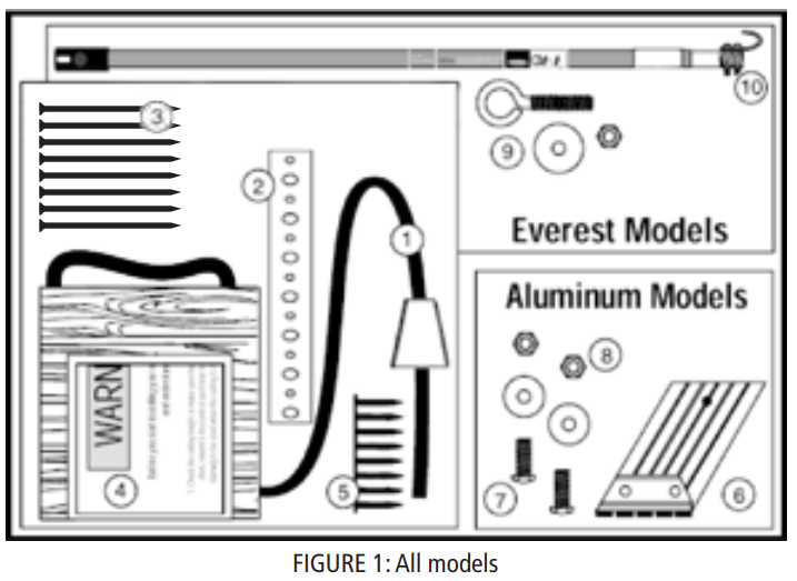
Included with your Folding Attic Ladder
| NO. | ITEM | QTY. |
| 1 | Pull cord — 36″ | 1 |
| 2 | Support Straps | 4 |
| 3 | 16d nails | 8 |
| 4 | Installation Instructions | 1 |
| 5 | Roofing nails — 7/8″ | 8 |
| 6 | **Aluminum feet | 2 |
| 7 | ** 1/4″ Bolts | 2 |
| 8 | ** 1/4″ Locknuts & washers | 2 |
| 9 | +Eyebolt. nut & washer | 1 |
| 10 | +Pole hook | 1 |
| ‘Aluminum models I + Everest models |
TABLE 1
ATTIC LADDER SERIES NAME AND MODEL NUMBER CROSS-REFERENCE
WOOD
|
Series |
Models |
|||
| Premium | S224P | S254P | L224P | L254P |
| Champion | CS224P | CS254P | CL224P | CL254P |
| CS2241 | CS2541 | CL2241 | CL2541 | |
| Big Boy | S305P | CS305P | L305P | CL305P |
|
ALUMINUM |
||||
| Series | ||||
| Summit | AS226P | AS256P | AL226P | AL256P |
| Everest | AL228P | AL258P |
|
MATERIALS REQUIRED |
| [1.] Stepladder [2.] Hammer 13.1 Adjustable wrench [4.] Tape measure [5.] Hand saw [6.] Hack saw [7.] Drill [8.] Drill bit 3/16″,1/4″ [9.] Phillips screwdriver [10.] (12) IA” x 3″ lag screws or 16d nails [11]. Shims |
Installation instructions for wood models and for aluminum models
Read instructions and warnings completely before startingIMPORTANT: DO NOT OPEN FOLDING ATTIC LADDER UNTIL INSTRUCTED TO IN STEP NUMBER 3.
Folding Attic Ladder Location:Allow ample room for the swing clearance and the landing space of the folding attic ladder when it is opened (see figure 2 and table 2). Locate the folding attic ladder rough opening so that when you enter the storage area, you will have adequate head clearance.
You must have a rough opening as shown for your model in table 2. If not, proceed to the appendix for framing instructions.

| MODEL | ROUGHOPENING | MAX. CEILING HT. “A” | LANDING SPACE* “B”
|
SWING CLEARANCE “C” |
| S224P, AS226P, CS224P, CS224l | 22 /2“ x 54″ | 8′ 9″ | 63″ | 66″ |
| S254P,AS256P, CS254P, CS254I | 25 1/2″ x 54″ | 8′ 9″ | 63″ | 66″ |
| L224P, AL226P, CL224P, CL224l | 22 1/2″ x 54″ | 10′ | 71″ | 75″ |
| L254P, AL256P, CL254P, CL254I | 25 1/2″ x 54″ | 10′ | 71″ | 75″ |
| S305P | 30″ x 60″ | 8′ 9″ | 63″ | 66″ |
| CS305P | 30″ x 54″ | 8′ 9″ | 60″ | 69″ |
| L305P | 30″ x 60″ | 10′ | 71″ | 75″ |
| CL305P | 30″ x 54″ | 10′ 1″ | 67″ | 79″ |
| AL228P | 22 1/2″ x 63″ | 12′ | 85″ | 87″ |
| AL258P | 25 1/2″ x 63″ | 12′ | 85″ | 87″ |
|
*When installed at maximum ceiling height |
TABLE 2
STEP 1: PRELIMINARY INSTALLATION INSTRUCTIONSA. Attach four E–Z Hang temporary support straps to the frame. Refer to figure 3 and the instructions listed below.
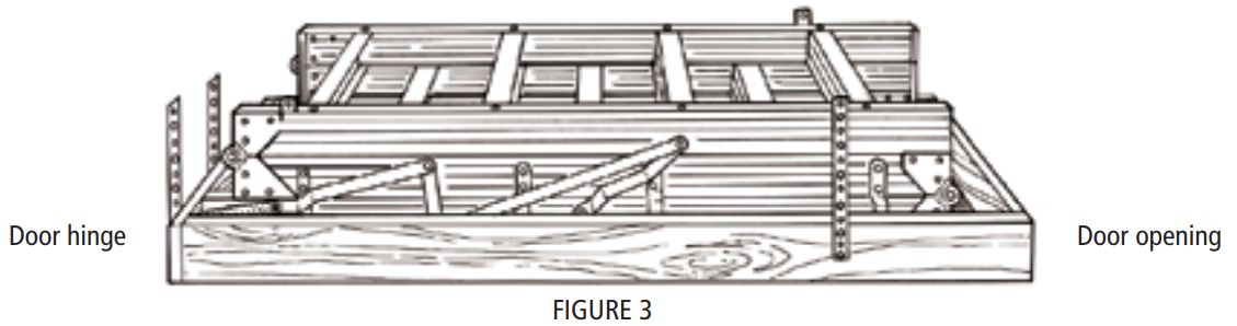
- Place the folding attic ladder on the floor with the door opening on your right–hand side.
- Using the roofing nails and straps provided, attach one strap using two nails on the outside of the attic ladder frame at the extreme right-hand corner near the doorstop block.
- Attach the second strap opposite the first strap on the far outside frame.
- The third and fourth straps should be positioned on the door hinge side near each corner opposite the door opening.
B. Position one person up in the attic, and position one person in the room below. When using a step ladder make sure the ladder is fully open, all feet firmly supported and the user’s weight and materials do not exceed the load rating of the ladder.
C. The person in the room below will need to raise the attic ladder into the rough opening and position the attic ladder’s door frame flush with the ceiling surface.
D. The person in the attic should then bend the metal E–Z Hang strapping at the four corners of the attic ladder frame over the adjoining ceiling joists and nail through the metal strapping using four of the 16d nails provided to temporarily suspend the attic ladder.
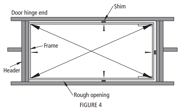
CAUTION: This is only a temporary connection, NEVER climb on the ladder in this condition.E. Carefully open the attic ladder door but do not unfold the climbing section until indicated in step 3. Place the frame on the door hinge side of the ladder up against the header and center side to side in the rough opening. Temporarily secure to header with 16d nail. Make sure the frame is flush with the ceiling before nailing (figure 4, next page).
F. Center and square the opposite side of attic ladder frame using shims. Ensure ladder frame is square by measuring diagonals of the frame within 1/8”. Secure other sides ofladder frame to ceiling joists with remaining three 16d nails (figure 4).
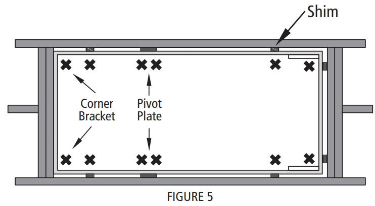
STEP 2: PERMANENT INSTALLATIONA. Install fasteners at the 12 locations shown in figure 5 for permanent installation. Either 1/4” x 3” lag screws or 16d nails should be used. Install shims when necessary to fill any gaps between the door frame and rough opening. Make sure to install the fasteners in the holes provided in the corner brackets and pivot plates.
NOTE: When using lag screws first drill 1/4” diameter holes through the frame at each location to prevent splitting and follow with 3/16” pilot holes in the ceiling joist to facilitate installation of the lag screw.
B. WARNING: Never use deck or sheetrock screws for permanent installation.
STEP 3: ADJUST LADDER LENGTH
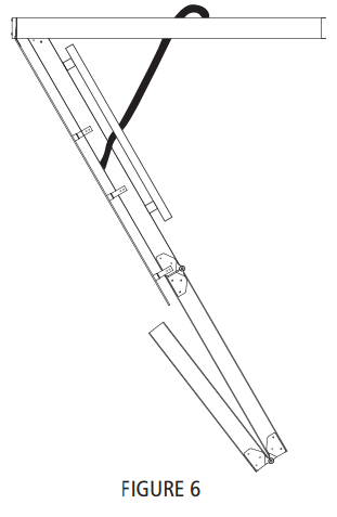
A. Carefully unfold ladder to the ground rotating bottom section behind middle section (figure 6). Press down on the top and middle sections of the ladder to ensure the power arms are fully extended before taking measurements for trimming your ladder.
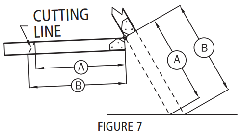
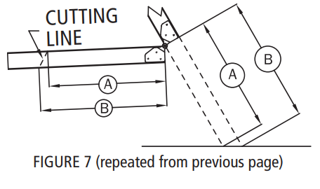
B. With a straight edge, measure distances from the middle section to floor, for both A & B lengths (figure 7).
WOOD MODELS: Proceed to “C” ALUMINUM MODELS: Skip to page 7 “Additional steps for aluminum models only”
C. Record A & B values in table 3 for both rails.
|
LEFT RAIL |
RIGHT RAIL |
||
|
A |
B |
A |
B |
| Measurement to floor |
TABLE 3 (Wood models only)
D. Transfer these dimensions to the bottom section of the ladder right and left rails and draw a cutting line between the two points. Trim bottom section to length using a wood saw (figure 7).Proceed to “Check the length after making your cuts” on page 8…
ADDITIONAL STEPS FOR ALUMINUM MODELS ONLY:
A. For aluminum models, complete table 4. Subtract 3/4” from each measurement and record the results in row titled “Rail cut length”.
| LEFT RAIL | RIGHT RAIL | |||
| A | B | A | B | |
| Measurement to floor | ||||
| Subtract for shoe | (-3/4“) | (-3/4″) | (-3/4″) | (-3/4″) |
| Rail cut length |
TABLE 4 (Aluminum models only)
B. Transfer cut length dimensions from table 4 to the bottom section of the ladder right and left rails and draw a cutting line between the two points. Trim bottom section to length using a metal cutting saw (figure 7).
C. Rotate the bottom section back in line with top sections and press down on the middle section to ensure that the power arms are fully extended.
D. Slide aluminum foot over ladder rail. Position the foot so that the extended sections remain straight and the foot is in full contact with the floor. Drill 1/4” hole through the rail using the hole provided on the foot as a template. Anchor securely with 3/4” bolts and locknuts provided.
CHECK THE LENGTH AFTER MAKING YOUR CUTS
Again, be sure the attic ladder power arms are fully extended. Trimmed correctly, your attic ladder should look like figure 9.Verify that there are no gaps in the section and both feet are flat on the floor.

If the attic ladder looks like figure 10, then both of the legs are too long and need to be trimmed further.If the attic ladder looks like figure 8, then both of the legs are too short, and the attic ladder is not safe to use. A new lower section would need to be purchased from the manufacturer.
ADJUSTING THE SPRING TENSION (IF NEEDED) [CS305P & CL305P models only]Your attic ladder is equipped with a unique and easy way to adjust the tension on each of the two springs. With the attic ladder in the closed position, use an adjustable or 7/16” wrench and tighten (turn clockwise) the red kep nut on the J-bolts that attach the springs to the door panel. Alternate the tightening of each spring to raise the door panel evenly so it ends up flush with the ceiling.
INSTALLING HARDWARE
A. Ladders with pull cord and pendant.
- Thread pull the cord through the pre-drilled hole in the door and tie a knot in the end of the cord.
- Be sure the knot is large enough to not slip through the hole.
B. Ladders with eye–bolt and pole hook.
- Slide eye–bolt through the hole in the attic ladder door.
- Install washer onto eye–bolt on the opposite side of the door.
- Securely fasten nut onto the eye–bolt.
TRIM INSTALLATIONTo install trim molding leaves 3/8” clearance between the door panel at the hinge end and 1/8” clearance on the other 3 sides.
EVEREST ALUMINUM 12’ FOLDING ATTIC LADDER OPENING AND CLOSING INSTRUCTIONSClosely follow instructions attached to pole hook when opening and closing Everest Folding Attic ladder.
Required to operate: Two People | Attic ladder Pole hook | Stepladder or Step Stool
Opening Instructions:
- Standing on the floor, reach up with the pole hook and firmly hook the eye–bolt on the attic door, and pull to open door.
- Position a stepladder to the side of the attic ladder’s climbing section drop-down area.DANGER: never place the stepladder or person in the path of the attic ladder’s climbing section drop-down area.
- Position the two people (one on the stepladder and one on the floor) on either side of the attic ladder drop-down area.
- The person on the stepladder should slowly and carefully begin unfolding the two hinged sections of the attic ladder to the person on the floor.
- Continue to unfold the attic ladder until both sections are fully extended. Press downward on the climbing section to ensure the power arm assembly is fully open and in a locked position.
Closing Instructions:
- Position one person on the stepladder and the other on the floor on either side of the attic ladder.
- The person on the floor should begin to fold up the bottom and middle sections, handing them off to the person on the stepladder to complete the folding process.
- Use the pole hook to tap the power arm toward the open end of the attic ladder (away from the door hinge) to release the power arm (See figure 12).
- Hook the eye–bolt on the door with the pole hook and push firmly upward until the springs engage. Slowly control the door with the pole hook until completely closed.
- Remove pole hook and store in a safe place.

APPENDIX – Framing A Rough Opening Parallel To Ceiling Joist
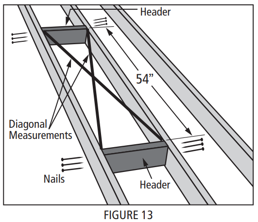
Make a rough opening to the size as required in table 2 (page 3) ensuring that the dimensions of the diagonals of the frame are the same as illustrated in figure 13.
A. For Rough opening without joist removal (figure 13)
- Locate headers in the front and rear of the opening as shown in figure 13.
- Check for squareness by making sure that diagonal measurements are within 1/8”.
- Secure using (3) 16d nails into each end of the Header.
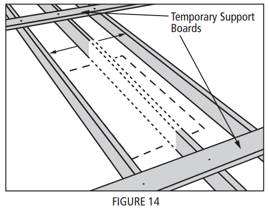
B. Rough opening with joist removal (figure 14)
- Install temporary support boards spanning both sides of joists to be removed.
- Remove joist at length to allow for doubleheaders to be installed on both ends of the opening.
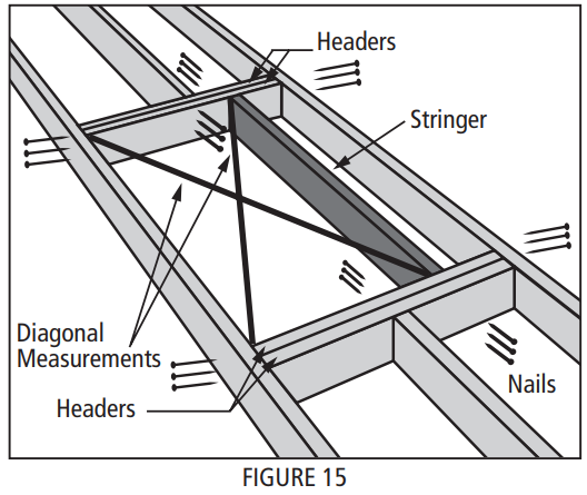
(figure 15)
- Locate doubleheaders at each end of the opening and secure with (3) 16d nails into each end of the headers.
- Install stringer and check for squareness by making sure that diagonals are within 1/8”.
- Secure using (3) 4” nails into each end of the stringer.
CAUTION: Consult an engineer or obtain architectural approval for installations that require the removal of roof trusses or rough openings perpendicular to the ceiling joists.

Customer service: 1–800–666–2811 or email [email protected]
Louisville Ladder Inc.7765 National Turnpike, Unit 190Louisville, KY 402141–(800)–666–2811 (U.S. & CANADA)1–(502)–636–2811 | FAX: 1–(800)–274–4566www.LouisvilleLadder.comSpring-based Attic Ladder Installation Instructions 2014 v1 [F9018]April 2014 | © 2014 Louisville Ladder, Inc. All rights reserved.
References
[xyz-ips snippet=”download-snippet”]