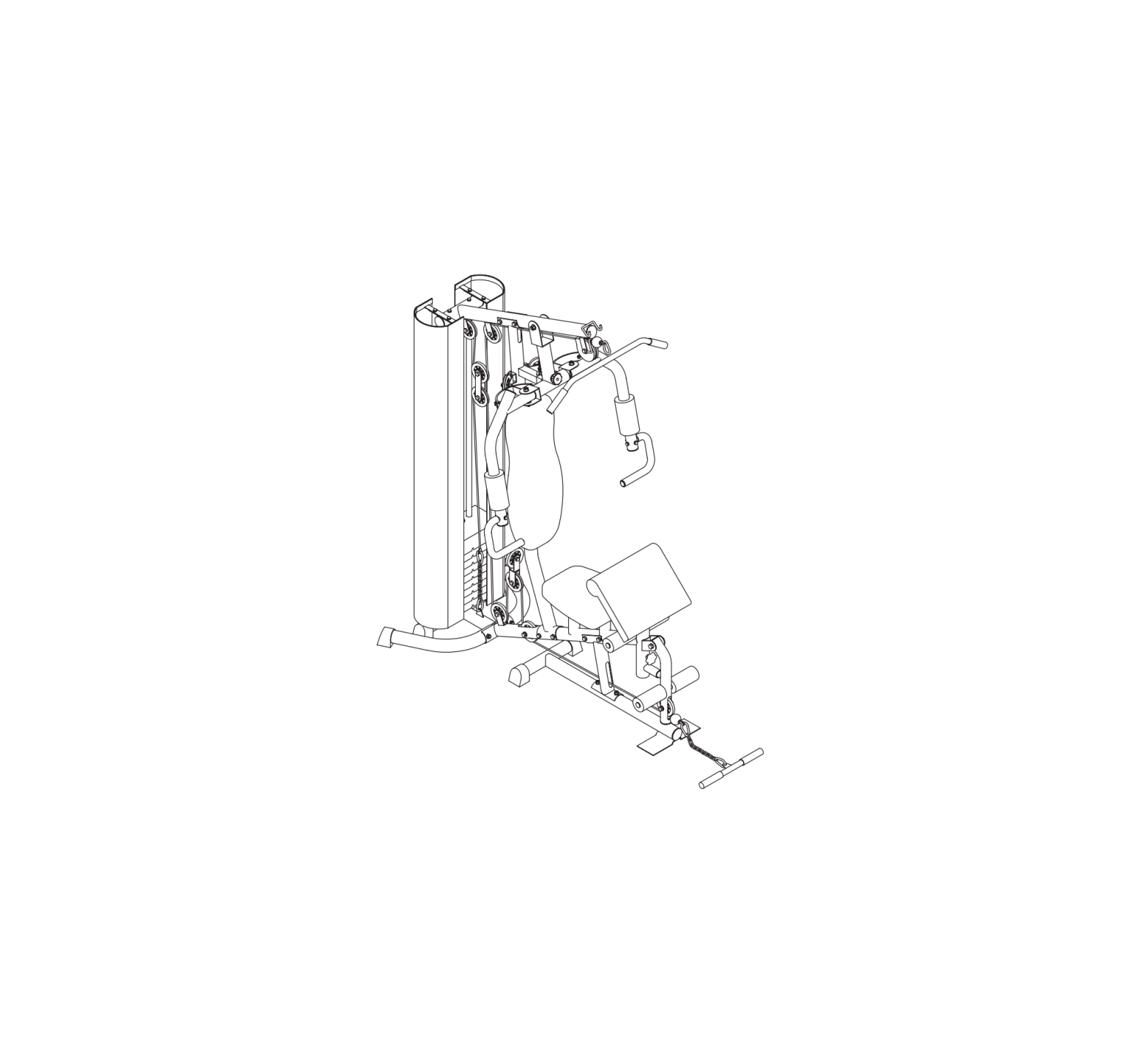
LSG SSN100 All-In-One Single Station Pulley Machine
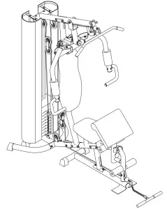
Product may vary slightly from the item pictured due to model upgrades.
 |
Read all instructions carefully before using this product. Retain this owner’s manual for future reference. |
NOTE:This manual may be subject to updates or changes. Up to date manuals are available through our website at www.lsgfitness.com.au
IMPORTANT SAFETY INSTRUCTIONS
| WARNING: Read all instructions before using this machine. |
- Install the product on a flat level surface.
- Place your unit on a solid, level surface when in use.
- Never allow children on or near the machine.
- Keep hands away from all moving parts.
- Never drop or insert any object into any openings.
- Care must be taken when lifting or moving the equipment so as not to injure your back. Always use proper lifting techniques and/or seek assistance if necessary.
- Keep children and pets away from the machine at all times. DO NOT leave children unattended in the same room with the machine.
- Only 1 person at a time should use the machine.
- If the user experiences dizziness, nausea, chest pain, or any other abnormal symptoms, STOP the workout at once. CONSULT A PHYSICIAN IMMEDIATELY
- Do not use the machine near water or outdoors. · Keep hands away from all moving parts.
- Always wear appropriate workout clothing when exercising. DO NOT wear robes or other clothing that could become caught in the machine. Running or aerobic shoes are also required when using the machine.
- Use the machine only for its intended use as described in this manual. DO NOT use attachments not recommended by the manufacturer. · Do not place any sharp objects around the machine.
- Disabled person should not use the machine without a qualified person or physician in attendance.
- Never operate the machine if the machine is not functioning properly.
- A spotter is recommended during exercise.
CARE INSTRUCTIONS
- Lubricate moving joints with silicon spray after periods of usage.
- Be careful not to damage plastic or metal parts of the machine with heavy or sharp objects.
- The machine can be kept clean by wiping it down using dry cloth.
- Check and adjust the tension of wire rope on a regular basis.
- Regularly check all moving parts and make sure there are signs of wear and damage, if any the use of the device must be stopped immediately and contact our after-sales department.
- During inspection, it is necessary to make sure that all bolts and nuts are completely fixed. If any bolt or nut connection is loosened, please re-tighten.
- Check weld for cracks.
- Failure to perform daily maintenance may result in personal injury or equipment damage.
| Caution: Please always check your chain links parts are fully tightened or clipped in properly before use as this may cause injury if the links are not screwed all the way or clipped properly. |
EXPLODED DIAGRAM
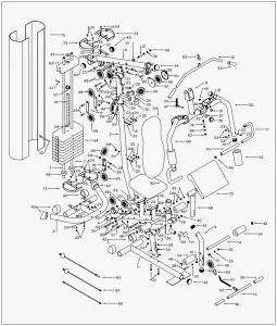
PARTS LIST
| Part No. | Description | Qty |
| 1 | Base Frame | 1 |
| 2 | Seat post | 1 |
| 3 | Rear Stabilizer | 1 |
| 4 | Seat Support Tube | 1 |
| 5 | Upright Support Tube | 1 |
| 6 | Leg Curl Tube | 1 |
| 7 | Guiding Tube | 2 |
| 8 | Bridge Tube | 1 |
| 9 | Pull unit | 1 |
| 10L | Butterfly Arm – Left | 1 |
| 10R | Butterfly Arm – Right | 1 |
| 11 | Handlebar | 2 |
| 12 | Lat Bar | 1 |
| 13 | Lower Pull Bar | 1 |
| 14 | Foam Tube for Leg curl | 2 |
| 15 | Bracket for Seat/Backrest | 2 |
| 16 | Hex Head Bolt M12X108 mml | 2 |
| 17 | Bracket for Pulley | 2 |
| 18 | Two Way Bracket for Pulley | 1 |
| 19 | Select Bar | 1 |
| 20 | Pulley Bracket | 2 |
| 21 | Axle for Pull Unit | 1 |
| 22 | Hex Head Bolt M8 x 20mmL | 10 |
| 23 | Hex Head Bolt M10 x 60mmL | 2 |
| 24 | Hex Head Bolt M8 x 15mmL | 18 |
| 25 | Hex Head Bolt M10 x 40mmL | 9 |
| 26 | Hex Head Bolt M10 x 45mmL | 1 |
| 27 | Hex Head Bolt M10 x 75mmL | 4 |
| 28 | Hex Head Bolt M10 x 70mmL | 1 |
| 29 | Hex Head Bolt M12x 75mmL | 1 |
| 30 | Hex Head Bolt M10 x 80mmL | 7 |
| 31 | Powder Metal Ring φ12 | 4 |
| 31A | Powder Metal Ring φ16 | 2 |
| 32 | Select Pin | 1 |
| 33 | Curve Washer OD22XID8.3 | 10 |
| 34 | Curve Washer OD23XID10.3 | 6 |
| 35 | Flat Washer OD23XID10.3 | 20 |
| 35A | Flat Washer OD23XID8.3 | 20 |
| 36 | Flat Washer OD24XID12.3 | 8 |
| 37 | Flat Washer OD40XID12.5 | 2 |
| 38 | M8 Nylon Nut | 2 |
| 39 | M10 Nylon Nut | 26 |
| 40 | M12 Nylon Nut | 6 |
| 41 | Fixed Pin for Weight Stack | 1 |
| 42 | End Cap | 6 |
| 43 | φ60 Round Cap | 2 |
| 44 | φ60 Flat Cap | 2 |
| 45 | φ50.8 Flat Cap | 8 |
| 46 | φ25.4 Flat Cap | 6 |
| 47 | Pin | 1 |
| 48 | Rubber Ring | 2 |
| 49 | Pulley | 11 |
| 49A | Pulley A | 1 |
| 50 | Cap for Small Pulley | 2 |
| 51 | Plastic Bushing | 4 |
| 52 | Rubber Stopper | 1 |
| 53 | Foam for Butterfly Arm | 2 |
| 54 | Foam for Leg Curl | 4 |
| 55 | Foam for Handlebar | 1 |
| 56 | Hand Grip | 1 |
| 57 | Bushing for Weight Stack | 1 |
| 58 | Round Cap for Select Bar | 1 |
| 59 | Beck cushion | 1 |
| 60 | Seat | 1 |
| 61 | Chain 6 Links | 2 |
| 62 | Hook | 5 |
| 63 | Weight Stack 8 Lbs | 1 |
| 64 | Weight Stack 10 Lbs | 9 |
| 65 | Cable for Lat Bar | 1 |
| 66 | Cable for Butterfly Arm | 1 |
| 67 | Cable for Lower Pull Bar | 1 |
| 68 | Cushion Support tube | 1 |
| 69 | Bushing | 1 |
| 70 | Rubber Stopper | 1 |
| 71 | Knob | 1 |
| 72 | Elbow Cushion | 1 |
| 73 | Bracket for Cloth Cover | 4 |
| 74 | Spring | 1 |
| 75 | Cloth Cover for Left/Right | 2 |
| 76 | Plum-nut | 1 |
ASSEMBLY INSTRUCTIONS
STEP 1
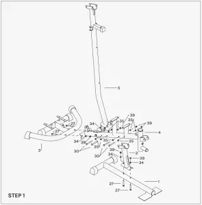
- Attach the Rear Stabilizer (03) to the Seat Support Tabe (04) and tighten by X2 Hex Head Bolt (27), X4 Curve Washer (34) and X2 Nylon Nuts (39).
- Attach the Upright support tube (02) to the Seat Support Tabe (04) and tighten by X2 Hex Head Bolt (30), X4 Flat Washer (35) and X2 Nylon Nuts (39).
- Attach the Base Frame (01) to Upright support tube (02) and tighten by X2 hex Head Bolt (27), X4 Flat Washer (34) and X2 Nylon Nuts (39).
- Attach the Main support tube (05) to the Seat Support Tube (04) and tighten by X2 hex Head Bolt (30), X4 Flat Washer (35) and X2 Nylon Nuts (39).
STEP 2
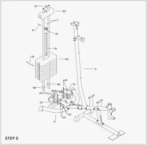
- Attached the Bracket for Cloth Cover L (73) to he Rear stabilizer (03) and tighten by X2 Hex Head Bolt (24), X2 Washer (35A).
- Do the same procedure for the Bracket for Cloth Cover R (73) to the right side of Rear stabilizer (03) by the same parts.
- Slide both Guiding Tube (07) through Rubber Ring (48) into the 2 holes on the Rear Stabilizer (3), tighten from the bottom side by X2 Curve Washer (33) and X2 Hex Head Bolt (22).
- Place the Weight Stack (64) into the Guiding tube (07). (Be careful loading the weights and seek assistance where needed.)
- Place the Bushing for Weight Stack (57) onto the Select Bar (19) and fixed by the Fixed Pin (41). Then place the Weight Stack (63) upper the Select Bar (19) and place the Flat Washer (37) upper the Weight Stack (63).
- Insert the Select Pin (32) through the Weight Stack (64) into the hole of Select Bar (19).
STEP 3
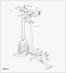
- Place the Guiding Tube (07) into the Bridge Tube (8) and tighten by X2 Flat Washer (33) and X2 Hex Head Bolt (22).
- Attach the Bridge Tube (8) to the Upright Support Tube (05) and tighten by X2 Hex Head Bolt (30), X4 Flat Washer (35) and X2 Nylon Nuts (39).
STEP 4
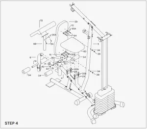
- Attach the Backrest (15) to the Upright support tube (05), tighten by X2 Curve Washer (34) and X2 Nylon Nuts (39) through the thread holes on the Upright support tube (05).
- Attach the Backrest Cushion (59) onto the Upright Support Tube (05) by putting the screw on the Bracket for Backrest (15) into holes on Upright Support Tube (05), tighten by X4 hex Flat washer (35A), X4 Hex held bolt (24).
- Attach the Seat (60) onto the Seat Support Tube (04) by putting the screw on the Bracket for Seat into holes, tighten by X4 hex Flat washer (35A), X4 Hex held bolt (24) .
- Attach the Elbow Cushion (72) onto the Elbow Cushion Support Tube (68) tighten by X4 Washer (35A), X4 Hex held bolt (24) .
- Attach the Elbow Cushion Support Tube(68) into the Seat Support Tube(04), then roll with the Knob(71).
- Screw-in the Small Rubber Stopper (52) into the front side of Seat Support Tube (04).
- Attach the Leg Curve Tube (06) to the front side of Seat Support Tube (04), tighten by X1 Hex Head Bolt (29), X2 Flat Washer (36) and X1 Nylon Nut (40).
- Attach the Foam Tube for Leg Curl (14) into the holes on Leg Curl Tube (06) and front/upper bracket ofSeat Support Tube (04).
- Attach the Foam for Leg Curl Tube (54) onto the 2 sides of each Foam Tube for Leg Curl (14).
STEP 5
- Attach the Pull Unit (09) to the Bridge Tube (08), insert the Axle for Pull Unit (21) through X2 Powder Metal Ring (31A), X2 Flat washer (36), X2 Nylon Nuts (40).
- Attach the Butterfly Arm R (10R) to the right side of Pull Unit (09) through X2 Powder Metal Ring (31) and X2 Flat Washer (36) and tighten by X Nylon Nut (40).
- Do the same procedure for the Butterfly Arm L (10L) to the Pull Unit (9) by same parts.
- Insert the Rubber Stopper70to the bracket on the Upright Support tube (05). Then adjust the Pull Unit (09) to match the hole in the bracket.
- Put the Foam for Butterfly Arm (53) onto the R/L Butterfly Arm (10R & 10L) and adjust to certain position.
- Attach the Handlebar (11) onto the Butterfly Arm R (10R), tighten by X3 Curve Washer (33) and X3 Hex Head Bolt (22). Do the same procedure of Butterfly Arm L (10L) with the other Handlebar (11).
- Attach the Pulley Bracket (20) onto the 2 sides of Upright Support Tube (05), tighten by X2 Hex Head Bolt (23), X4 Flat Washer (35 ) and X2 Nylon nuts (39) for 2 sides.
STEP 6
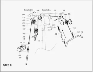
- Attach the Cable for Lat Bar (65) to the opening bracket at the front of the Bridge Tube (8). Note: The ball stopper of the Cable (65) should be underneath the Bridge Tube (8). Attach the Cable (65) onto the Small Pulley (49A) and put the Cap for Small Pulley (50) to the two side of Small Pulley (49A). Note: The Cable (65) has to come out of the Cap (50) from the opening sides. Tighten to the bracket by X1 Hex Head Bolt (26) and X1 Nylon Nut (39).
- Draw the Cable (65) towards the back side of the machine through the upper opening of Upright Support Tube (05) and around Pulley (49), then attach the Pulley (49) onto bracket A as drawing, tighten by X1 Hex Head Bolt (25) and X1 Nylon Nut (39).
- Draw the Cable (65) downwards and around Pulley (49). Attach the Pulley (49) with the Bracket for Pulley (17) on two sides then tighten by X1 Hex Head Bolt (25) and X1 Nylon Nut (39).
- Draw the Cable (65) upwards and around Pulley (49). Attach the Pulley (49) to bracket B and tighten by X1 Hex Head Bolt (25) and X1 Nylon Nut (39).
- Draw the Cable (65) downwards between the two Guiding Tube (07) and fully thread the bolt on the end of the Cable (65) into the top opening on the Select Bar (19).
- Attach the Lat Bar (12) to the front end of the Cable (65), connect by X1 Hook (62).
STEP 7
- Attach one end of the Cable for Butterfly Arm (66) to the hook on the Right Butterfly Arm (10R), tighten by X1 Hex Head Bolt (24), X1 Flat Washer (35A) and X1 Nylon Nut (38).
- Draw the Cable (66) around the Pulley (49) then attach the Pulley (49) to the Pulley Bracket (20) on right side of the Upright Support Tube (05), tighten by X1 Hex Head Bolt (25) and X1 Nylon Nut (39).
- Draw the Cable (66) downward and around the Pulley (49), attach the Pulley (49) to the upper part of Two Way Bracket for Pulley (18) and tighten by X1 Hex Head Bolt (25) and X1 Nylon Nut (39).
- Draw the Cable (66) upward and around Pulley (49). Attach Pulley (49) to the Pulley Bracket (20) on the left side of the upright Support Tube (05), tighten by X1 Hex Head Bolt (25) and X1 Nylon Nut (39).
- Attach the other end of Cable (66) to the hook on the Left Butterfly Arm (10L), tighten by X1 Hex Head Bolt (24), X1 Flat Washer (35A) and X1 Nylon Nut (38).
STEP 8
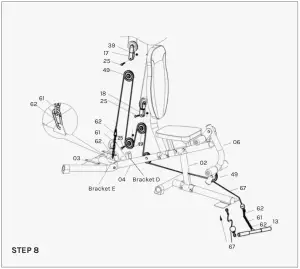
- Attach the end with stopper ball of Cable for Lower Pull Bar (67) to the open bracket Leg Curl Tube (6), around the under side of Pulley (49). Then draw the Cable (67) through the opening space on the lower part of Seat post (02), around the Pulley (49) from under side, then draw the Cable (67) upward and around the upper side of Pulley (49). Attach the Pulley (49) to the under side of Two Way Bracket for Pulley (18), tighten by X1 Hex Head Bolt (25) and X1 Nylon Nut (39).
- Draw the Cable (67) downward and around the under side of Pulley (49). Attach the Pulley (49) to bracket D on the Seat post tube (4) and tighten by X1 Hex Head Bolt (25) and X1 Nylon Nut(39).
- Draw the Cable (67) upward and around the upper side of Pulley (49). Attach the Pulley (49) to the under side of Bracket for Pulley (17) set and tighten by X1 Hex Head Bolt (25) and X1 Nylon Nut (39).
- Draw the Cable (67) downward and connect with bracket E on Rear stabilizer (3) by Chain 6 Links (61) and X2 Hook (62). Note: Adjust the Cable (67) to be tighten enough and lock on certain position of Chain (61) by Hook (62). certain position of Chain (61) by Hook (62).
- Attach the Lower Pull Bar (13) to the front end of Cable (67), connecting by Chain 6 Links (61) and X2 Hook (62).
STEP 9
- Attached the Bracket for Cloth Cover L (73) to the Bridge Tube (08) and tighten by X2 Hex HeadBolt (24), X2 Washer (35 A).
- Do the same procedure for the Bracket for Cloth Cover R (73) to the right side of Bridge Tube (08) by the same parts.
- Attach the Left Cloth Cover (75) to the Bracket for Cloth Cover L (73). 4. Do the same procedure for Right Cloth Cover (75) to the right side by the same parts.
WORKOUT GUIDE
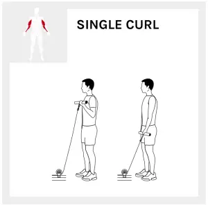
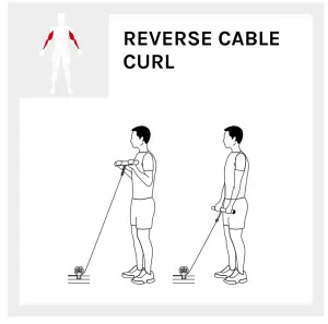
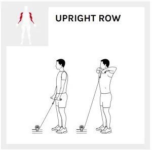
BICEPS & TRICEPS
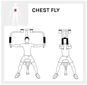
CHEST & SHOULDER
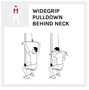
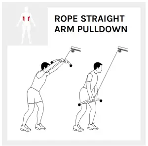
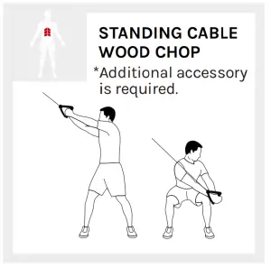
CORE & BACK
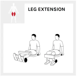
LEGS
EXERCISE GUIDE
 |
PLEASE NOTE:Before beginning any exercise program, consult your physician. This is important especially if you are over the age of 45 or individuals with pre-existing health problems.The pulse sensors are not medical devices. Various factors, including the user’s movement, may affect the accuracy of heart rate readings. The pulse sensors are intended only as an exercise aid in determining heart rate trends in general. |
Exercising is great way to control your weight, improving your fitness and reduce the effect of aging and stress. The key to success is to make exercise a regular and enjoyable part of your everyday life.
The condition of your heart and lungs and how efficient they are in delivering oxygen via your blood to your muscles is an important factor to your fitness. Your muscles use this oxygen to provide enough energy for daily activity. This is called aerobic activity. When you are fit, your heart will not have to work so hard. It will pump a lot fewer times per minute, reducing the wear and tear of your heart.
So as you can see, the fitter you are, the healthier and greater you will feel.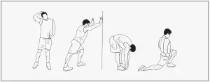
WARM UP
Start each workout with 5 to 10 minutes of stretching and some light exercises. A proper warm-up increases your body temperature, heart rate and circulation in preparation for exercise. Ease into your exercise. After warming up, increase the intensity to your desired exercise program. Be sure to maintain your intensity for maximum performance. Breathe regularly and deeply as you exercise.
COOL DOWN
Finish each workout with a light jog or walk for at least 1 minute. Then complete 5 to 10 minutes of stretching to cool down. This will increase the flexibility of your muscles and will help prevent postexercise problems.
WORKOUT GUIDELINES
|
This is how your pulse should behave during general fitness exercise. Remember to warm up and cool down for a few minutes. |
WARRANTY
AUSTRALIAN CONSUMER LAWMany of our products come with a guarantee or warranty from the manufacturer. In addition, they come with guarantees that cannot be excluded under the Australian Consumer Law.
You are entitled to a replacement or refund for a major failure and compensation for any other reasonably foreseeable loss or damage. You are entitled to have the goods repaired or replaced if the goods fail to be of acceptable quality and the failure does not amount to a major failure. Full details of your consumer rights may be found at www.consumerlaw.gov.au.
Please visit our website to view our full warranty terms and conditions: https://www.lsgfitness.com.au/pages/warranty
WARRANTY AND SUPPORTPlease email us at [email protected] for all warranty or support issues. For all warranty or support related enquiries, please lodge a support ticket first by sending us an email.
 report this ad
References
[xyz-ips snippet=”download-snippet”]