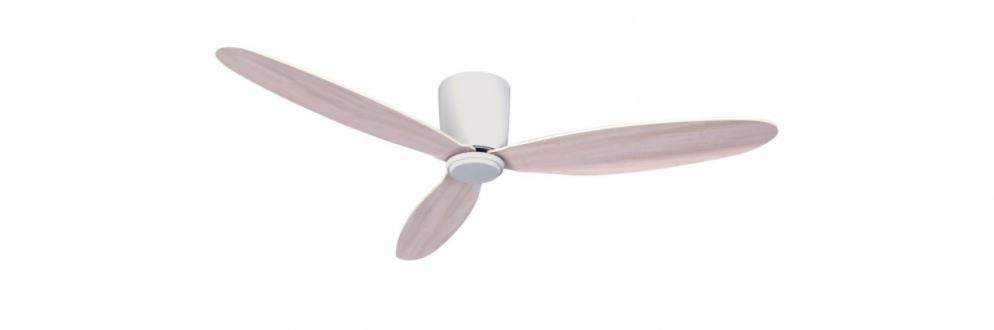
LUCCI 210640 Climate III DC Ceiling Fan
Installation Guide

For customer support, please contact:Tel: +1 (949) 800 8488 Email: [email protected] www.beaconlighting.us.
CONGRATULATIONS ON YOUR PURCHASE
Congratulations on purchasing the latest in energy saving ceiling fans. This fan runs on DC (direct current) power which gives it the benefit of being super energy efficient whilst still maintaining high volume air movement and silent operation.
Energy Saving – The DC motor is the latest technology in fan design. Its highly efficient motor saves up to 65% more energy than ceiling fans with traditional AC motors.Silent operation – This DC fan motor is programmed with a stabilized current which efficiently reduces motor noise.Low operating temperature – The DC power is managed effectively which brings down the motor operating temperature to less than 50℃. This results in a much cooler motor than a standard AC fan and increases the longevity of the motor. 6 speed remote control – Regular AC ceiling fans usually come with only 3 speeds, this DC fan comes complete with a 6 speed remote, which gives greater choice of comfort levels.
SAFETY PRECAUTIONS
Read and Save These Instructions
This product conforms to UL standard 507.
- WARNING -To avoid possible electrical shock, before installing or servicing your fan, disconnect the power by turning off the circuit breaker of the fuse box to the outlet box.
- WARNING – To reduce the risk of fire, electric shock, or personal injury, mount to outlet box marked “acceptable for fan support of 35 lbs (15.9 kg) or more” and use the mounting screws provided with the outlet box and/or support directly from building structure. Most outlet boxes commonly used for the support of luminares may not be acceptable for fan support and may need to be replaced. Consult a qualified electrician if in doubt.
- WARNING – To reduce the risk of fire or electric shock, do not use this fan with any solid-state speed control device.
- WARNING – To reduce the risk of personal injury, do not bend the blade brackets when installing the blade brackets balancing the blades, or cleaning the fan. Do not insert foreign objects in between rotating fan blades.
- CAUTIONS – All wiring must be in accordance with the National Electrical Code (ANSI/NFPA 70) and local electrical codes. Electrical installation should be performed by a qualified licensed electrician.
- To reduce the risk of injury to person, the fan must be mounted with a minimum of 7 feet clearance from the bottom edge of the blades to the floor.
- After marking electrical connections, spliced conductors should be turned upward and pushed carefully up into the outlet box. The wires should be spread apart with the grounded conductor and the equipment grounding conductor on one side of the outlet box.
- This equipment has been tested and found to comply with the limits for a Class B digital device, pursuant to part 15 of the FCC rules. These limits are to provide reasonable protection against harmful interference in a residential installation. This equipment generates, uses and can radiate radio frequency energy and if not installed and used in accordance with the instructions may cause harmful interference to radio communications.
PARTS LIST
- Unpack your ceiling fan and carefully. Remove all parts and hardware.
- Lay out all the components on a smooth surface and make sure there are no components missing before assembling. If parts are missing, return the complete product to the place of purchase for inspection or replacement.
- Check whether the ceiling fan has been damaged during transport. Do not operate/install any product which appears damaged in any way. Return the complete product to the place of purchase for inspection, repair or replacement.
- Examine and identify the parts. Please refer to Fig 1

INSTALLING THE MOUNTING BRACKET
If there isn’t an existing outlet box, then install one using the following instructions:
- Disconnect the power by removing the fuses or turning off the circuit breakers.
- Secure the outlet box (A) (not included) directly to the building structure. Use appropriate fasteners and materials (not included). The outlet box and its bracing must be able to fully support the weight of the moving fan (at least 35 lbs). Do not use a plastic outlet box.
- Figures 2-4 below show three different ways to mount the outlet box (A) (not included).

This fan hanging system supports a maximum 10-degree angled ceiling installation. Fig. 4
NOTE: If you are installing the ceiling fan on a sloped ceiling, you may need a longer downrod to maintain proper clearance between the tip of the blade and the ceiling.NOTE: The ceiling fan must be installed in a location so that the blades are spaced 300mm from the tip of the blade to the nearest objects or walls.NOTE: For angled ceiling installation, the opening of the mounting bracket (B) must be pointed toward the peak.To hang your fan where there is an existing fixture but no ceiling joist, you may need an installation hanger bar (C) as shown in Fig.5. Make sure the hanger bar you purchase has been designed for use with ceiling fans.
INSTALLATION OF THE FAN
INSTALLATION OF THE DOWN ROD (Fig.6)
- Remove the ball joint and dowel pin by loosening the set screw. Remove the lock pin by removing the hitch pin. Do not discard keep these parts, they are required to reassemble later.
- Loosen the set screws on the down rod coupling housing of the fan motor assembly.
- Carefully feed the fan wires up through the down rod. Install the down rod into the down rod coupling housing of the fan motor assembly. Line up the down rod coupling housing holes with the down rod holes and install the lock pin and the hitch pin.
- Secure the down rod by tightening the set screws.
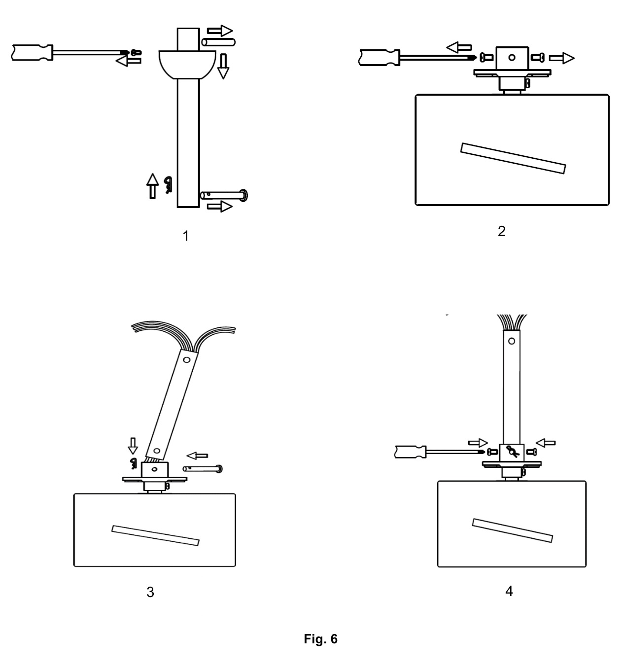
INSTALLATION OF THE HANGER (Fig.7)
- Install the decorative cover onto the down rod and cover the coupling parts. Carefully slide the canopy onto the down rod.
- Reinstall the ball joint and dowel pin back to the down rod and secure by tightening the set screw

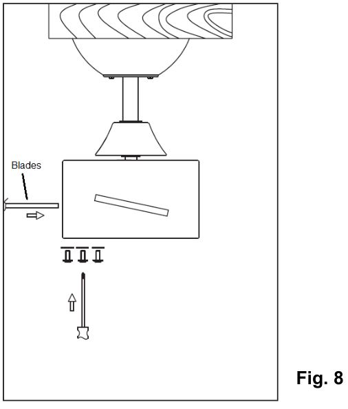
INSTALLATION OF BLADE (Fig.8)
- Insert the blade into the slot of rotating member of fan motor assembly.
- Align and engage the holes of the blade to the blade bracket.
- Secure the blade to the fan motor assembly by tightening the 3 blade screws and washers. Ensure all screws are tightened evenly to reduce the chance of warping or unbalancing. Take care not to over tighten the screws, as this can damage the blades
- Repeat the same process for the other blades.
INSTALLATION OF LIGHT KIT (Optional and sold separately) (Fig.9)
- NOTE: The light kit must be installed by a licensed electrician.
- The light kit is sold separately.
- Connect the wires of the light kit to the motor part via the quick connector.
- Fix the light kit on the motor part then secure it by turning clockwise.
- Install the GX53 lamp to the light kit. Do not exceed the maximum power rating.

HANGING THE FAN
Pass the power supply wires (C) from the ceiling outlet box (B) through the center of the ceiling mounting bracket (D). Install the ceiling mounting bracket (D) on the outlet box (B) with the mounting screws (F) provided with the outlet box and washers (E) provided with fan. Fig. 10
Lift the fan assembly onto the mounting bracket. Ensure the key slot (A) of the hanger ball is positioned on the key pin (B) of the mounting bracket (C) to prevent the fan from rotating when in operation. Fig.11
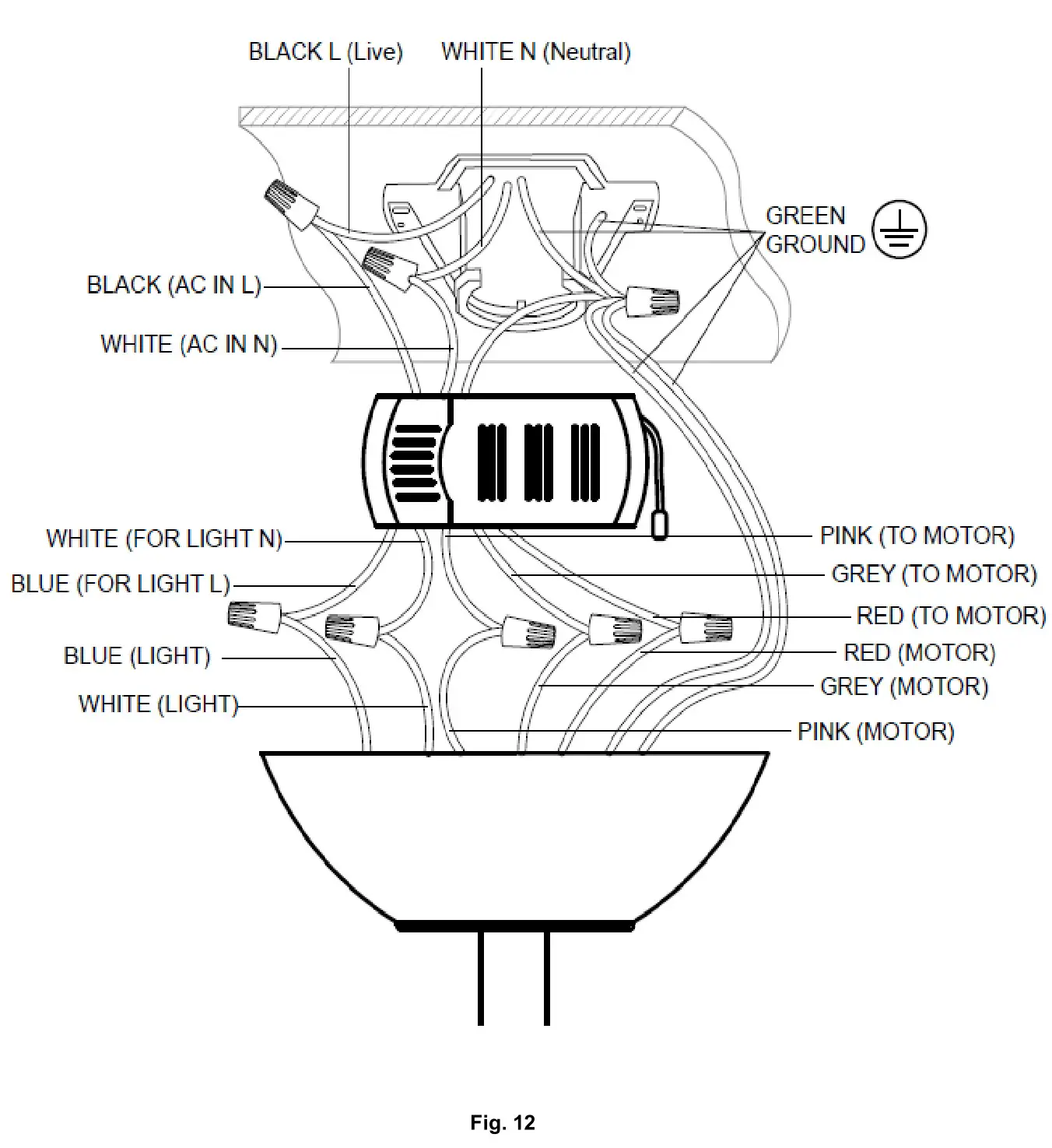
ELECTRICAL WIRING DIAGRAM
WARNING: To avoid possible electrical shock, be sure you have turned off the power at the main circuit panel. Follow the steps below to connect the fan to your household wiring. Use the wire connecting nuts supplied with your fan. Secure the connectors with electrical tape. Make sure there are no loose wire strands or connections.
- Hang the complete fan assembly onto mounting bracket. (Fig. 11)
- Connect the household live supply wire (black) to receiver input wire (black, AC IN L) as shown in Fig. 12.
- Connect the household neutral supply wire (white) to the receiver input wire (white, AC IN N).
- Connect the household ground wire to the fan ground wires (green) from motor, download, fan mounting bracket, and receiver ground wires together. Connect all ground wires together using the twist connector.
- Connect the reveiver output wire (white, for light N) to motor input wire (White, light).
- Connect the reveiver output wire (Blue, for light L) to motor input wire (Blue, light).
- Connect the reveiver output wire (Pink, to motor) to motor input wire (Pink, motor).
- Connect the reveiver output wire (Grey, to motor) to motor input wire (Grey, motor ).
- Connect the reveiver output wire (Red, to motor) to motor input wire (Red, motor ).
- Turn the connecting nuts upward and push the wiring into the outlet box.
- Carefully insert the Remote Receiver above the hanger ball in the remainder spacing in the mounting bracket. Take care not to damage or loosen any of the wiring.
FINISHING THE INSTALLATION
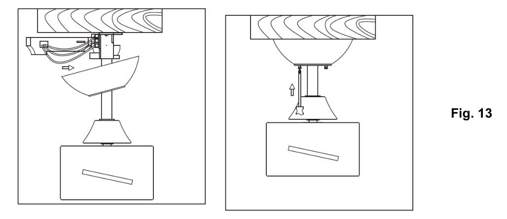
INSTALLATION OF THE CANOPY (Fig.13)
- Loosen the 2 screws at the bottom of the mouthing bracket.
- Slide the canopy up to the mounting bracket and align the key holes on the canopy with the screws on the mounting bracket. Turn the canopy until it locks into place with the narrow section of the key holes and secure it by tightening the two screws. Avoid damaging the electrical wiring prepared previously.
USING YOUR CEILING FAN
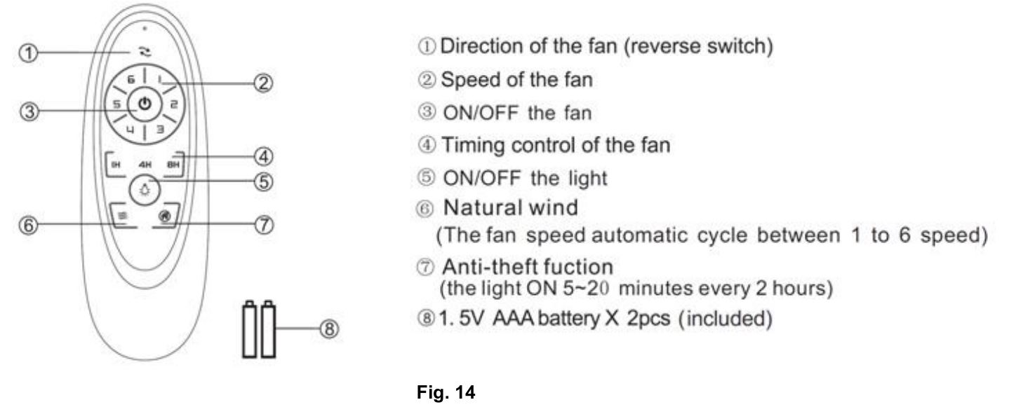
REMOTE CONTROL (Fig.14)
- Open the battery compartment cover by removing the securing screw and insert 2 x AAA battery. Note the correct battery polarity (+/-) when inserting the battery, and then replace the cover and secure with the screw.
- Test the remote by pressing and hold any button. A red LED will be lit up at the top of the remote to indicate that there is power to the remote and it is ready for use to control the fan.
- Follow the guide below to operate the fan and learn the functions
REPAIRING THE FAN RECEIVER & REMOTE PAIRING
NOTE: The pairing of the remote and receiver has been done at the factory.When the ceiling fan is installed, pairing the fan receiver and remote is NOT required.
Should the remote and receiver lose control after installation or during use, the pairing of the remote and the receiver must be repaired. Below are the operating symptoms and method to repair the pairing of the DC ceiling fan remote and receiver.
Issues:
- Loss of control – Fan is only running at high speed after installation
- Loss of control – No reverse function after installation
- Loss of control – Remote cannot communicate with the receiver
Solution:
- Switch off the main power of ceiling fan.
- Switch on the main power of the ceiling fan. Press and hold the On/Off button on the remote for 5 seconds within 30 seconds after switching on. There will be a notification ‘beep’ sound from the receiver to indicate that the paring process is successful.
- Turn on and select the different speed of the ceiling fan to check the operation of the fan.
INSTALLING THE TRANSMITTER HOLDER (Fig.15)
Install the holder (A) to the wall with two screws provided (B), hang up the transmitter by the holder.
AFTER INSTALLATION
WOBBLE:
NOTE: ceiling fans tend to move during operation due to the fact that they are mounted on a rubber grommet. If the fan was mounted rigidly to the ceiling it would cause excessive vibration. Movement of a few centimeters is quite acceptable and DOES NOT suggest any problem.
TO REDUCE THE FAN WOBBLE: Please check that all screws which fix the mounting bracket and down rod are secure.
BALANCING KIT: A balancing kit is provided to balance the ceiling fan on initial installation. Please refer to the instruction on how to use the balancing kit. The balancing kit can be used to assist re-balancing should the ceiling fan become un-balanced again. Store your balancing kit away after installation for future use if required
NOISE:
When it is quiet (especially at night) you may hear occasional small noises. Slight power fluctuations and frequency signals superimposed in the electricity for off-peak hot water control, may cause a change in fan motor noise. This is normal. Please allow a 24-hour “breaking-in” period, most noises associated with a new fan disappear during this time. All electric motors are audible to some extent. Please note that this is not a product fault, and as such is not covered under warranty.
CARE & CLEANING
NOTE: Always turn OFF the power at the mains switch before performing any maintenance or attempting to clean your fan.
- Every 6 months periodic cleaning of your ceiling fan is the only maintenance required. Use a soft brush or lint free cloth to avoid scratching the paint finish. Please turn OFF electricity power when you do so.
- Do not soak or immerse your ceiling fan in water or other liquids. It could damage the motor or the blades and create the possibility of an electrical shock.
- Ensure that the fan does not come in contact with any organic solvents or cleaners.
- To clean the fan blade, wipe with only a damp clean cloth with NO organic solvents or cleaners.
- The motor has a permanently lubricated ball bearing so there is no need to oil.
TECHNICAL INFORMATION
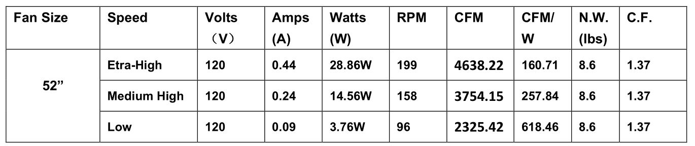
These are approximate measurements. They do not include data for any lamps or fixtures attached to the ceiling fan.
WARRANTY
1 year warranty covers the entire fan. Please refer to warranty card for the details.
 report this ad
![]()
[xyz-ips snippet=”download-snippet”]