
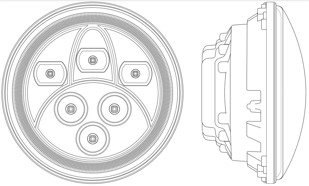
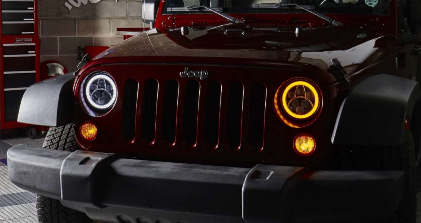
![]() 7” LED sealed beam headlamp with switchback Halos and DRLINSTALLATIONFor 2007 and newer Jeep Wrangler JK
7” LED sealed beam headlamp with switchback Halos and DRLINSTALLATIONFor 2007 and newer Jeep Wrangler JK
![]() SB7HLG201D-BLK. SB7HLG201D-CHR, S81440f11N, SB7150FA-BLK, SB7150FA-CHR, SB7822)0(-BLK, SB7822)0(-CHR, SEI7823XX-BLK. SB7827XX-BLX, S81088WY7-YEL, SB16817-BLK, SB16817-CHR, SB7160XX-BLK. SB7160XX-CHR, SB7060)0C-BLK,SB7060XX-CHR, S87979XX-8LK
SB7HLG201D-BLK. SB7HLG201D-CHR, S81440f11N, SB7150FA-BLK, SB7150FA-CHR, SB7822)0(-BLK, SB7822)0(-CHR, SEI7823XX-BLK. SB7827XX-BLX, S81088WY7-YEL, SB16817-BLK, SB16817-CHR, SB7160XX-BLK. SB7160XX-CHR, SB7060)0C-BLK,SB7060XX-CHR, S87979XX-8LK
These instructions may vary slightly among different model year Wranglers.They can also be used as general guidelines for any year and model vehicle.
![]() CautionThese instructions presume some automotive technical knowledge/repair experience. If you are unfamiliar with basic automotive repair, please seek professional installation assistance.These instructions are not intended to take the place of good workshop practices and common sense. Improper repairs can lead to property damage or personal injury!
CautionThese instructions presume some automotive technical knowledge/repair experience. If you are unfamiliar with basic automotive repair, please seek professional installation assistance.These instructions are not intended to take the place of good workshop practices and common sense. Improper repairs can lead to property damage or personal injury!
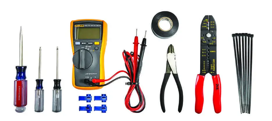
 Tools and supplies needed:
- Assortment of flat, Philips, and Torx screwdrivers;
- 12V test light or multimeter;
- Wire cutters/strippers/crimpers;
- Electrical wire and connectors as needed (see text);
- Electric tape;
- Plastic cable ties.
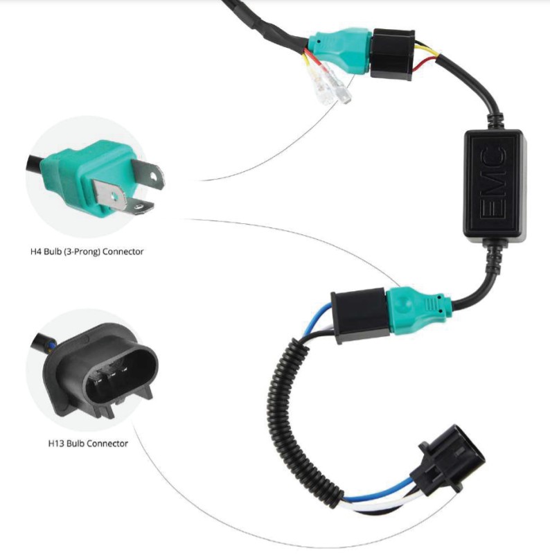
In the box:
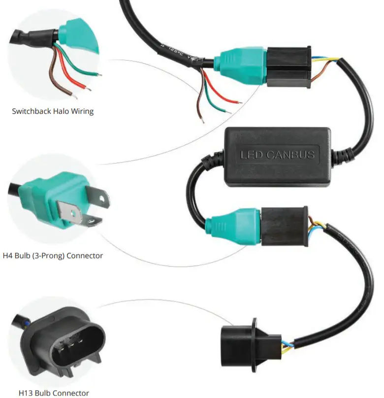
Verify that you have 2 of each of the following, as shown in the photo below:
- 7” sealed beam headlamp, with 3-prong connector plus red and green switchback halo wiring; “LED Canbus” wire connector, with male 3-prong plug on one end and female3-prong plug on other;
- Headlamp “Plug-n-play” wire connector, with female 3-prong plug on one end, and plug to match vehicle headlight connector on another end.
STEP 1: Removal of factory (existing) headlamps
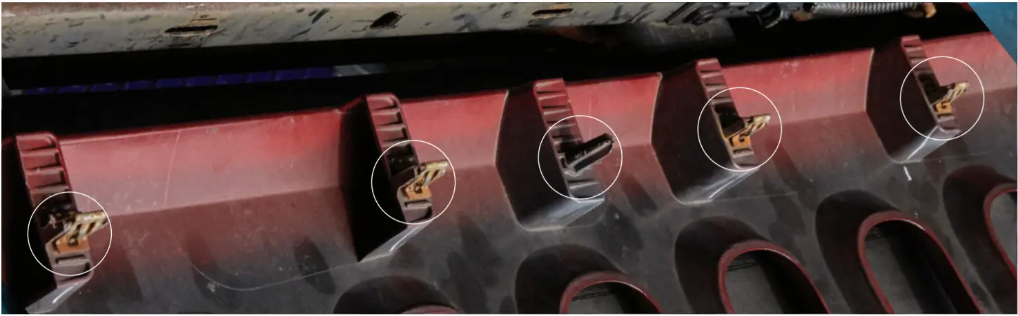
The Jeep headlamp removal requires that the grille be removed first.A, To removes the grille: open the hood; along the top of the grille where it meets the shroud, remove all the plastic clips.
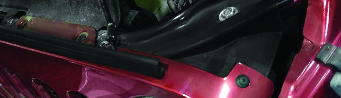
Circled are 3 of the clips to be taken out when removing the Jeep grille |
Use Philips and/or flat blade screwdrivers to remote clips (clip design may differ on your vehicle) |
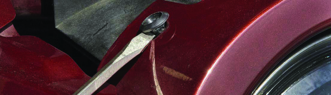
BGently pull the top of the grille outward, away from the car. Reach down and release the parking lamp bulbs and holders, by turning them a quarter-turn. Keep them attached to the wire harness, and place them where they will not be damaged. (They can be left to hang in the opening between the bumper and the body of the Jeep).
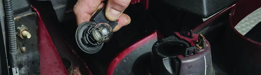 The parking light assembly has already been removed from its location in the grille (circled)
CThe bottom of the grille is held in place by clips. Gently pull on the bottom of the grille until the clips disengage; remove the grille from the car and put it aside in a safe place.
 The bottom clips (circled) are disengaged by pulling at the bottom of the grille
DTo remove the headlamps:a. Remove the metal bezel ring, which is held in place with 4 screws. Use a T-15 Torx bit/screwdriver.
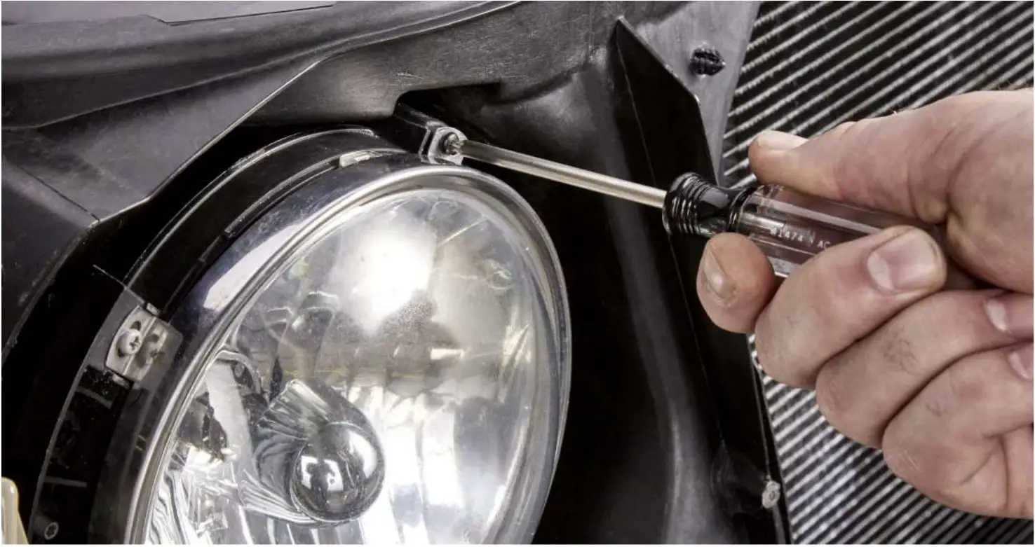 The headlamp bezel is held in place with 4 Torx screws. Note the parking lamp is still attached.
b. As the last screw is removed, hold onto the headlamp, as it could fall.c. Remove the bulb from the assembly with a ¼ turn, remove the headlamp assembly from the car, and put it in a safe place. Unplug the factory harness from the bulb.d. Proceed to Step 2, Method A or Method B.STEP 2: Making the DRL light electrical connectionThe procedure below results in the DRL illuminating WHITE whenever the key is “on” (DRL function). Should you desire different functionality, you would alter the connections as necessary. Below are two recommended methods for making these connections.
- Method A: Making the DRL connection at a 12V accessory socket.
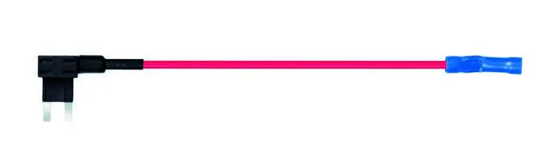
- Method B: Making the DRL connection at the fuse box with an “Add-a-fuse” connector.
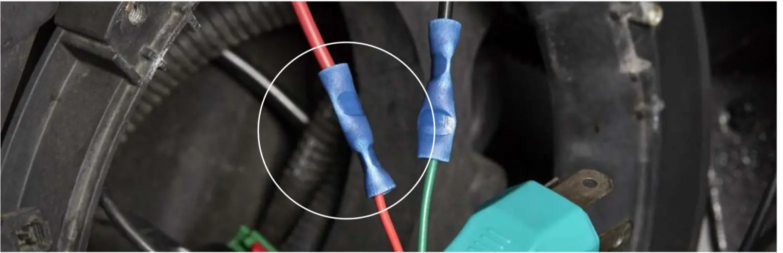
Method A:You may begin this step at either the driver or passenger side of the vehicle; we recommendthe driver side so that the red wire has a shorter path to the driver’s side interior.AThe red halo switchback wire illuminates the DRL, and it must be connected to a circuit that is “hot” with the ignition on.BExtend the red wire to the desired length for proper connection (in the photo below, we extended this wire by crimping on an additional length of red wire).
CPass this red wire through the headlight bezel opening, in order to avoid pinching it when the headlight assembly is installed.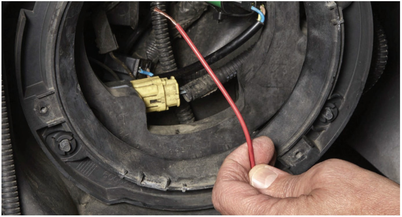
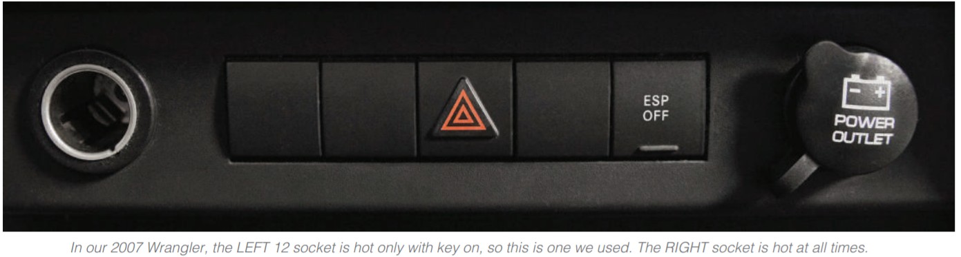
![]() CautionSome Jeeps have TWO 12v accessory sockets, one hot with the key on, and one hot all the time. Select the one which is “on” only with the ignition on. If you select the one which is always hot, the DRL lights will never turn off, and you will drain the battery.
CautionSome Jeeps have TWO 12v accessory sockets, one hot with the key on, and one hot all the time. Select the one which is “on” only with the ignition on. If you select the one which is always hot, the DRL lights will never turn off, and you will drain the battery.
![]() CautionModern (JK) Jeeps use multiplex (Canbus) wiring throughout the vehicle. You CANNOT randomly select a 12V underhood wire and splice it into it without potentially disturbing the Canbus system.
CautionModern (JK) Jeeps use multiplex (Canbus) wiring throughout the vehicle. You CANNOT randomly select a 12V underhood wire and splice it into it without potentially disturbing the Canbus system.DRun the red wire through the firewall and under the dash. Access the wiring behind the 12V accessory socket. (You may need to view videos online to learn the proper way to remove the dash of your vehicle).EWith the ignition on, using the multimeter/test lamp, probe the two wires to find the one which is hot with the key on. Turn off the ignition.FUsing a 3M Scotch-Lok or similar, connect the red wire to that 12V accessory socket wire.GUsing cable ties and/or electric tape, neatly secure the red wire along its travel path.HRepeat the steps above for the other side of the vehicle. NOTE, however, that the 2nd red wire does not need to be routed into the interior; instead, route this red wire across the engine compartment, and connect it to the 1st red wire. Secure all wiring.IProceed to Step 3.Method B:You may begin this step at either the driver or passenger side of the vehicle; we recommend the passenger side so that the red wire has a shorter path to the engine compartment fuse box.AThe red halo switchback wire illuminates the DRL, and it must be connected to a circuit that is “hot” with the ignition on?BExtend the red wire to the desired length for proper connection (in the photo below, we extended this wire by crimping on an additional length of red wire).
CPass this red wire through the headlight bezel opening, in order to avoid pinching it when the headlight assembly is installed.Bussmann®‘‘Add-a-circuit’’. Part# BP/HHH-RPImportant!If there is a fuse in your chosen fuse box location, move it to the lower fuse location in the ‘‘Add-a-circuit’’. If no fuse is there, add one to the lower fuse location.
 Upper fuse locationLower fuse location
![]() CautionPlease research which fuse position to use in order to properly wire your lighting accessory.
CautionPlease research which fuse position to use in order to properly wire your lighting accessory.DChoosing the wrong location could result in major electrical issues.Run the red wire along a path within the engine compartment that will end next to the fuse box.Leave plenty of slack in the wire until all connections are complete.EOnce you have selected the proper fuse position, insert the fuses to your ‘‘Add-a-circuit’’ as follows:a. With the blades of the ‘‘Add-a-circuit’’ pointing down, the lower fuse receptacle is to be used for the existing fuse in your fuse box. Plug that fuse in the ‘‘Add-a-circuit’’.b. The upper fuse receptacle is to be used for the accessory you are adding. Plug that fuse in.For the DRL function of a sealed beam headlight, a 10 AMP fuse is sufficient. But make sure that you use the correct fuse for the location you have selected.c. Plug the ‘‘Add-a-circuit’’ into the selected fuse position.FTEMPORARILY connect the red wire to the ‘‘Add-a-circuit’’ connector (use electrical tape), as you will NOT want to finalize (crimp) the connection until both headlights are installed and all functionality testing has confirmed that all connections are correct.GRepeat the steps above for the other side of the vehicle.NOTE, however, that the 2nd red wire does not need to be routed to the fuse box; instead, route this red wire across the enginecompartment, and connect it to the 1st red wire. Secure all wiring.Note: It is important that the lid fuse box lid can be closed completely. Once functionality has been confirmed, create a channel for the wire to pass through the fuse box wall without being pinched or the fuse box is compromised. The picture below shows the completed wire passing through the fuse box (red box). This channel was created using a triangular file.HProceed to Step 3.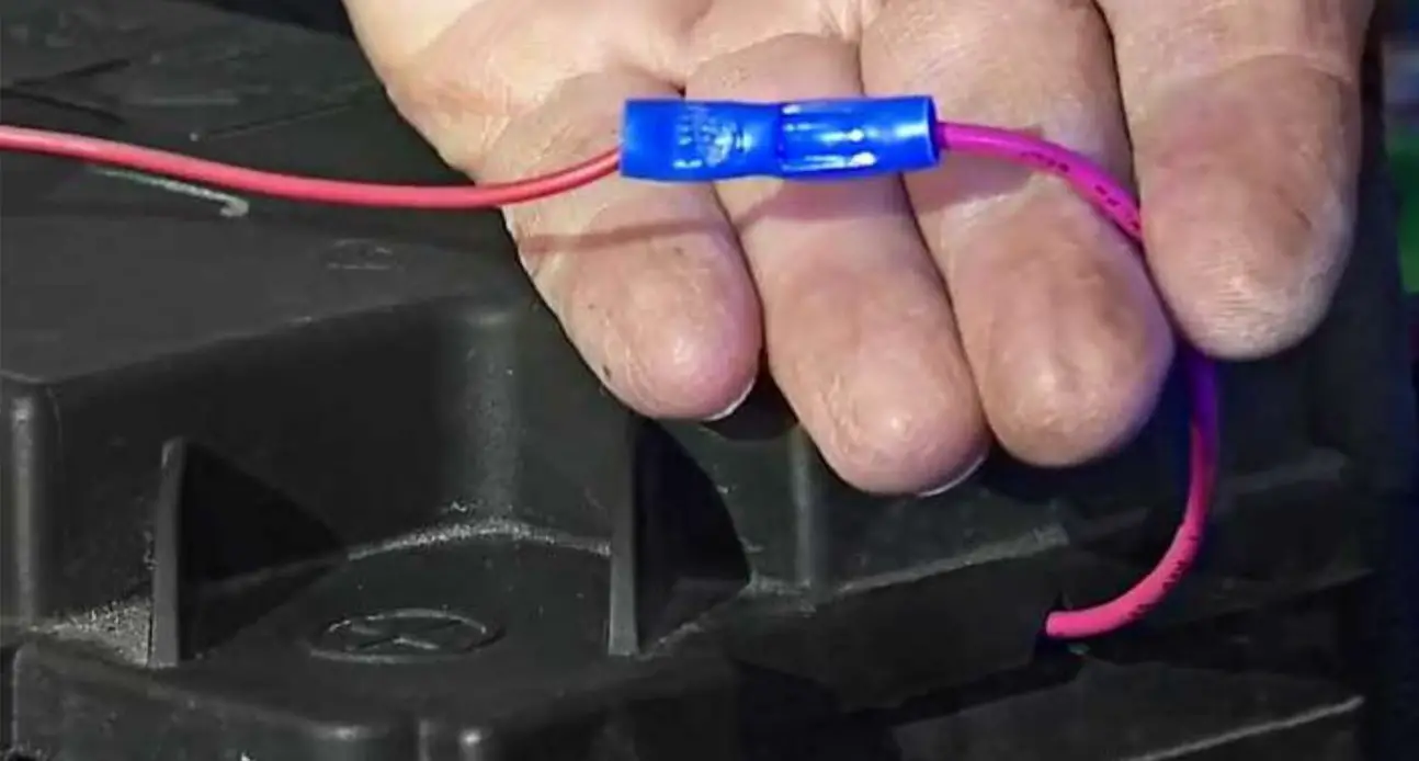 STEP 3: Making the turn signal electrical connections
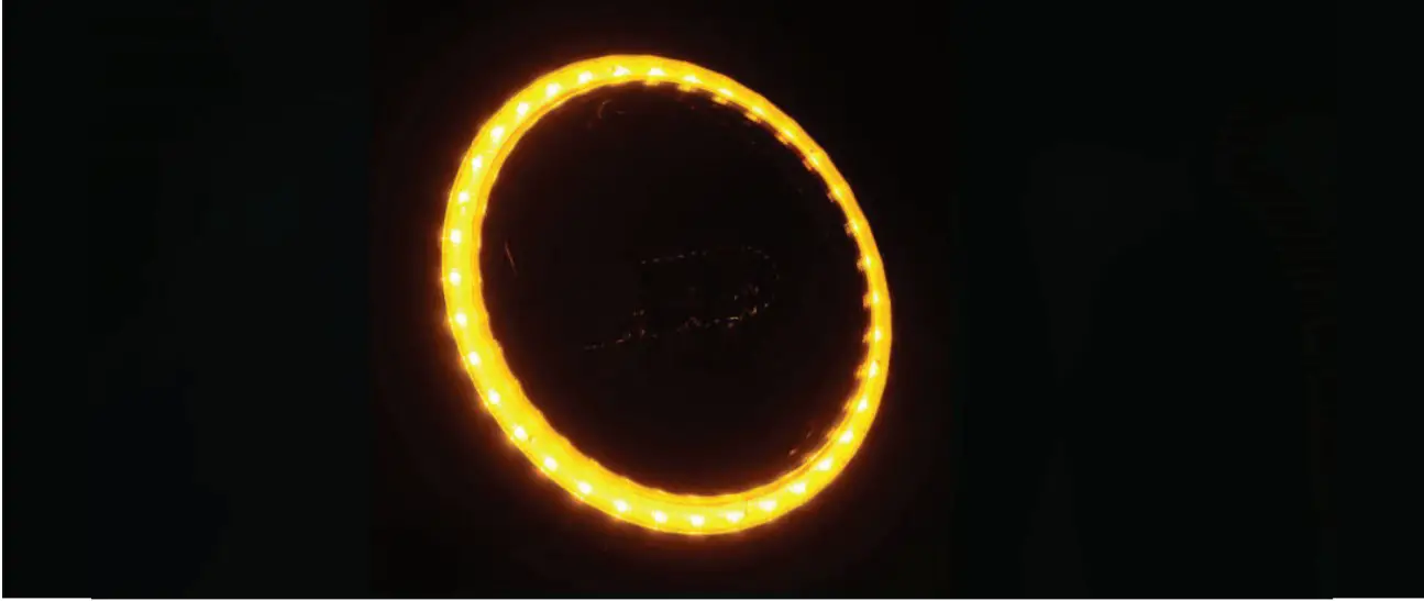
The procedure below results in each halo ring blinking AMBER with its respective turn signal.Should you desire different functionality, you would alter the connections as necessary.AExtend the green halo switchback wire by attaching additional length wire to it as necessary. In the photo below, we crimped an additional length of black wire onto the green wire.
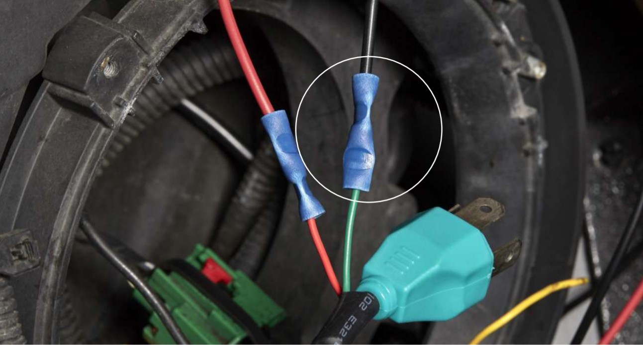
BEnsure that this green/black wire passes through the headlight bezel opening. This is to prevent pinching of the wires during the headlight reinstallation.
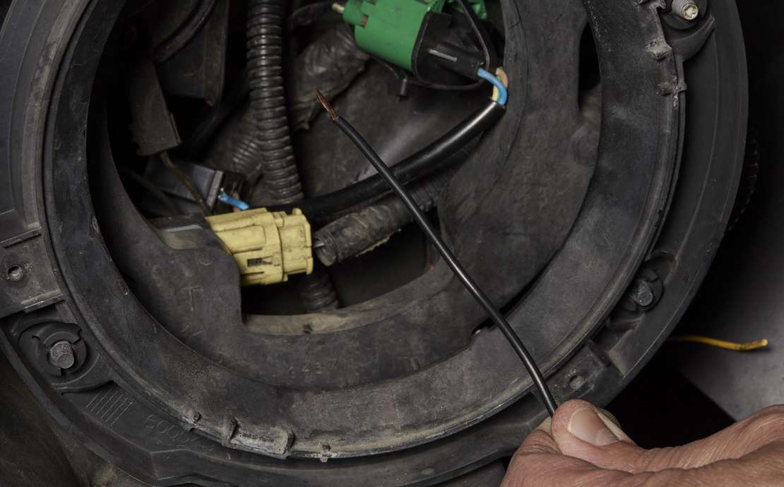
CThis green/black wire needs to be connected to the corresponding signal wire. In order to do this:a. Turn on the ignition;b. Operate the turn signal for the side of the car where you are working.DUsing a multimeter or test lamp:a. Probe the wires at the turn signal bulb socket; the correct wire to tap into will vary from year to year, be sure to test each wire until you find the correct one.b. The correct wire will alternate between 12V and 0V as the signal flashes on and off when using a multimeter. If using a test light, it will flash with the turn signal when you have the correct wire.c. Once you have correctly identified the wire, turn off the ignition.
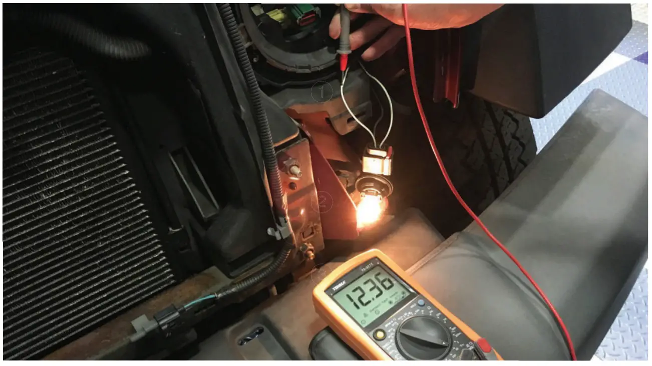
1. Probe from multimeter probes turn signal wire.2. Turn signal bulb is on (actually blinking on/off).3. Multimeter confirms 12V at turn signal wireE Splice this green/black wire into the vehicle’s turn signal wire, using a 3M Scotch-Lok or similar. Securely insulate the splice with electrical tape.
STEP 3: Making the headlamp electrical connections
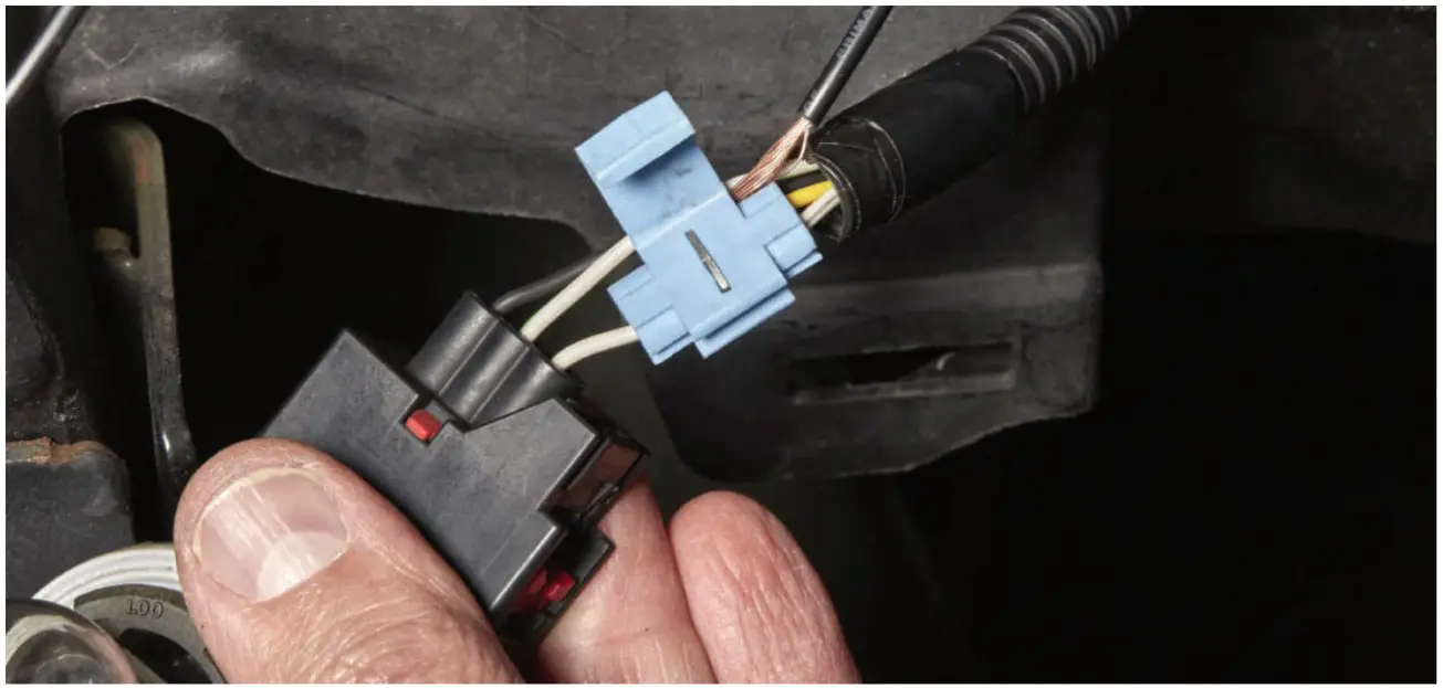
AWorking at one side of the car at a time, begin at the vehicle’s factory headlamp harness. Take the headlamp ‘‘Plug-n-play’’ connector from the LED headlight kit, and plug it into the factory connector.BTake the kit’s ‘‘LED-Canbus’’ wiring connector and plug its male end into the female end of the headlamp plug-n-play connector.NOTE: During Steps C. and D. below, take care to ensure that the headlamp does not drop.CPlug the female end of the ‘‘LED-Canbus’’ wiring connector into the plug on the headlamp assembly.DCarefully route all wiring through the headlamp bezel opening. Take your time and do not force the wiring, there is ample room for all the wires. Use cable ties to neatly secure all wiring. Install the LED headlamp in place by reattaching the bezel ring.ERepeat Steps A-D above for the other side.FTest all lights: low beam, high beam, DRL, turn signals.GIf you used Method B in Step 2, go back and make the final crimp of wiring at the ‘‘Add-a-fuse’’ plug.HReinstall any panels which were removed during wiring installation.IReinstall turn signal bulbs into the grille.JReinstall the grille onto the vehicle.
Check out more light options on our website.
![]()
[xyz-ips snippet=”download-snippet”]