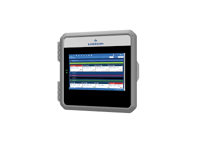
Lumity Supervisory Control Retrofitting Installation

Overview
This technical bulletin describes E3 retrofitting of environments with existing E2 and E2E controllers.
Preparing for Retrofit
When replacing a E2 unit with an E3, there are several major differences that must be taken into account.
- COM 1-4 networks (the RS485 I/O networks) use the same wire and polarity for both the E2 and E2E controllers. No rewiring of the I/O network will be necessary; just unplug the COM 1-4 connectors, and plug them into the I/O port(s) on the E3 PIB (see “Transferring the COM 1-4 Networks” section below).
- E2 and E2E units support an optional Echelon E3 does not currently support Echelon; therefore, any Echelon-based controllers must be replaced with BACnet or Modbus equivalent controllers that utilize BACnet or Modbus interfaces.
Note that the E3 mounting points are the same as E2E, so the fasteners can be reused for the E3 in the same mounting location.
Technical Specifications
| *Operating Temperature | -40°F to 113°F (-40°C to 45°C)*Tested to UL60730-1 standard |
| Operating Humidity Storage Humidity | 5% – 95% RH non-condensing at 90°F 5% – 100% RH |
| 24 VAC | 24 VAC ±20%, 50/60 Hz, Class 2 |
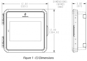
| Dimensions | 12” L x 12.5” W x 3.75 H” |
| 4 RS485 ports | COM 1 = RS485-COM2A and RS485-COM2BCOM 2 = RS485-COM6<ISOLATED>COM 3 = <ISOLATED>RS485COM 4 = RS485-COM4A and RS485-COM4B |
| 2 Ethernet ports | ETH 0, ETH 1 |
| 2 USB ports | J2, J3 |
| External Pollution Rating | All Models: Pollution Degree 3 |
| Rated Impulse Voltage | 2500/4000V |
| Lithium Battery Marking | Caution: The cell used in this device may present a fire or chemical burn hazard if mistreated. Do not disassemble, heat above 212°F (100°C), or incinerate. |
Table 1 – E3 Specifications
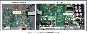
 Transferring the COM 1-4 Networks
 Transferring the COM 1-4 Networks
The COM 1-4 I/O networks on the E2 are where connections to all I/O devices, such as MultiFlex boards are made. The three networks are interchangeable, each one capable of connecting up to approx. 127 devices (contact Technical Services for verification of the maximum number of devices for your network).
The E3 adds an additional COM 3 port (COM 7) on the PIB. This COM port is electrically isolated. The COM 2 port (COM 6) is also electrically isolated. Please refer to the specification table for COM 1-4 RS485 equivalent numbering.
| E3 RS485 | E2 RS485 |
| COM 1A | COM 2A |
| COM 1B | COM 2B |
| COM 2 | COM 6 |
| COM 3 | Not Available |
| COM 4A | COM 4A |
| COM 4B | COM 4B |
Table 2 – E3 RS845 COM Port Naming Translations for E2 Retrofit
E3 Termination Jumper Settings
The network termination jumpers, directly above all COM plugs on the PIB, will need to be set to the same positions as the corresponding termination jumpers on the E2/E2E. The rules for termination on E3 I/O networks are the same as the rules for E2/E2E networks. For each COM port, set the three jumpers to the (terminated) position if the port is at the end of a network segment or the hub of a star configuration, and down NO (unterminated) if the port is in the middle of a segment.
On E3, there is one set of RS485 jumpers for each RS485 port. Jumpers J16-J18 are located directly above the COM2A connector port, and jumpers J20-J22 are located directly above the COM2B port. All the RS485 termination jumpers are used to terminate the devices at the beginning and end of an RS485 Network. If the E3 is at the beginning of an RS485 I/O, MODBUS, or BACnet Network, all three of these jumpers should be set to the up position. For MODBUS and BACnet, the jumpers should all be in the top-most position (MOD). For I/O Net, the jumpers should be in the middle position (I/O). For no termination, set the jumpers to the down position (NO).
Refer to the E3 User’s Manual (P/N 026-1803) for expanded communication setup information.
STEP 1: Powering Down the E2 Controller
Power down the E2 by flipping the ON/OFF power switch to the OFF position on the E2 PIB and remove all field wiring from the E2.
- Disconnect 24VAC power connector and remove from the box.
- Unplug the Ethernet cable and remove from the box.
- Unplug and remove the RS485 connections and remove wires from the box.Labeling Wires: Pro Tip – label all wires and make note to which com ports the wires belong for quick and easy reconnections to the E3
- If a Digital I/O card is present, disconnect the I/O wiring and pull the wiring out of the box. Note that the I/O card is mounted with two screws. Unscrew and remove the card.
- Unscrew the ground terminal wire (2 screws) and remove wire from the box.
Note: Before removing the E2, ensure all wires are removed from the E2 enclosure.
STEP 2: E2 Checklist ✔
- Power switch is in the OFF position on the E2 PIB
- Disconnected the 24VAC power
- Disconnected Ethernet wires
- Disconnected RS485 comm wires
- Disconnected Digital I/O card (if present) removed and wires removed
- Disconnected and unscrewed the Ground terminal wires
- Locate the screws that attach the E2 to the wall or panel and remove the E2
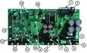
| LEGEND | |
|
1 |
RS232 Port |
|
2 |
Phone Line Jack |
|
3 |
Power ON LED |
|
4 |
Power Terminals (24VACClass 2 only) |
|
5 |
Power Switch |
|
6 |
Earth Ground |
|
7 |
Termination Jumpers
{COM4A and B) – 1/0 Net or MODBUS |
|
8 |
RS 485 COM4A and COM4B Ports |
|
9 |
Plug-In Digital 1/ 0 Card |
|
10 |
Termination Jumpers (COM6)- 1/0 Net or MODBUS |
|
11 |
RS485 COM6 Port |
|
12 |
RS485 COM2A and COM2B Ports |
|
13 |
Termination Jumpers (COM 2A and B) – I/0 Net or MODBUS |
|
14 |
Power Interface Port |
|
15 |
MODEM/COM3 Plug-In |
|
16 |
External Power Connector (for Echelon Repeater Card} |
STEP 3: Mounting the E3
Route all cables, Ethernet, RS485, ground, 24VAC, and I/O back into the box and match to the corresponding com ports.
![]() Pro Tip – refer to the labels on the wires.
Pro Tip – refer to the labels on the wires.
- Once the E2 is out of the wall or panel, mount the E3 into the same location, using the same hardware to attach to the wall or
- Attach the Ground wire to the green ground terminal and fasten by tightening down both screw
- Reconnect the Ethernet cable to the ETH0 port on the E3 processor
- Reconnect the RS485 Com Port
- If a digital I/O card is present, re install the I/O card on the E3 PIB using the same screws and plug the I/O wires into the I/O card
- Reconnect the 24VC power
- Flip the 24VAC power switch on the E2 PIB to
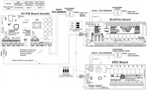 Figure 4 – E3 PIB and MultiFlex Board Wiring
NOTES:
- Transformers for BRO and MultiFlex 16AI must, be center-tapped, 24VAC, 15VA minimum per board.
- Transformer for Multiflex ESR must be center- tapped 24VAC, SOVA PIN 640-0040 minimum per board.
- All other MultiFlex boards can be non center-tapped or center-tapped 24VAC, 15VA minimum per board.
- For MODBUS device wiring, set jumpers above COM connection to MOD (top 2 pins) and connect devices as indicated by the device manual or quick start guide.
 Figure 5 – E3 and XR75 Wiring
STEP 4: Setpoint Conversion Tool
For translating the E2 program, reference the E2 Setpoint Conversion Tool instruction guide: [PDF]
This document may be photocopied for personal use. Visit our website at http://www.climate.emerson.com/ for the latest technical documentation and updates.Join Emerson Technical Support on Facebook. http://on.fb.me/WUQRnt For Technical Support call 833-409-7505 or email ColdChain.[email protected]
The contents of this publication are presented for informational purposes only and they are not to be construed as warranties or guarantees, express or implied, regarding the products or services described herein or their use or applicability. Emerson Climate Technologies Retail Solutions, Inc. and/or its affiliates (collectively “Emerson”), reserves the right to modify the designs or specifications of such products at any time without notice. Emerson does not assume responsibility for the selection, use or maintenance of any product. Responsibility for proper selection, use and maintenance of any product remains solely with the purchaser and end-user.

References
[xyz-ips snippet=”download-snippet”]