
Unit consists of:
AR212TR Automotive Refrigerant Recovery/Recycling/and Recharge Machine6 CFM Vacuum Pump90lb Recovery TankPump Down Valve and BlockAdditional Ball Valves for Tank Liquid and Vapor hoses8’ Low and High Side Service hosesLow and High Side ¼ Flare Service ValvesOperation Manual2 cotter pins
End User to provide:RefrigerantOEM specified A/C system oil
Specifications
AR212TR Specifications
Refrigerant R-12*, R-22, R-134a**, R-502, R-401A, R-402A, R-404A, R-407C,and R-409ADimensions 51cm (20”) wide x 71cm (28”) deep x 127cm (50”) highWeight 85 kgs (110 lbs)Operating Range 4C (40F) to 49C (120 F)Power Supply 220-240VAC, 1PH, 50HzCylinder Capacity 27 Liter TankVacuum Pump 6 CFMPower Consumption 485 WMoisture Size/Capacity 650 ccm / 60-ml of waterScale Resolution 10 g / 0.25 ounces*This unit is certified for R-12 mobile A/C systems per SAE J1990 and J1991.**This unit is certified for R-134a mobile A/C systems per SAE J2099 and J2210.
Introduction
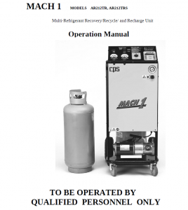
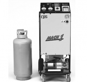
Thank you for purchasing the CPS Mach 1 AR212TR series unit. CPS is dedicated to give you the fastest and most reliable equipment to meet all your mobile A/C service requirements. In doing this CPS has integrated its latest technology and incorporated state of the art features while improving reliability and speed.The AR212TR series is a Multi-refrigerant that automaticallyrecoverys/recycles/evacuates and recharges. The AR212TR is designed for small as well as larger mobile A/C systems. The AR212TR is equipped with a built in pump down valve to clear out the refrigerant from the last job. Simply hook up the service hoses, choose the operation and allow the unit to perform its job until it automatically shuts off. Then follow the pump down directions to prepare the unit for the next refrigerant.The AR212TR series utilizes a single pass coalescing and distillation recycling system, which means that when the AR212TR recovers it also recycles. Thus the recovery tank always contains the cleanest refrigerant possible for future use.The Mach 1 AR212TR series utilizes a 450 W compressor, non-restrictive control valves and large ported solenoid valves to make it one of the fastest refrigerant handling systems in its class.The AR212TR utilizes a unique compressor assist charging method that does notrequire a heater blanket. This gives the unit one of the fastest recharge rates of up to 1.5 kg per minute. The unit will even notify you if there is not enough refrigerant in the recovery tank to perform the charging operation!
The following are additional features:
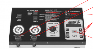
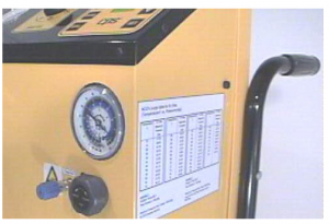
- Integrated Manifold Gauge Set. Visually see how the mobile A/C system is operating.
- A highly accurate electronic charge scale has been integrated into the AR212TR control system
- Hour meter give the user immediate information on the status of the moisture filtration system.
- Tank overfill protection is provided by the electronic scale software and hardware.
- Automatic high-pressure shut-off with indication light.
- Modular component design and a hinge front panel allow for easy service access.
- Built in Oil and/or Dye vacuum injection with a 480-ml (16-oz) reservoir.
- The unit has the ability to recharge large amounts of refrigerants.
- One bolt-external filter access system allows the user to change the filter core in less than 5 minutes.
- Replace only the filter core. This will greatly reduce the maintenance cost of filter changes.
- The control valves utilize CPS’s fully ported Teflon valves.
- Heavy-duty construction, powder coated steel cabinet mounted onto a 2.5 cm tubular steel wrap around frame.
- 25 cm pneumatic rear wheels and 10 cm swivel casters give this unit excellent maneuverability under the worst of conditions.
- Recovers and Evacuates through both the high and low side service hoses.
- Automatic Oil Drain System.
- Acculevel Compressor oil level system, maintains the proper oil level in the AR compressor.
To help you get a good start, please continue to carefully read the balance of thismanual. This manual contains important information on the proper procedures for operating this equipment. Please pay close attention to the safety information,Warnings, and Cautions provided throughout this manual. Always remember“Safety First”.
General Safety Instructions
Only qualified service personnel should operate this unit. Most states, countries,etc… may require the user to be licensed. Please check with your localgovernment agency.
Danger- this unit’s recovery tank contains liquid refrigerant. Overfilling of the recovery tank may cause a violent explosion resulting in severe injury or even death.
Danger- Only use the recovery tank provided with this unit. See distributor for replacement tanks.
Danger- Avoid breathing refrigerant vapors and lubricant vapor or mist. Breathing high concentration levels may cause heart arrhythmia, loss of consciousness, or even cause suffocation.
Caution- all hoses may contain liquid refrigerant under pressure. Contact with refrigerant may cause frostbite or other related injuries. Wear proper personal protective equipment such as safety goggles and gloves. When disconnecting any hose, please use extreme caution.
Caution- avoid breathing refrigerant vapors and/or lubricant mist. Exposure may irritate eyes, nose, throat, and skin. Please read the manufacturers Material Safety Data Sheet for further safety information on refrigerants and lubricants.
Caution- to reduce the risk of fire, avoid the use of extension cords thinner than NO. 14 awg. (1,5mm²) to prevent the overheating of this cord please keep length to a minimum.
Caution- do not use this equipment in the vicinity of spilled or open containers of gasoline or other flammable substances. Make certain that all safety devices are functioning properly before operating the equipment.
This AR212TR sereis is intended for use with R-12, R-134a, R-22, R-404a, R-402a, R-401a, R407C, R409a, R-500 and R-502 refrigerants. Other refrigerants can be used. Proper pump down of the system is required when changing to different refrigerant. Mixing of different refrigerants will cause this equipment and the mobile A/C system to prematurely fail. Note: It is very expensive to destroy mixed or damaged refrigerants.
Make sure that recovery tank is placed on the load cell platform at all times. Failure to do so will disable certain safety features of this unit.Always disconnect power source when servicing this equipment.
Initial Equipment Preparation
- Carefully unpackage the AR212TR series unit.
- Find the box marked “Open Me First”. Open and remove contents.The contents are as follows:– Red 8 ft service hose w/high side service valve– Blue 8 ft service hose w/low side service valve– Operation Manual– 27liter.Recovery Tank (separate box) Note: Each type of refrigerant recovered will need its own recovery tank.– Two 3/16 Cotter Pins
- Pull the 10” Wheel as far as it will move. It should move about 3 cm. Place the provided 3/16 Cotter pin into thehole though the axle just behind the wheel hub. Repeat this procedure for the other side. This will extend thewheelbase to 56 cm.
- Attach the Blue 8 ft service hose w/Low Side Service valve onto the low side manifold fitting just below the Low SidePressure Gauge and Valve. Place the Low Side Service valve onto the adapter on the back of the unit for storage.
- Attach the Red 8 ft service hose w/High Side Service valve onto the high side manifold fitting just below the HighSide Pressure Gauge and Valve. Place the High Side Service valve onto the adapter on the back of the unit forstorage.
- Inspect the unit for loose hoses. Also make sure that the tank is centered on the scale platform so that it does nottouch any of the protective framework. Note: The load cell will not weigh accurately if it is touching theframework.
- Check the oil level in the Vacuum Pump. Make sure the vacuum pump power switch is in the “ON” position, thevacuum pump hose is properly connected and the vacuum pump valve is open. Also check that the vacuum pumppower cord is properly plugged into the receptacle on the bottom of the unit. Read vacuum pump manual forfurther maintenance issues.
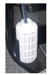
- If desired, please add OEM recommended A/C oil and /or dye to the Oil Injection Bottle. Do not use Oil InjectionValve unless bottle is filled above the 60ml mark.
- The next step will be to evacuate the AR212TR and the AR212TR recovery tank.a) Attach the provided power cord to the electrical inlet. Turn power switch to “I” (On) position.b) Make sure the yellow tank hoses are properly connected to the recovery tank. One hose is marked LIQUID, the other ismarked VAPOR. Open the tank valvesc) Connect Low Side Service Valve to the Purge port.d) Open Purge Valve, the Low Side Service Valve, and the Low Side Manifold Valve.e) Select “EVACUATE” on the Mode Selector Switch.f) Turn the Vacuum Timer to 30 minutes. Push the “Start 1” button. The vacuum pump should begin to operate. It should bevisually noted that the low side and purge gauges should fall into a deep vacuum. When the low side gauge reads –25 inhg vac. vacuum, turn the power switch to “O” (Off) position. After 5 minutes, observe the low side gauge for any vacuumloss. If the gauge rises, this could indicate a leak. If a leak exists, find and repair it, then repeat this procedure.g) If the low side gauge does not lose vacuum, the system is ready for the initial refrigerant transfer.h) Close the Purge Valve. Close and remove the Low Side Service Valve.10. The next step is the procedure to add new refrigerant to the AR212TR recovery tank.a) Connect the Low Side Service Valve to the liquid fitting on a virgin refrigerant supply tank.b) Open Low Side Manifold valve. Also make sure that both tank valves are open.c) Turn the power switch to “I” (On) position.d) Push the “REFILL” key on the keypad.e) Select “RECOVERY” on the Mode Selector Switch.f) Push the “START-1” switch. NOTE: To speed up the refill process, make sure that liquid refrigerant is being recovered.g) The LCD will display the total amount of refrigerant in the recovery tank. The refill procedure will automatically shut-off2 different ways. (1) If the refrigerant weight in the recovery tank reaches 25 kg. or (2) the vacuum switch activates due tothe virgin supply tank being empty.11. Select desired language for LCD display by pushing the “+” key when turning on the power switch. The LCD willshow the current language selection. Use the “-” key to scroll to the desired language. Push “START-2” key whenthe desired language is displayed.
Congratulations, The Mach 1 model AR212TR series is now readyfor service use. Please refer to the rest of this manual for properoperating instructions.
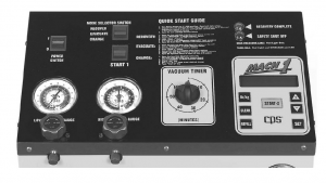
Quick Start Guide
IMPORTANT: Before using this Quick Start Guide it is highly recommended that the user completely read and understand this entire manual. Failure to operate as specified could result in damage to the unit, which could also lead to loss of warranty.
- Turn the Power switch to “I” (On) position. Open all Tank and Tank Hose valves.
- Connect the Service Valves on the end of the 8 ft red and blue service hoses to the low and high side serviceports of the mobile air conditioning system.
- Open the Low and High Side Service Valves.
RECOVERY:
- The Low and High Side Manifold valves should be open.
- Select “RECOVER” on the Mode Selector Switch.
- Push “CLEAR” key until the scale reads zero.
- Push “START 1” switch.
- Unit will run until “RECOVERY COMPLETE” light energizes.
- After 2 minutes, measure and record drained oil.
EVACUATE:
- The Low and High Side Manifold valves should be open.
- Select “EVACUATE” on the Mode Selector Switch.
- Turn Vacuum Timer to desired setting.
- Push the “START 1” switch.
- When the Vacuum Timer expires, close the Low and High Side Manifold valves.
- Check Low and High Pressure gauges to confirm vacuum.
- Open Oil Injection Valve to add oil and/or dye to the A/C system.
CHARGE:
- The Low Side Manifold valve should be open. The High Side Manifold valve must remain closed.
- Select “CHARGE” on the Mode Selector Switch.
- Press “SET” key.
- Use +/- keys to set desired charge.
- Push “START-2” key.
Important: Do not move the unit when operating in the Recovery orCharge Mode. Moving the unit during operation will cause weightreading inaccuracies.
Recovery Operation
This unit features a single pass coalescing-distillation recycling process. As the refrigerant is being recovered, it is also being recycled to meet or exceed SAE J1990 (R-12) standards. Please read the following instructions on the recoveryprocess. Plug the power cord into the appropriate power supply. Turn the Power switch to “I” (On) position. The unit’s LCD will begin a self-test. Once complete the LCD will display the current refrigerant weight in the recovery tank.
 Connect the Low and High Service fitting on the end of the 8 ft blue and redservice hoses to the low and high side service ports of the mobile air conditioning system.
Open the Low and High Side Service ball valves. You can now run the mobile A/C system to read system operating pressures. Once diagnosis is complete, turn off mobile A/C system.
There must be a minimum pressure of 7 psig in the mobile A/C system (ifbelow 7 psig, there maybe excessive air and very little refrigerant to recover)to continue with the recovery process.
 Open the Low and High Side Manifold valves.
Select “RECOVER” on the Mode Selector Switch
Push “CLEAR” key until the scale reads zero. The LCDwill read “RECOVERED REFRIG”, “0kg 000g”.The LCD will display the amount of refrigerantrecovered throughout the recovery process.Push “START 1” switch to begin the recovery process
The unit will run until the “RECOVERY COMPLETE”light (green) energizes. After waiting 5 minutes checkthe Low and High Side Pressure gauges to verify a slightvacuum pressure.
Note: If the pressure rises above 5 psig, the unit willautomatically restart. This will repeat until thepressure remains below 5 psig.
 Once the recovery process has been completed, the oil removed from the mobile A/C system wilautomatically drain into the 16 oz bottle. Please record the amount removed. The procedure to re-inject oil will be discussed in the EVACUATION section. Once measured, please dispose of the oil in accordance with local or federal regulations. If required, also record the amount of refrigerant recovered. The recovery process is complete. Proceed to repair the mobile A/C system.
Evacuation Operation
After the mobile A/C system has been repaired, it will be necessary to evacuate all the non-condensables (NCG’s) and moisture before recharging. After time, moisture and non-condensables can lead to severe damage of an A/C system.Moisture can create an acid, which will lead to premature material failure, and non-condensables will elevate system pressures, which could reduce the life expectancy of the system compressor.
It is necessary to have the “RECOVERY COMPLETE” light (green) on before Evacuation Operation. If the “RECOVERY COMPLETE” light is not on, run the Recovery Operation.
 Connect the Low and High Service fittings on the end of the 8 ft blue and red service hoses to the low and high side service ports of the mobile air conditioning system.
Open the Low and High Side Service ball valves
Select “EVACUATE” on the Mode SelectorSwitch
MACH 1 AR212TR, AR212TRS Multi-Refrigerant Recovery/ Recycle and Recharge Unit Operation Manual
The vacuum pump will run until the VacuumTimer has expired. Close both the Low and High Side Manifold valves.
Check the Low and High Side gauges to verify vacuum pressure. Check with the OEM for vacuum level recommendations. Repeat this process if necessary.
Once the proper vacuum level has been reached, proceed to re-inject the A/C OEM recommended oil and/or dye into the mobile A/C system.Please make sure that there is enough oil in the Oil Injection bottle beforeproceeding. Caution: Air could be injected if the oil level in the bottle drops below the 60 ml line. Open the Oil Injection valve slowly. Once the required amount of oil has been injected, close the Oil Injection valve. The unit is now prepared for Charging

Charge Operation
The AR212TR incorporates a highly accurate electronic charging scale. The electronic scale is always active whenever the power switch is on. The AR212TR incorporates a push-pull charging method, which speeds up the charging processand improves the accuracy. No heater blanket is ever required.
Caution: The Evacuation process should always precede the Charging process. If the A/C system is not properly evacuated, moisture and non-condensables can lead to severe damage of an A/C system. Moisture can create an acid,which will lead to premature material failure, and non-condensables will elevate system pressures, which could reduce the life expectancy of the system compressor.
Connect the Low and High Service fittings on the end of the 8 ftblue and red service hoses to the low and high side service ports ofthe mobile air conditioning system.Open the Low and High Side Service ball valves.

 Open the Low Side Manifold valve only. The High Side Manifold valve must remain closed. Select “CHARGE” on the Mode Selector Switch. Push “SET” key. Then use the “+” or “-“ keys to set the required charge. Also use the “lb/kg” key to select unit of measure. Push “START-2” key to begin the charging process.
The charging software will check to see if there is enough refrigerant in the tank to complete the charge. In order to start the charge process, the refrigerant in the recovery tank must be greater than the charge amount programmed plus 2kg. If there is not enough refrigerant to perform the charge process, the LCD will prompt the user that “REFRIGERANT LOW” and the Red Indicator will energize. The user will need to follow the instructions to refill the refrigerant tank before proceeding with charge.
Otherwise the unit will run until the programmed charge weight has been met. The LCD will give the user continuous updates on the charge status. The unit should charge approximately 1 kg. per minute.
Once the charge is complete, close the Low Side Manifold Valve (the High Side Manifold Valve is already be closed). You can now start the mobile A/C system to check the system operating pressures.
Close and remove Low and High Service valves once satisfactory operation is achieved.
Important: Do not move the unit when operating in the Recovery orCharge Mode. Moving the unit during these processes with causeweight reading inaccuracies.
Pump Down Procedure
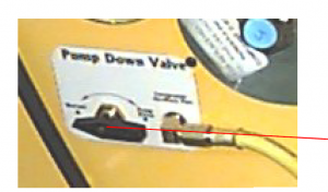
The AR212TR series are equipped with a Refrigerant Pump Down Valve system. This is to be used when changing from one refrigerant (such as R-12) to another refrigerant (such as R-22). It is extremely important to follow thesedirections. Failure to do so could result in cross-contaminated refrigerant.
Please follow the directions below for the proper pump down procedure.
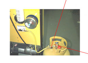
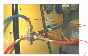 Step1: Close the Tank Liquid and Vapor valves. Close the Liquid and Vapor Tank Hose valves. Disconnect both Tank hoses fromTank. Step 2: Connect the Low and High Service valves on the end of the 8 ft blue and red service hoses to the Pump Down Block located onthe back of the unit. Step 3: Connect the Liquid and Vapor Tank hoses to the Pump Down Block located on the back of the unit.
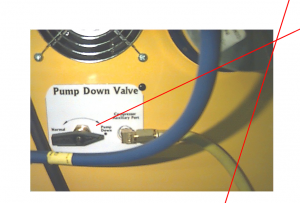 Step 4: Connect the Auxiliary Hose to the Vapor Port the tank. Open the Tank Vapor valve and the Auxiliary Hose valve. Step 5: Turn the Pump Down Valve to the Pump Down position. Step 6: Open the Low and High Side Manifold valves, Low and High Side service valves, and the Liquid and Vapor Tank Hose valves.Step 7: Select “RECOVER” on the Mode Selector SwitchStep 8: Push “START 1” switch to begin the recovery process.The unit will run until the “RECOVERY COMPLETE” light(green) energizes.
Step 9: Select “EVACUATE” on the Mode Selector SwitchStep 10: Turn the Vacuum Timer knob to 15 minutes.Step 11: Push “START 1” switch to begin the evacuation process.The vacuum pump will run until the Vacuum Timer has expired.Check vacuum level on Gauges. A minimum of 25”in hg
 Step 12: Close the Low and High Side Manifold valves, recovery tank vapor valve, auxiliary hose valve, Liquid and Vapor Hose valves, and Low and High Side service valves.Step 13: Disconnect Auxiliary hose from tank. Remove tank from unit.
Step 14: Install the next selected refrigerant tank onto the unit.Make sure that it is centered on the scale.
 Step 15: Connect the Liquid and Vapor Tank Hoses to the respective Tank ports. Make sure liquid hose goes to liquid tank port and vapor hose goes to the vapor tank port. Step 16: Open all Tank valves and Tank hose valves. Step 17: Turn the Pump Down valve back to the normal position. Step 18: Check for leaks.
Non-
Condensable Gases
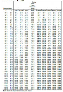
From time to time it will be necessary to purge the recovery tank of non-condensable gases(NCG’s). The NCG’s are picked up from leaks in a/c systems, service valves left open,etc…The best time to check for purging is first thing in the morning before using the unit. This gives the refrigerant time to stabilize.Use the NCG’s purge table below to determine if the refrigerant in the recovery tank needs to be purged of NCG’s. If purging is required:1. Open the purge valve. The NCG’s will vent though the purge port.2. Once the pressure of the tank falls below the NCG Gases purge table, close the purge valve.
Maximum Refrigerant Vapor Pressure Chart (Temp F/C vs.Pressure psig)
Routine Maintenance
Filter Maintenance- the Mach 1 AR212TR is equipped with a 650 ccm solid core desiccant cartridge. This filterdrier cartridge should be changed if:
1) The Moisture Indicator turns from purple to a red color. See the color ring around the Moisture Indicator for adirect comparison of moisture levels in the refrigerant. Replace when “wet” refrigerant is indicated.-or-2) The unit has been used for 50 hours as indicated by the hour meter.
Replace the filter cartridge as follows:
Danger: Always assume that high-pressure refrigerant exists in the Filter Shell. Failure to do so may result in bodily injury.
- Run the unit per the Recovery procedure. Note: Leave the Low and High Service valves closed.
- The unit will automatically shut-off when the vacuum switch has been activated. This will remove any residualrefrigerant on the low side of the unit.
- Open the Oil Drain valve before removing the Filter Access Cap. If there is any remaining refrigerant pressure, itwill be vented through the Oil Drain valve.
- Loosen the Filter Access Cap as shown in Figure 1. Rotate the Cap counter-clockwise and pull outward. The capwill release once the quick release mechanism aligns with the flange on the Filter Shell.
- Remove the spring-loaded insert to expose the Filter Drier Core as shown in figure 2.
- Remove and dispose of the old Filter Drier Core as shown in figure 3.
- Replace filter cartridge with CPS part # ARXF
- Reassemble the remaining components. Make sure the rubber gasket is properly placed in the Filter Shell flange.
- Remember to close the Oil Drain valve once reassembly is complete. !After replace the filter cartridge, it is
necessary to conduct a leak test for the complete unit !! Unit is now ready for operation.

Vacuum Pump Oil- the Mach 1 AR212TR is equipped with a vacuum pump. It may be necessary to occasionally add additional vacuum pump oil. View the oil level through the sight glass provided on the vacuum pump.
If it is noticed that the vacuum pump is not performing as it did when new, completely drain and refill with new vacuum pump oil. Contaminants in the vacuum pump oil will greater effect the performance.
Use the Vacuum Pump manufacturers recommended vacuum pump oil.Please read the vacuum pump operation manual for further maintenance details.
End of the Day Maintenance- as a matter of precaution, close both recovery tank valves. Close all other valves. Please note that CPS does not take responsibility for lost refrigerant.
Trouble Shooting Chart
Problem: The unit will only pull down to 0 pressure or a slight vacuum.Solution: Make sure that both the Oil Drain Valve and Oil Injection Valve are fully closed. If left open in the during the recovery operation, air will be pulled through the valve. Solution: Make sure that both the Low and High Side Service Hoses are leak tight.
Problem: The unit fails to charge the automobile. Message on LCD will read “CHECK CONNECTIONS”.Solution: Make sure that both tank valves are open. Also check that the liquid hose is connected to the liquid port ofthe tank. Solution: Make sure the High and Low Service valves are open.
Problem: The unit completed its charge operation, but it seems that the automobile is low on charge.Solution: It is crucial that the High Side Manifold valve be closed when charging. If left open some of the charge will reenter the unit; thus a shortage will result in the automobile A/C system. Repeat recovery, evacuation, and chargeoperations.
Problem: In charge operation, after pushing the START-2 key the LCD reads “LOW REFRIGERANT” andwill not charge. Solution: The unit’s refrigerant tank needs to contain a minimum of 2 kgs plus the charge amount before charging. Use the refill procedure to add additional refrigerant to the tank.
Problem: During the recovery operation the unit is shut-off by the high-pressure switch. This should be noted by the red light energizing with no LCD message.Solution: Make sure that both tank valves are open. Push the HPCO reset button to reset unit.
Problem: During the recovery operation the unit is shut-off by tank overfill safety system. The red lightenergizing and a LCD message “TANK FULL” will note this condition.Solution: It will be necessary to charge approximately 5 lbs. into an empty refrigerant cylinder. Connect the High Side Service valve to the tank liquid port and the Low Side Service valve to the tank vapor port. Follow the directions forthe charge operation.
Replacement parts can be obtained from your local CPS distributor. Forinformation of the closest CPS distributor call, fax or email to:

Read More About This Manual & Download PDF:
MACH 1 AR212TR, AR212TRS Multi-Refrigerant Recovery/ Recycle and Recharge Unit Operation Manual – MACH 1 AR212TR, AR212TRS Multi-Refrigerant Recovery/ Recycle and Recharge Unit Operation Manual –
[xyz-ips snippet=”download-snippet”]