![]()
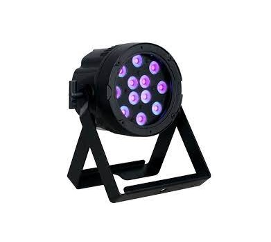
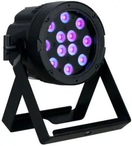
Prisma PAR 20
User Manual
©2021 MAGMATIC EFFECTS all rights reserved. Information, specifications, diagrams, images, and instructions herein are subject to change without notice. MAGMATIC EFFECTS logo and identifying product names and numbers herein are trademarks of MAGMATIC EFFECTS. Copyright protection claimed includes all forms and matters of copyrightable materials and information now allowed by statutory or judicial law or hereinafter granted. Product names used in this document may be trademarks or registered trademarks of their respective companies and are hereby acknowledged. All non-MAGMATIC brands and product names are trademarks or registered trademarks of their respective companies.
MAGMATIC EFFECTS and all affiliated companies hereby disclaim any and all liabilities for property, equipment, building, and electrical damages, injuries to any persons, and direct or indirect economic loss associated with the use or reliance of any information contained within this document, and/or as a result of the improper, unsafe, insufficient and negligent assembly, installation, rigging, and operation of this product.
MAGMATIC EFFECTS | 6122 S. Eastern Ave. | Los Angeles, CA. 90040323-582-3322 | 323-832-9142 fax | www.elationlighting.com | [email protected]ceffects.com
Elation Professional B.V. | Junostraat 2 | 6468 EW Kerkrade, The Netherlands+31 45 546 85 66 | +31 45 546 85 96 fax | www.elationlighting.eu | [email protected]
Elation Professional Mexico | AV Santa Ana 30 | Parque Industrial Lerma, Lerma, Mexico 52000+52 (728) 282-7070
![]() CAUTION
CAUTION
HIGH INTENSITY ULTRAVIOLET LIGHT

AVOID DIRECT EYE & SKIN EXPOSURE.WEAR PROPER EYE & SKIN PROTECTION.SEE MANUAL FOR SAFETY INSTRUCTIONS.
RISK GROUP 3 – RISK OF EXPOSURE TO ULTRAVIOLET (UV) RADIATION!FIXTURE EMITS HIGH INTENSITY WAVELENGTH OF ULTRAVIOLET LIGHTWEAR PROPER EYE AND SKIN PROTECTION. DO NOT OPERATE FIXTURE WITH DAMAGED/MISSING EXTERNAL COVER PROTECTIVE LENS. DO NOT LOOK DIRECTLY INTO THE (UV) LIGHT AND/OR VIEW (UV) LIGHT DIRECTLY WITH OPTICAL INSTRUMENTS THAT MAY CONCENTRATE THE LIGHT/RADIATION OUTPUT. AVOID PROLONGED PERIODS OF EXPOSURE. AVOID WEARING WHITE COLOR CLOTHING AND/OR USING (UV) PAINTS ON SKIN. AVOID DIRECT EYE AND/OR SKIN EXPOSURE AT DISTANCES SHORTER THAN 11 feet (3.3m). INDIVIDUALS SUFFERING FROM A RANGE OF EYE CONDITIONS, SUNLIGHT EXPOSURE DISORDERS, OR INDIVIDUALS USING PHOTOSENSITIVE MEDICATION, MAY EXPERIENCE DISCOMFORT IF EXPOSED TO THE ULTRAVIOLET (UV) LIGHT EMITTED FROM THIS FIXTURE.
DOCUMENT VERSION
 Due to additional product features and/or enhancements, an updated version of this document may be available online. Please scan the QR Code with your mobile device or visit www.elationlighting.com for the latest revision/update of this manual, before installation and/or programming.
| Date | Document Version | Software Version ≥ | DMX Channel Modes | Notes |
| 06/25/2020 | 1.0 | 1.01 | 1 / 2 / 3 / 6 Channels | Initial release. |
| 05/25/2021 | 2.0 | N/C | No Change | Updated Installation Instructions, added FCC Statement and ETL. |
GENERAL INFORMATION
INTRODUCTION
Please read and understand the instructions in this manual carefully and thoroughly before attempting to operate this device. These instructions contain important safety and use information.This product is intended for use by professionally trained personnel only and is not suitable for private use.
UNPACKING
Every device has been thoroughly tested and has been shipped in perfect operating condition. Carefully check the shipping carton for damage that may have occurred during shipping. If the carton is damaged, carefully inspect the device for damage, and be sure all accessories necessary to install and operate the device have arrived intact. In the event damage has been found or parts are missing, please contact our customer support team for further instructions. Please do not return this device to your dealer without first contacting customer support. Please do not discard the shipping carton in the trash. Please recycle whenever possible.
BOX CONTENTS
UV Lighting Fixture (x1)Locking Power Cable (x1)
CUSTOMER SUPPORT
Contact MAGMATIC Service for any product related service and support needs.Also visit forums.elationlighting.com with questions, comments or suggestions.
ELATION SERVICE USA – Monday – Friday 8:00am to 4:30pm PST323-582-3322 | Fax 323-832-9142 | [email protected]
ELATION SERVICE EUROPE – Monday – Friday 08:30 to 17:00 CET+31 45 546 85 63 | Fax +31 45 546 85 96 | [email protected]
REPLACEMENT PARTS please visit parts.elationlighting.com
 IMPORTANT NOTICE!
THERE ARE NO USER SERVICEABLE PARTS INSIDE THIS UNIT.DO NOT ATTEMPT ANY REPAIRS YOURSELF; DOING SO WILL VOID YOUR MANUFACTURER’S WARRANTY. DAMAGES RESULTING FROM MODIFICATIONS TO THIS FIXTURE AND/OR THE DISREGARD OF SAFETY INSTRUCTIONS AND GUIDELINES IN THIS MANUAL VOID THE MANUFACTURER’S WARRANTY AND ARE NOT SUBJECT TO ANY WARRANTY CLAIMS AND/OR REPAIRS.
LIMITED WARRANTY (USA ONLY)
A. Magmatic Effects hereby warrants, to the original purchaser, Magmatic products to be free of manufacturing defects in material and workmanship for a period of two years (730 days) from the original date of purchase. This warranty excludes discharge lamps and all product accessories. This warranty shall be valid only if the product is purchased within the United States of America, including possessions and territories. It is the owner’s responsibility to establish the date and place of purchase by acceptable evidence, at the time service is sought.B. For warranty service, send the product only to the Magmatic Effects factory. All shipping charges must be pre-paid. If the requested repairs or service (including parts replacement) are within the terms of this warranty, Magmatic Effects will pay return shipping charges only to a designated point within the United States. If any product is sent, it must be shipped in its original package and packaging material. No accessories should be shipped with the product. If any accessories are shipped with the product, Magmatic Effects shall have no liability what so ever for loss and/or or damage to any such accessories, nor for the safe return thereof.C. This warranty is void if the product serial number and/or labels are altered or removed; if the product is modified in any manner which Magmatic Effects concludes, after inspection, affects the reliability of the product; if the product has been repaired or serviced by anyone other than the Magmatic Effects factory unless prior written authorization was issued to purchaser by Magmatic Effects; if the product is damaged because not properly maintained as set forth in the product instructions, guidelines and/or user manual.D. This is not a service contract, and this warranty does not include any maintenance, cleaning or periodic check-up. During the periods as specified above, Magmatic Effects will replace defective parts at its expense, and will absorb all expenses for warranty service and repair labor by reason of defects in material or workmanship. The sole responsibility of Magmatic Effects under this warranty shall be limited to the repair of the product, or replacement thereof, including parts, at the sole discretion of Magmatic Effects. All products covered by this warranty were manufactured after January 1, 1990, and bear identifying marks to that effect.E. Magmatic Effects reserves the right to make changes in design and/or performance improvements upon its products without any obligation to include these changes in any products theretofore manufactured.F. No warranty, whether expressed or implied, is given or made with respect to any accessory supplied with the products described above. Except to the extent prohibited by applicable law, all implied warranties made by Magmatic Effects in connection with this product, including warranties of merchantability or fitness, are limited in duration to the warranty periods set forth above. And no warranties, whether expressed or implied, including warranties of merchantability or fitness, shall apply to this product after said periods have expired. The consumer’s and/or dealer’s sole remedy shall be such repair or replacement as is expressly provided above; and under no circumstances shall Magmatic Effects be liable for any loss and/or damage, direct and/or consequential, arising out of the use of, and/or the inability to use, this product.G. This warranty is the only written warranty applicable to Magmatic Effects products and supersedes all prior warranties and written descriptions of warranty terms and conditions heretofore published.
WARRANTY RETURNS (USA ONLY)
To obtain warranty service, a Return Material Authorization (RMA) number must first be obtained from MAGMATIC. It is the Customer’s responsibility to provide product proof of purchase and serial number by acceptable evidence such as an invoice copy or an approved MAGMATIC Extended Warranty Certificate (“EWC”) and any relevant maintenance records at the time warranty service is sought. Failure to provide acceptable evidence of product proof of purchase or EWC and any relevant maintenance records may be cause for denial of warranty service.
Products returned for warranty service must be sent without any accessories (i.e., power, data, and safety cables, brackets, clamps, rigging hardware, frost filters, gel frames, barn doors, lenses, hoses, nozzles, rack mounting hardware, etc.), must be boxed using the original and/or suitable packaging materials (double- box and foam) that provides ample product protection for ground and/or air freight transit, and must be shipped freight pre-paid and insured to MAGMATIC in Los Angeles, CA or a MAGMATIC Authorized Service Center. The RMA number must be clearly written on the outside of the return box, and a brief description of the problem and the RMA number must be documented and included in the box.
Products returned for warranty service without an RMA number clearly marked on the outside of the package will be refused and returned to the shipper at the Customer’s expense. Products returned for warranty service, which are received damaged due to inadequate and/or improper packaging and/or due to damage caused by the shipping carrier, may incur additional repair charges before warranty service begins and/or may void this warranty. If any product accessories (included and/or optional) are shipped with the product, MAGMATIC and/or the MAGMATIC Authorized Service Center shall have no liability what so ever for the loss and/or damage to any such accessories, nor the safe return thereof. If the requested warranty repairs or service (including parts replacement) are within the terms of this warranty, MAGMATIC will pay return ground transportation shipping charges to a single designated point within the United States.
SAFETY GUIDELINES
This fixture is a sophisticated piece of electronic equipment. To guarantee smooth operation, it is important to follow all instructions and guidelines in this manual. Magmatic Effects is not responsible for injury and/or damages resulting from the misuse of this fixture due to the disregard of the information printed in this manual. Only qualified and/or certified personnel should perform installation of this fixture and only the original rigging parts included with this fixture should be used for installation. Any modifications to the fixture and/or the included mounting hardware will void the original manufacturer’s warranty and increase the risk of damage and/or personal injury.
 PROTECTION CLASS 1 – FIXTURE MUST BE PROPERLY GROUNDED
THERE ARE NO USER SERVICEABLE PARTS INSIDE THIS UNIT.DO NOT ATTEMPT ANY REPAIRS YOURSELF; DOING SO WILL VOID YOUR MANUFACTURER’S WARRANTY. DAMAGES RESULTING FROM MODIFICATIONS TO THIS FIXTURE AND/OR THE DISREGARD OF SAFETY INSTRUCTIONS AND GUIDELINES IN THIS MANUAL VOID THE MANUFACTURER’S WARRANTY AND ARE NOT SUBJECT TO ANY WARRANTY CLAIMS AND/OR REPAIRS.
DO NOT PLUG FIXTURE INTO A DIMMER PACK!NEVER OPEN THIS FIXTURE WHILE IN USE!UNPLUG POWER BEFORE SERVICING FIXTURE!NEVER TOUCH FIXTURE DURING OPERATION, AS IT MAY BE HOT!KEEP FLAMMABLE MATERIALS AWAY FROM FIXTURE!
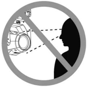 NEVER LOOK DIRECTLY INTO THE LIGHT SOURCE!RETINA INJURY RISK – MAY INDUCE BLINDNESS!SENSITIVE PERSONS MAY SUFFER AN EPILEPTIC SHOCK!
IP65 FIXTURE IS DUST TIGHT AND PROTECTED AGAINST LOW-PRESSURE WATER JETS FROM ANY DIRECTION
SAFETY GUIDELINES
– DO NOT TOUCH the fixture housing during operation. Turn OFF the power and allow approximately 15 minutes for the fixture to cool down before serving.– DO NOT shake fixture, and avoid brute force when installing and/or operating fixture.– DO NOT operate fixture if the power cord is frayed, crimped, damaged and/or if any of the power cord connectors are damaged and do not insert into the fixture easily and securely. NEVER force a power cord connector into the fixture. If the power cord or any of its connectors are damaged, replace it immediately with a new one of similar power rating.– DO NOT block any air ventilation slots.– All fan and air inlets must remain clean and never blocked.– Allow approx. 6” (15cm) between fixture and other devices or a wall for proper cooling.– When installing fixture in a suspended environment, always use mounting hardware that is no less than M10 x 25 mm, and always install fixture with an appropriately rated safety cable.– Always disconnect fixture from main power source before performing any type of service and/or cleaning procedure. Only handle the power cord by the plug end, never pull out the plug by tugging the wire portion of the cord.– During the initial operation of this fixture, a light smoke or smell may emit from the interior of the fixture. This is a normal process and is caused by excess paint in the interior of the casing burning off from the heat associated with the lamp and will decrease gradually over time.– Consistent operational breaks will ensure fixture will function properly for many years.– ONLY use the original packaging and materials to transport the fixture for service.
 CAUTION
HIGH INTENSITY ULTRAVIOLET LIGHT
AVOID DIRECT EYE & SKIN EXPOSURE.WEAR PROPER EYE & SKIN PROTECTION.SEE MANUAL FOR SAFETY INSTRUCTIONS.
RISK GROUP 3 – RISK OF EXPOSURE TO ULTRAVIOLET (UV) RADIATION!FIXTURE EMITS HIGH INTENSITY WAVELENGTH OF ULTRAVIOLET LIGHT!WEAR PROPER EYE AND SKIN PROTECTION. DO NOT OPERATE FIXTURE WITH DAMAGED/MISSING EXTERNAL COVER PROTECTIVE LENS. DO NOT LOOK DIRECTLY INTO THE (UV) LIGHT AND/OR VIEW (UV) LIGHT DIRECTLY WITH OPTICAL INSTRUMENTS THAT MAY CONCENTRATE THE LIGHT/RADIATION OUTPUT. AVOID PROLONGED PERIODS OF EXPOSURE. AVOID WEARING WHITE COLOR CLOTHING AND/OR USING (UV) PAINTS ON SKIN. AVOID DIRECT EYE AND/OR SKIN EXPOSURE AT DISTANCES OF LESS THAN 11 feet (3.3m). INDIVIDUALS SUFFERING FROM A RANGE OF EYE CONDITIONS, SUNLIGHT EXPOSURE DISORDERS, OR INDIVIDUALS USING PHOTOSENSITIVE MEDICATION MAY EXPERIENCE DISCOMFORT IF EXPOSED TO THE ULTRAVIOLET (UV) LIGHT EMITTED FROM THIS FIXTURE.
MAINTENANCE GUIDELINES
 DISCONNECT POWER BEFORE PERFORMING ANY MAINTENANCE!
CLEANINGFrequent cleaning is recommended to ensure proper function, optimized light output, and an extended life. The frequency of cleaning depends on the environment in which the fixture operates: damp, smoky, or particularly dirty environments can cause greater accumulation of dirt on the fixture’s optics. Clean the external lens surface periodically with a soft cloth to avoid dirt/debris accumulation.NEVER use alcohol, solvents, or ammonia-based cleaners.
MAINTENANCE
Regular inspections are recommended to ensure proper function and extended life. There are no user serviceable parts inside this fixture, please refer all other service issues to an authorized MAGMATIC service technician. Should you need any spare parts, please order genuine parts from your local MAGMATIC dealer.
Please refer to the following points during routine inspections:– A detailed electrical check by an approved electrical engineer every three months, to make sure the circuit contacts are in good condition in order to prevent overheating.– Be sure all screws and fasteners are securely tightened at all times. Loose screws may fall out during normal operation, resulting in damage or injury as larger parts could fall.– Check for any deformations on the housing, color lenses, rigging hardware, and rigging points (ceiling, suspension, trussing). Deformations in the housing could allow for dust or liquids to enter into the fixture. Damaged rigging points or unsecured rigging could cause the fixture to fall and seriously injure a person(s).– Electric power supply cables must not show any damage, material fatigue, or sediments.NEVER remove the ground prong from the power cable.
FIXTURE OVERVIEW
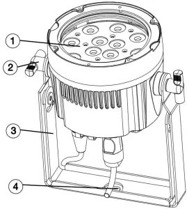

- Lens
- Yoke Adjustment Knob
- Mounting Yoke
- Clamp Attachment Point
- Safety Cable Attachment Point
- Mode Button
- Down Button
- Display Screen
- Up Button
- Enter Button
- DMX In
- Power In
- Power Out
- DMX Out
INSTALLATION INSTRUCTIONS
FLAMMABLE MATERIAL WARNINGKeep fixture minimum 5.0 feet (1.5m) away from flammable materials and/or pyrotechnics.
ELECTRICAL CONNECTIONSA qualified electrician should be used for all electrical connections and/or installations.
USE CAUTION WHEN POWER LINKING OTHER MODEL FIXTURES AS THE POWER CONSUMPTION OF OTHER MODEL FIXTURES MAYEXCEED THE MAX POWER OUTPUT ON THIS FIXTURE. CHECK SILK SCREEN FOR MAX AMPS.
DO NOT INSTALL THE FIXTURE IF YOU ARE NOT QUALIFIED TO DO SO!
THE INSTALLATION HEIGHT SHOULD BE AT LEAST 9.8 FT (3.0 METERS) ABOVE THE GROUND
Fixture MUST be installed following all local, national, and country commercial electrical and construction codes and regulations.
Before rigging/mounting a single fixture or multiple interconnected fixtures for custom matrix designs to any metal truss/structure or placing the fixture(s) on any surface, a professional equipment installer MUST be consulted to determine if the metal truss/structure or surface is properly certified to safely hold the combined weight of the fixture(s), clamps, cables, and accessories.
Ambient operating temperature range is from 14°F (-10°C) to 113°F (45°C).Do not operate this fixture when ambient temperature falls outside this range.
Fixture(s) should be installed in areas outside walking paths, seating areas, or away from areas were unauthorized personnel might reach the fixture by hand.
NEVER stand directly below the fixture(s) when rigging, removing, or servicing.Overhead fixture installation must always be secured with a secondary safety attachment, such as an appropriately rated safety cable (not included) that meets all local, national, and country codes and regulations. Allow approximately 15 minutes for the fixture to cool down before servicing.
CLAMP INSTALLATION
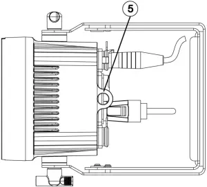
This fixture features a mounting clamp attachment point, which is located on the mounting yoke, as well as a safety cable rigging point, located on the back side of the fixture (see the illustration below). When mounting this fixture to truss, be sure to secure an appropriately rated clamp (not included) to the clamp attachment point and attach a separate SAFETY CABLE of the appropriate rating to the safety cable rigging point.
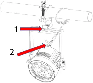
- Mounting Clamp Attachment Point
- Safety Cable Rigging Point
SAFETY CABLE
ALWAYS ATTACH A SAFETY CABLE WHENEVER INSTALLING THIS FIXTURE IN A SUSPENDED ENVIRONMENT TO ENSURE THE FIXTURE WILL NOT FALL IF THE CLAMP FAILS.
RIGGING
Overhead rigging requires extensive experience, including but not limited to: calculating working load limits, understanding the installation material being used, and periodic safety inspection of all installation material and the fixture. If you lack these qualifications, do not attempt the installation yourself. Improper installation can result in bodily injury.
The fixture includes an easy to navigate system menu. The control panel (see image below) located on the back side of the fixture provides access to the main system menu, where all necessary system adjustments can be made. During normal operation, pressing MODE button once will access the fixture’s main menu. Once in the main menu you can navigate through the different functions and access the sub-menus with the UP and DOWN buttons. Once you reach a field that requires adjusting, press the ENTER button to activate that field and use the UP and DOWN buttons to adjust the field. Pressing the ENTER button once more will confirm your setting. You may exit the main menu at any time without making any adjustments by pressing the MODE button.
The display screen will automatically time out after 30 seconds of inactivity. To unlock the display screen, simply press and hold the MODE until the display screen unlocks.

| Magmatic Prisma PAR 20 System Menu | |||
| Default setting shown in bold | |||
| Supports Software Versions: 1.01 | |||
| ADDRESS | Set ADDR XXX | 001 – 512 | |
| MODE | 1CH | ||
| 2CH | |||
| 3CH | |||
| 6CH | |||
| FUNCTION | No DMX | Hold / Black | |
| LCD Set | Display | On / Off | 30 sec. screen saver |
| Key Lock | On / On1 / Off | ||
| Flash | On / Off | ||
| Inverse | Off / On | Screen 180° flip | |
| Temp C/F | Celsius / Fahrenheit | ||
| Dim Mode | Standard | ||
| Stage | |||
| TV | |||
| Architec | |||
| Theatre | |||
| Stage2 | |||
| 0.0 s | |||
| 0.1 s | |||
| 0.2 s | |||
| 0.3 s | |||
| 0.4 s | |||
| 0.5 s | |||
| 0.6 s | |||
| 0.7 s | |||
| 0.8 s | |||
| 0.9 s | |||
| 1.0 s | |||
| 1.5 s | |||
| 2.0 s | |||
| 3.0 s | |||
| 4.0 s | |||
| 5.0 s | |||
| 6.0 s | |||
| 7.0 s | |||
| 8.0 s | |||
| 9.0 s | |||
| 10.0 s | |||
| Dim Curve | Linear | ||
| Square | |||
| Inv Square | |||
| S-Curve | |||
| Frequency | 900 Hz | ||
| 910 Hz | |||
| 920 Hz | |||
| 930 Hz | |||
| 940 Hz | |||
| 950 Hz | |||
| 960 Hz | |||
| 970 Hz | |||
| 980 Hz | |||
| 990 Hz | |||
| 1000 Hz | |||
| 1010 Hz | |||
| 1020 Hz | |||
| 1030 Hz | |||
| 1040 Hz | |||
| 1050 Hz | |||
| 1060 Hz | |||
| 1070 Hz | |||
| 1080 Hz | |||
| 1090 Hz | |||
| 1100 Hz | |||
| 1110 Hz | |||
| 1120 Hz | |||
| 1130 Hz | |||
| 1140 Hz | |||
| 1150 Hz | |||
| 1160 Hz | |||
| 1170 Hz | |||
| 1180 Hz | |||
| 1190 Hz | |||
| 1200 Hz | |||
| 1210 Hz | |||
| 1220 Hz | |||
| 1230 Hz | |||
| 1240 Hz | |||
| 1250 Hz | |||
| 1260 Hz | |||
| 1270 Hz | |||
| 1280 Hz | |||
| 1290 Hz | |||
| 1300 Hz | |||
| 1310 Hz | |||
| 1320 Hz | |||
| 1330 Hz | |||
| 1340 Hz | |||
| 1350 Hz | |||
| 1360 Hz | |||
| 1370 Hz | |||
| 1380 Hz | |||
| 1390 Hz | |||
| 1400 Hz | |||
| 1410 Hz | |||
| 1420 Hz | |||
| 1430 Hz | |||
| 1440 Hz | |||
| 1450 Hz | |||
| 1460 Hz | |||
| 1470 Hz | |||
| 1480 Hz | |||
| 1490 Hz | |||
| 1500 Hz | |||
| 2500 Hz | |||
| 4000 Hz | |||
| 5000 Hz | |||
| 6000 Hz | |||
| 10 KHz | |||
| 15 KHz | |||
| 20 KHz | |||
| 25 KHz | |||
| MasterSwitch | On / Off | ||
| Defaults | Reset? | ||
| Cancel | |||
| INFORMATION | Time Info | Current | |
| Total | |||
| Last | |||
| Password | Clear Current/Last (Password = 050) | ||
| Clear Total (Password = 060) | |||
| Clear | On / Off | ||
| Temp Info | |||
| Model Info | Prisma Par 20 | ||
| Software | V1.01 | ||
| Err. Info | None | ||
| SLAVE | Press ENTER to put fixture in Slave Mode.
Slave Mode will automatically be deactivated when the fixture is set to another operational mode. |
||
| MANUAL | Dimmer | 000 – 255 | |
| Strobe | 000 – 255 | ||
| UV | 000 – 255 | ||
| CALIBRATION | Password | Password = 050 | |
| UV |
DMX CHANNEL FUNCTIONS AND VALUES
1-CH MODE
| Magmatic Prisma PAR 20: DMX Channels / Functions (1 DMX Channel) | ||
| Supports Software Versions: 1.01 | ||
| CHANNEL | VALUE | FUNCTION |
| 1 | 000 – 255 | Dimmer |
2-CH MODE
| Magmatic Prisma PAR 20: DMX Channels / Functions (2 DMX Channels) | ||
| Supports Software Versions: 1.01 | ||
| CHANNEL | VALUE | FUNCTION |
| 1 | 000 – 255 | Dimmer |
| 2 | 000 – 255 | Dimmer Fine |
3-CH MODE
| Magmatic Prisma PAR 20: DMX Channels / Functions (3 DMX Channels) | ||
| Supports Software Versions: 1.01 | ||
| CHANNEL | VALUE | FUNCTION |
| 1 | Strobe | |
| 000 – 031 | LED Off | |
| 032 – 063 | LED On | |
| 064 – 095 | Strobe, slow to fast | |
| 096 – 127 | LED On | |
| 128 – 159 | Pulse effect in sequences | |
| 160 – 191 | LED On | |
| 192 – 223 | Random strobe effect, slow to fast | |
| 224 – 255 | LED On | |
| 2 | 000 – 255 | Dimmer |
| 3 | 000 – 255 | Dimmer Fine |
6-CH MODE
| Magmatic Prisma PAR 20: DMX Channels / Functions (6 DMX Channels) | ||
| Supports Software Versions: 1.01 | ||
| CHANNEL | VALUE | FUNCTION |
| 1 | Strobe | |
| 000 – 031 | LED Off | |
| 032 – 063 | LED On | |
| 064 – 095 | Strobe, slow to fast | |
| 096 – 127 | LED On | |
| 128 – 159 | Pulse effect in sequences | |
| 160 – 191 | LED On | |
| 192 – 223 | Random strobe effect, slow to fast | |
| 224 – 255 | LED On | |
| 2 | 000 – 255 | Dimmer |
| 3 | 000 – 255 | Dimmer Fine |
| 4 | Dim Mode | |
| 000 – 020 | Standard | |
| 021 – 040 | Stage | |
| 041 – 060 | TV | |
| 061 – 080 | Architectural | |
| 081 – 100 | Theatre | |
| 101 – 120 | Stage2 | |
| Dimmer Delay Time | ||
| 121 | 0.0 s | |
| 122 | 0.1 s | |
| 123 | 0.2 s | |
| 124 | 0.3 s | |
| 125 | 0.4 s | |
| 126 | 0.5 s | |
| 127 | 0.6 s | |
| 128 | 0.7 s | |
| 129 | 0.8 s | |
| 130 | 0.9 s | |
| 131 | 1.0 s | |
| 132 | 1.5 s | |
| 133 | 2.0 s | |
| 134 | 3.0 s | |
| 135 | 4.0 s | |
| 136 | 5.0 s | |
| 137 | 6.0 s | |
| 138 | 7.0 s | |
| 139 | 8.0 s | |
| 140 | 9.0 s | |
| 141 | 10.0 s | |
| 142 – 255 | No Function | |
| 5 | Dim Curves | |
| 000 – 020 | Linear | |
| 021 – 040 | Square | |
| 041 – 060 | Inv. Squa. | |
| 061 – 080 | S. Curve | |
| 081 – 255 | No Function | |
| 6 | LED Refresh Rates | |
| 000 – 010 | 1200 Hz (Default Refresh Rate) | |
| 011 | 900 Hz | |
| 012 | 910 Hz | |
| 013 | 920 Hz | |
| 014 | 930 Hz | |
| 015 | 940 Hz | |
| 016 | 950 Hz | |
| 017 | 960 Hz | |
| 018 | 970 Hz | |
| 019 | 980 Hz | |
| 020 | 990 Hz | |
| 021 | 1000 Hz | |
| 022 | 1010 Hz | |
| 023 | 1020 Hz | |
| 024 | 1030 Hz | |
| 025 | 1040 Hz | |
| 026 | 1050 Hz | |
| 027 | 1060 Hz | |
| 028 | 1070 Hz | |
| 029 | 1080 Hz | |
| 030 | 1090 Hz | |
| 031 | 1100 Hz | |
| 032 | 1110 Hz | |
| 033 | 1120 Hz | |
| 034 | 1130 Hz | |
| 035 | 1140 Hz | |
| 036 | 1150 Hz | |
| 037 | 1160 Hz | |
| 038 | 1170 Hz | |
| 039 | 1180 Hz | |
| 040 | 1190 Hz | |
| 041 | 1210 Hz | |
| 042 | 1220 Hz | |
| 043 | 1230 Hz | |
| 044 | 1240 Hz | |
| 045 | 1250 Hz | |
| 046 | 1260 Hz | |
| 047 | 1270 Hz | |
| 048 | 1280 Hz | |
| 049 | 1290 Hz | |
| 050 | 1300 Hz | |
| 051 | 1310 Hz | |
| 052 | 1320 Hz | |
| 053 | 1330 Hz | |
| 054 | 1340 Hz | |
| 055 | 1350 Hz | |
| 056 | 1360 Hz | |
| 057 | 1370 Hz | |
| 058 | 1380 Hz | |
| 059 | 1390 Hz | |
| 060 | 1400 Hz | |
| 061 | 1410 Hz | |
| 062 | 1420 Hz | |
| 063 | 1430 Hz | |
| 064 | 1440 Hz | |
| 065 | 1450 Hz | |
| 066 | 1460 Hz | |
| 067 | 1470 Hz | |
| 068 | 1480 Hz | |
| 069 | 1490 Hz | |
| 070 | 1500 Hz | |
| 071 | 2500 Hz | |
| 072 | 4000 Hz | |
| 073 | 5000 Hz | |
| 074 | 6000 Hz | |
| 075 | 10 KHz | |
| 076 | 15 KHz | |
| 077 | 20 KHz | |
| 078 | 25 KHz | |
| 079 – 255 | No Function |
DIMMER MODES
Select desired DIMMER MODE (Standard, Stage, TV, Architectural, Theatre, Stage2).
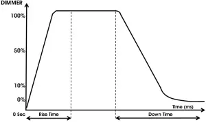
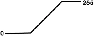
| Dimming Curve Ramp Effect
|
0 sec Fade Time | 1 sec Fade Time | ||
 |
 |
|||
| Rise Time (ms) | Down Time (ms) | Rise Time (ms) | Down Time (ms) | |
| Standard (default) | 0 | 0 | 0 | 0 |
| Stage | 780 | 1100 | 1540 | 1660 |
| TV | 1180 | 1520 | 1860 | 1940 |
| Architectural | 1380 | 1730 | 2040 | 2120 |
| Theatre | 1580 | 1940 | 2230 | 2280 |
| Stage 2 | 0 | 1100 | 0 | 1660 |
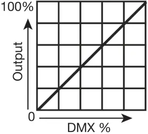
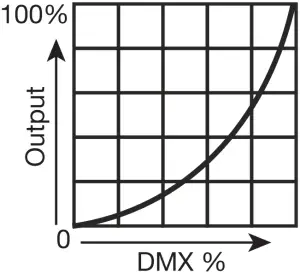
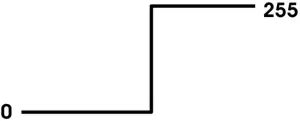
LINEAR SQUARE
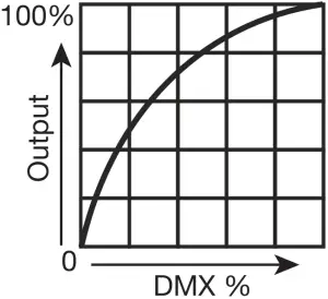
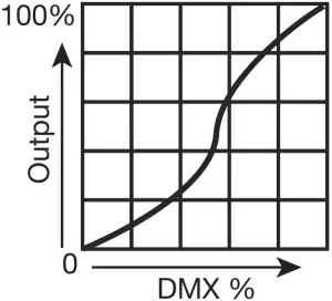
INVERSE SQUARE S-CURVE
SPECIFICATIONS
SOURCE(12) 2W High Power UV Diode LEDs20,000 Hour Average LED Life*
*Test lab conditions. May vary depending on several factors including but not limited to:Environmental Conditions, Power/Voltage, Usage Patterns (On-Off Cycling), Control, and Dimming.
PHOTOMETRIC DATA20 Degree Narrow Beam Angle365nm True UV Peak Wavelength
EFFECTSHigh Speed Electronic StrobeVariable Dimming Curve Modes
CONSTRUCTIONRugged IP65 Rated HousingDual Adjustable Mounting Yokes
CONTROLMultiple DMX Channel ModesOnboard 4 Button Touch Control PanelDMX-512 and RDM Protocol Support
CONNECTIONSLocking 5pin XLR Connector In/OutIP65 Locking Power Connector In
SIZE / WEIGHTLength: 5.9 in. (150mm)Width: 8.6 in. (218mm)Vertical Height: 9.7 in. (247mm)Weight: 5.3 lbs. (2.4kg)
ELECTRICALAC100-240V 50-60Hz27W Max Power Consumption
THERMAL14°F to 113°F (-10°C to 45°C)Air Cooled

APPROVALS / RATINGSCE | cETLus | IP65
Specifications and improvements in the design of this unit and this manual are subject to change without any prior written notice.
DIMENSIONAL DRAWINGS
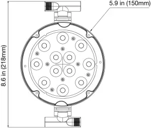
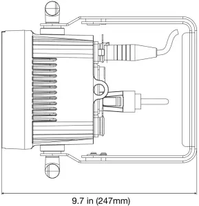
Drawings not to scale.
FCC STATEMENT
This device complies with Part 15 of the FCC Rules. Operation is subject to the following two conditions: (1) this device may not cause harmful interference, and (2) this device must accept any interference received, including interference that may cause undesired operation.
FCC RADIO FREQUENCY INTERFERENCE WARNINGS & INSTRUCTIONS
This product has been tested and found to comply with the limits as per Part 15 of the FCC Rules. These limits are designed to provide reasonable protection against harmful interference in a residential installation. This device uses and can radiate radio frequency energy and, if not installed and used in accordance with the included instructions, may cause harmful interference to radio communications. However, there is no guarantee that interference will not occur in a particular installation. If this device does cause harmful interference to radio or television reception, which can be determined by turning the device off and on, the user is encouraged to try to correct the interference by one or more of the following methods:
- Reorient or relocate the device.
- Increase the separation between the device and the receiver.
- Connect the device to an electrical outlet on a circuit different from which the radio receiver is connected.
- Consult the dealer or an experienced radio/TV technician for help.

 report this ad
SKU#: PSP020EU#: 1237000232UPC#: 810008261149ITF-14#: 10810008261146
References
[xyz-ips snippet=”download-snippet”]